
Related Manuals for DFI CM901-B


Summary of Contents for DFI CM901-B
- Page 1 CM901-B COM Express Basic Module User’s Manual A22410343 Chapter 1 Introduction www.dfi.com...
-
Page 2: Copyright
Product names or trademarks appearing in this manual are for identification purpose only and 2. Shielded interface cables must be used in order to comply with the emission limits. are the properties of the respective owners. COM Express Specification Reference PICMG COM Express Module Base Specification. ® http://www.picmg.org/ Chapter 1 Introduction www.dfi.com... -
Page 3: Table Of Contents
....................15 CPU Fan Connector ..................15 COM Express Connectors ................16 COM Express connector Signal Discription ............ 17 Standby Power LED ................... 29 Cooling Option .................... 29 Installing CM901-B onto a Carrier Board ..........30 Chapter 1 Introduction www.dfi .com... -
Page 4: About This Manual
ESD protection. Safety Measures To avoid damage to the system: • Use the correct AC input voltage range. To reduce the risk of electric shock: • Unplug the power cord before removing the system chassis cover for installation or servic- ing. After installation or servicing, cover the system chassis before plugging the power cord. Chapter 1 Introduction www.dfi.com... -
Page 5: About The Package
About the Package The package contains the following items. If any of these items are missing or damaged, please contact your dealer or sales representative for assistance. • One CM901-B board • One DVD • One QR (Quick Reference) Optional Items •... -
Page 6: Chapter 1 - Introduction
Chapter 1 Chapter 1 - Introduction Watchdog • Watchdog timeout programmable via software from 1 to 255 seconds Specifications Timer SSD (optional) • 4GB/8GB/16GB/32GB • Write: 30MB/sec (max), Read: 70MB/sec (max) ® Processor • AMD Embedded R-Series APUs • SATA to SSD onboard : R-464L Quad-core 2.3GHz, 35W : R-460H Quad-core 1.9GHz, 35W Trusted... -
Page 7: Features
Chapter 1 Features • Watchdog Timer The Watchdog Timer function allows your application to regularly “clear” the system at the set time interval. If the system hangs or fails to function, it will reset at the set time interval so that your system will continue to operate. -
Page 8: Chapter 2 - Concept
Chapter 2 - Concept COM Express Module Standards The figure below shows the dimensions of the different types of COM Express modules. CM901-B is a COM Express Basic module. The dimension is 95mm x 125mm. Common for all Form Factors Extended only... -
Page 9: Specification Comparison Table
Chapter 2 Specification Comparison Table The table below shows the COM Express standard specifications and the corresponding specifications supported on the CM901-B module. COM Express Module Base DFI CM901-B COM Express Module Base DFI CM901-B Specification Type 6 Type 6... -
Page 10: Chapter 3 - Hardware Installation
Chapter 3 Chapter 3 - Hardware Installation Block Diagram Board Layout LVDS (Dual Channel) DDI Port 2 (SW1) DP to LVDS TRANSLATOR Processor CH7511B CORE CORE CORE CORE 800~1600MT/s UNBUFFERED DDR3 SODIMM 2x DISPLAY Port AMD Embedded SWITCH PCIe GEN2 x16 PCIe GEN2 x16 R-Series APUs PI3VDP12412... -
Page 11: Mechanical Diagram
Chapter 3 Bottom View 14.00 Mechanical Diagram 2.00 CM901-B Module 0.00 CM901-B Module with Heat Sink 91.00 91.00 87.00 87.00 95.00 4.00 34.20 87.00 Top View 45.34 0.00 0.00 4.00 4.00 125.00 Ø2.70(*7 pcs) 4.00 76.00 4.00 83.00 Heat sink with fan... -
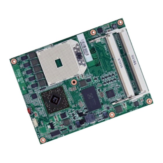
Page 12: System Memory
When the Standby Power LED lit red, it indicates that there is power on the system board. Power-off the PC then unplug the power cord prior to installing any devices. Failure to do so will cause severe damage to the motherboard and components. DDR3_2 DDR3_1 Standby Power LED Chapter 3 Hardware Installation www.dfi.com... -
Page 13: Installing The Dimm Module
6. Push down the module until the clips at each end of the socket lock into position. You will hear a distinctive “click”, indicating the module is correctly locked into position. Clip Clip Chapter 3 Hardware Installation www.dfi.com... -
Page 14: Cpu
Do not force the CPU into the socket. Forcing the CPU into the socket may bend the its unlock position. Screw in unlocked pins and damage the CPU. position Chapter 3 Hardware Installation www.dfi.com... -
Page 15: Connectors
Chapter 3 Connectors COM Express Connectors The COM Express connectors are used to interface the CM901-B COM Express board to a car- CPU Fan Connector rier board. Connect the COM Express connectors (lcoated on the solder side of the board) to the COM Express connectors on the carrier board. -
Page 16: Com Express Connectors
VCC_12V PEG_RX0- PEG_TX0- C108 VCC_12V D108 VCC_12V GPI0 GPO1 A109 VCC_12V B109 VCC_12V TYPE0# PEG_LANE_RV# C109 VCC_12V D109 VCC_12V PCIE_TX4+ PCIE_RX4+ A110 GND (FIXED) B110 GND (FIXED) PEG_RX1+ PEG_TX1+ C110 GND (FIXED) D110 GND (FIXED) Chapter 3 Hardware Installation www.dfi.com... -
Page 17: Com Express Connector Signal Discription
AC coupled on Module Serial ATA or SAS Channel 1 transmit differential pair. SATA1_TX- O SATA AC coupled on Module Chapter 3 Hardware Installation www.dfi.com SATA1_RX+ I SATA AC coupled on Module Serial ATA or SAS Channel 1 receive differential pair. - Page 18 PCI Express Differential Transmit Pairs 5 PCIE_TX5- PCIE_RX5+ I PCIE AC coupled off Module PCI Express Differential Receive Pairs 5 PCIE_RX5- PCIE_TX6+ O PCIE AC coupled on Module PCI Express Differential Transmit Pairs 6 Chapter 3 Hardware Installation www.dfi.com PCIE_TX6-...
- Page 19 PCI Express Graphics transmit differential pairs 1 PEG_TX1- PEG_RX1+ I PCIE AC coupled off Module PCI Express Graphics receive differential pairs 1 PEG_RX1- PEG_TX2+ O PCIE AC coupled on Module PCI Express Graphics transmit differential pairs 2 Chapter 3 Hardware Installation www.dfi.com PEG_TX2-...
- Page 20 PCI Express Graphics receive differential pairs 10 PEG_RX10- PEG_TX11+ O PCIE AC coupled on Module PCI Express Graphics transmit differential pairs 11 PEG_TX11- Chapter 3 Hardware Installation www.dfi.com PEG_RX11+ I PCIE AC coupled off Module PCI Express Graphics receive differential pairs 11...
- Page 21 AC coupled on Module PCI Express Graphics transmit differential pairs 11 PEG_TX11- USB5+ I/O USB 3.3V Suspend/3.3V USB differential pairs 5 Chapter 3 Hardware Installation www.dfi.com USB5- PEG_RX11+ I PCIE AC coupled off Module PCI Express Graphics receive differential pairs 11...
- Page 22 Chapter 3 DDI Signals Descriptions Signal Pin# Pin Type Pwr Rail /Tolerance PU/PD Description DDI1_PAIR0+/SDVO1_RED+ O PCIE AC coupled off Module DDI 1 Pair 0 differential pairs/Serial Digital Video B red output differential pair DDI1_PAIR0-/SDVO1_RED- DDI1_PAIR1+/SDVO1_GRN+ O PCIE AC coupled off Module DDI 1 Pair 1 differential pairs/Serial Digital Video B green output differential pair DDI1_PAIR1-/SDVO1_GRN- DDI1_PAIR2+/SDVO1_BLU+...
- Page 23 AC coupled off Modul Additional receive signal differential pairs for the SuperSpeed USB data path. USB_SSRX2- USB_SSTX3+ O PCIE AC coupled on Module Additional transmit signal differential pairs for the SuperSpeed USB data path. Chapter 3 Hardware Installation www.dfi.com USB_SSTX3-...
- Page 24 PU 10K to 3.3V LPC serial interrupt USB_SSTX3+ O PCIE AC coupled on Module Additional transmit signal differential pairs for the SuperSpeed USB data path. Chapter 3 Hardware Installation USB_SSTX3- www.dfi.com LPC_CLK O CMOS 3.3V / 3.3V LPC clock output - 33MHz nominal...
- Page 25 O CMOS 5V / 12V General purpose serial port 1 transmitter SER1_RX A102 I CMOS 5V / 12V General purpose serial port 1 receiver Miscellaneous Signal Descriptions Chapter 3 Hardware Installation www.dfi.com Signal Pin# Pin Type Pwr Rail /Tolerance PU/PD Description...
- Page 26 PWR_OK input, a VCC_12V power input that falls below the minimum specification, a watchdog timeout, or may be initiated by the Module software. Chapter 3 Hardware Installation www.dfi.com PWR_OK I CMOS 3.3V / 3.3V Power OK from main power supply. A high value indicates that the...
- Page 27 Chapter 3 Power and System Management Signals Descriptions Signal Pin# Pin Type Pwr Rail /Tolerance PU/PD Description PWRBTN# I CMOS 3.3V Suspend/3.3V PU 10K to 3.3VSB A falling edge creates a power button event. Power button events can be used to bring a system out of S5 soft off and other suspend states, as well as powering the system down.
- Page 28 B90, B100, B110, C1, C2, C5, C8, C11, C14, C21, C31, C41, C51, C60, C70, C73, C76, C80, C84, C87, C90, C93, C96, C100, C103, C110, D1, D2, D5, D8, D11, D14, D21, D31, D51, D60, Chapter 3 Hardware Installation www.dfi.com...
-
Page 29: Standby Power Led
Bottom View of the Heat Sink • “1”, “2” and “3” denote the locations of the thermal pads designed to contact the corresponding components that are on CM901-B. Important: Remove the plastic covering from the thermal pads prior to mounting the heat sink onto CM901-B. -
Page 30: Installing Cm901-B Onto A Carrier Board
The carrier board (COM331-B) used in this section is for reference purpose only and may not resemble your carrier board. These illustrations are mainly to guide you on how to install CM901-B onto the carrier board of your choice. Mounting hole •... - Page 31 Bolts Bolts 7. Position the heat sink on top of CM901-B with the heat sink’s mounting holes aligned with CM901-B’s mounting holes. Insert one of the provided long screws into the mounting hole 5. The photo below shows the solder side of the board with the screws already fixed in place.
- Page 32 The photo below shows the locations of the long/short mounting screws. 9. Grasping CM901-B by its edges, position it on top of the carrier board with its mounting holes aligned with the bolts on the carrier board. This will also align the COM Express connectors of the two boards to each other.
-
Page 33: Chapter 4 - Bios Setup
Chapter 4 Chapter 4 - BIOS Setup Legends Overview KEYs Function The BIOS is a program that takes care of the basic level of communication between the CPU and peripherals. It contains codes for various advanced features found in this system board. Right and Left Arrows Moves the highlight left or right to select a The BIOS allows you to configure the system and save the configuration in a battery-backed... -
Page 34: Ami Bios Setup Utility
Total Memory 2032 MB (DDR3) ACPI Settings System ACPI Parameters. Trusted Computing System Language [English] DFI Wakeup Confi guration PC Health Status System Date [Sun 01/02/2011] CPU Confi guration System Time [14:22:36] ... - Page 35 Chapter 4 ACPI Settings Trusted Computing This section is used to configure the ACPI settings. This section configures settings relevant to Trusted Computing innovations. Aptio Setup Utility - Copyright (C) 2011 American Megatrends, Inc. Aptio Setup Utility - Copyright (C) 2011 American Megatrends, Inc. Advanced Advanced ACPI Settings...
- Page 36 Aptio Setup Utility - Copyright (C) 2011 American Megatrends, Inc. Aptio Setup Utility - Copyright (C) 2011 American Megatrends, Inc. Advanced Advanced DFI Wakeup ACPI Power Management Confi guration About resume by PME System Hardware Monitor (PCI, PCIE, LAN). CPU Temperature...
- Page 37 Chapter 4 CPU Configuration Node 0 Information This section is used to configure the CPU. It will also display the detected CPU information. Aptio Setup Utility - Copyright (C) 2011 American Megatrends, Inc. Advanced Socket 0: AMD R-464L APU with Radeon(tm) HD Graphics Aptio Setup Utility - Copyright (C) 2011 American Megatrends, Inc.
- Page 38 Chapter 4 DDR3 Voltage Setting IDE Configuration This section is used to configure the DDR3 Voltage Setting. This section is used to configure IDE functions. Aptio Setup Utility - Copyright (C) 2011 American Megatrends, Inc. Aptio Setup Utility - Copyright (C) 2011 American Megatrends, Inc. Advanced Advanced IDE Confi...
- Page 39 Chapter 4 USB Configuration Onboard VGA Setting This section is used to configure USB. This section displays the onboard VGA setting. Aptio Setup Utility - Copyright (C) 2011 American Megatrends, Inc. Aptio Setup Utility - Copyright (C) 2011 American Megatrends, Inc. Advanced Advanced Display Port3 TO VGA Mode...
- Page 40 Chapter 4 Network Stack UEFI PXE This section displays the UEFI PXE. This section configures settings relevant to the network stack. Aptio Setup Utility - Copyright (C) 2011 American Megatrends, Inc. Aptio Setup Utility - Copyright (C) 2011 American Megatrends, Inc. Advanced Advanced UEFI PXE Driver...
- Page 41 Version 2.14.1219. Copyright (C) 2011 American Megatrends, Inc. WatchDog function This field is used to enable or disable the Watchdog timer function. Watchdog 1 function For CM901-B module board (Reset CM901-B by hardware) Watchdog 2 function For carrier board usage. Chapter 4 BIOS Setup...
-
Page 42: Chipset
Chapter 4 Chipset South Bridge This section configures relevant chipset functions. Aptio Setup Utility - Copyright (C) 2011 American Megatrends, Inc. Chipset AMD Reference Code Version: Trinity PI 1.0.0.1 Options for SATA Conigu- Aptio Setup Utility - Copyright (C) 2011 American Megatrends, Inc. ration. - Page 43 Chapter 4 SB SATA Configuration SB USB Configuration Aptio Setup Utility - Copyright (C) 2011 American Megatrends, Inc. Aptio Setup Utility - Copyright (C) 2011 American Megatrends, Inc. Chipset Chipset OnChip SATA Channel [Enabled] XHCI Controller 0 [Enabled] XHCI ENABLE help. OnChip SATA Type [Native IDE] XHCI Controller 1...
- Page 44 Chapter 4 North Bridge Configuration GFX Configuration Aptio Setup Utility - Copyright (C) 2011 American Megatrends, Inc. Aptio Setup Utility - Copyright (C) 2011 American Megatrends, Inc. Chipset Chipset North Bridge Confi guration GFX Confi guration. GFX Confi guration Select Primary Video Device that BIOS will use ...
- Page 45 Chapter 4 Memory Configuration Socket 0 Information Aptio Setup Utility - Copyright (C) 2011 American Megatrends, Inc. Aptio Setup Utility - Copyright (C) 2011 American Megatrends, Inc. Chipset Chipset Memory Confi guration Memory Hole Remapping Socket 0 Information Memory Hole Remapping [Enabled] Starting Address: 0 KB Ending Address: 2097151 KB...
-
Page 46: Boot
Chapter 4 Boot CSM Parameters Aptio Setup Utility - Copyright (C) 2011 American Megatrends, Inc. Aptio Setup Utility - Copyright (C) 2011 American Megatrends, Inc. Main Advanced Main Advanced Chipset Boot Security Save & Exit Chipset Boot Security Save & Exit Launch CSM [Always] This option controls if... -
Page 47: Security
Chapter 4 Security Save & Exit Aptio Setup Utility - Copyright (C) 2011 American Megatrends, Inc. Aptio Setup Utility - Copyright (C) 2011 American Megatrends, Inc. Main Advanced Chipset Boot Security Save & Exit Main Advanced Chipset Boot Security Save & Exit Save Changes and Reset Reset the system after Password Description... -
Page 48: Updating The Bios
Chapter 4 Updating the BIOS Save as User Defaults To save changes done so far as user default, select this field and then press <Enter>. To update the BIOS, you will need the new BIOS file and a flash utility, AFUDOS.EXE. A dialog box will appear. -
Page 49: Chapter 5 - Supported Software
Chapter 5 Chapter 5 - Supported Software AMD Embedded GPU and Chipset Software Installation The CD that came with the system board contains drivers, utilities and software applications Utility required to enhance the performance of the system board. Insert the CD into a CD-ROM drive. The autorun screen (Mainboard Utility CD) will appear. If To install the driver, click “AMD Embedded GPU and Chipset Software Installation Utility”... - Page 50 Chapter 5 Intel LAN Driver 3. Click Express and then click Next. To install the driver, click “Intel LAN Drivers” on the main menu. 1. Setup is ready to install the driver. Click Install Drivers and Sofeware. 2. Setup is now ready to install the LAN driver.
- Page 51 Chapter 5 Realtek Audio Driver (optional) 4. Select the program featuers you want installed then click Next. To install the driver, click “Realtek Audio Driver” on the main menu 1. Setup is now ready to install the audio driver. Click Next. 2.
- Page 52 Chapter 5 AMD RAIDXpert 4. Click Next to install or click Browse to select another folder. To install the driver, click “AMD RAIDXpert” on the main menu. 1. Under the Language Sup- port section, select the language you would like the installation to display and then click OK.
- Page 53 Chapter 5 F6 Floppy 7. Click Finish to exit installation. This is used to create a floppy driver diskette needed when you install Windows® XP using the F6 installation method. This will allow you to install the operating system onto a hard drive when in AHCI mode.
- Page 54 Chapter 5 TPM Driver and Tools (optional) 4. Enter the necessary information and then click Next. To install the driver, click “Infineon TPM driver and tool (option)” on the main menu. 1. Read the message and click OK. 5. Select a setup type and then click Next.
- Page 55 Chapter 5 Microsoft .NET Framework 4 (Optional) 7. The setup program is currently installing the software. To install the driver, click “Microsoft .NET Framework 4” on the main menu. 1. Click “I have read and accept the license terms” and then click Install.
- Page 56 Chapter 5 DFI Utility 3. Click Finish. DFI Utility provides information about the board, HW Health, Watchdog, DIO, and Backlight. To access the utility, click “DFI Utility” on the main menu. Note: If you are using Windows 7, you need to access the operating system as an administrator to be able to install the utility.
- Page 57 Chapter 5 The DFI Utility icon will appear on the desktop. Double-click the icon to open the utility. 3. Enter “User Name” and “Organi- zation” information and then click Next 4. Click Install to begin the installation. 5. After completing installation, click Finish.
- Page 58 Chapter 5 Adobe Acrobat Reader 9.3 To install the reader, click “Adobe Acrobat Reader 9.3” on the main menu. 1. Click Next to install or click Change Destination Folder to select another folder. 2. Click Install to begin installation. 3. Click Finish to exit installation. Chapter 5 Supported Software www.dfi...
-
Page 59: Appendix A - Nlite And Ahci Installation Guide
Appendix A Appendix A - NLITE and AHCI Installation Guide 4. Insert the XP installation disc into an optical drive. nLite 5. Launch nLite. The Welcome screen will appear. Click nLite is an application program that allows you to customize your XP installation disc by Next. - Page 60 Appendix A 7. Click Next. 9. Click Insert and then select Multiple driver folder to select the drivers you will integrate. Click Next. 8. In the Task Selection dialog 10. Select only the drivers ap- box, click Drivers and propriate for the Windows Bootable ISO.
- Page 61 Appendix A 11. If you are uncertain of the 13. The program is currently southbridge chip used on integrating the drivers and your motherboard, select all applying changes to the RAID/AHCI controllers and installation. then click OK 14. When the program is fin- ished applying the changes, click Next.
- Page 62 Appendix A 15. To create an image, select the 17. You have finished customizing Create Image mode under the the Windows XP installation disc. General section and then click Click Finish. Next. Enter the BIOS utility to configure the SATA controller to RAID/AHCI. You can now install Windows XP.
-
Page 63: Ahci
Appendix A AHCI 5. In the Hardware Update Wizard dialog box, select “No, not this time” then click Next. The installation steps below will guide you in configuring your SATA drive to AHCI mode. 1. Enter the BIOS utility and configure the SATA controller to IDE mode. 2. - Page 64 Appendix A 8. Click “Have Disk”. 11. A warning message appeared because the selected SATA controller did not match your hardware device. Ignore the warning and click Yes to proceed. 12. Click Finish. 9. Select C:\AHCI\iaAHCI.inf and then click Open. 13.
-
Page 65: Appendix B - Watchdog Sample Code
Appendix B Appendix B - Watchdog Sample Code #include <stdio.h> int GetWDTime(void) //-------------------------------------------------------------- #defi ne EC_EnablePort 0x66 int sum,data_h,data_l; #defi ne EC_DataPort 0x62 //Select EC Read Type //-------------------------------------------------------------- outportb(EC_EnablePort,0x80); void WriteEC(char,int); delay(5); void SetWDTime(int,int); //Get Remaining Count High Byte int GetWDTime(void); outportb(EC_DataPort,0xF6);... -
Page 66: Appendix C - System Error Message
Appendix C Appendix C - System Error Message When the BIOS encounters an error that requires the user to correct something, either a beep code will sound or a message will be displayed in a box in the middle of the screen and the message, PRESS F1 TO CONTINUE, CTRL-ALT-ESC or DEL TO ENTER SETUP, will be shown in the information box at the bottom. -
Page 67: Appendix D - Troubleshooting
Appendix D Appendix D - Troubleshooting The picture seems to be constantly moving. 1. The monitor has lost its vertical sync. Adjust the monitor’s vertical sync. Troubleshooting Checklist 2. Move away any objects, such as another monitor or fan, that may be creating a magnetic This chapter of the manual is designed to help you with problems that you may encounter field around the display. -
Page 68: Hard Drive
Appendix D Hard Drive System Board 1. Make sure the add-in card is seated securely in the expansion slot. If the add-in card is Hard disk failure. loose, power off the system, re-install the card and power up the system. 1. -
Page 69: Appendix E - Bios Status Code
Appendix E Appendix E - BIOS Status Code PEI Status Codes Status Code Ranges Standard Status Codes SEC Status Codes Appendix E BIOS Status Code www.dfi .com... - Page 70 Appendix E PEI Beep Codes DXE Status Codes Appendix E BIOS Status Code www.dfi .com...
- Page 71 Appendix E Appendix E BIOS Status Code www.dfi .com...
- Page 72 Appendix E OEM-Reserved Status Code Ranges DXE Beep Codes ACPI/ASL Status Codes Appendix E BIOS Status Code www.dfi .com...
Need help?
Do you have a question about the CM901-B and is the answer not in the manual?
Questions and answers