
Related Manuals for DFI CR960-QM77


Summary of Contents for DFI CR960-QM77
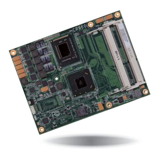
- Page 1 CR960-QM77/HM76 COM Express Basic User’s Manual A27110442 Chapter 1 Introduction www.dfi .com...
-
Page 2: Copyright
Copyright FCC and DOC Statement on Class B This publication contains information that is protected by copyright. No part of it may be re- This equipment has been tested and found to comply with the limits for a Class B digital produced in any form or by any means or used to make any transformation/adaptation without device, pursuant to Part 15 of the FCC rules. -
Page 3: Table Of Contents
....................13 CPU Fan Connector..................13 COM Express Connectors ................14 COM Express Connectors Signal Discription ..........17 Standby Power LED ................... 27 Cooling Option .................... 27 Installing CR960-QM77/HM76 onto a Carrier Board ......28 Chapter 1 Introduction www.dfi .com... -
Page 4: About This Manual
About this Manual Static Electricity Precautions An electronic file of this manual is included in the CD. To view the user’s manual in the CD, It is quite easy to inadvertently damage your PC, system board, components or devices even insert the CD into a CD-ROM drive. -
Page 5: About The Package
About the Package The package contains the following items. If any of these items are missing or damaged, please contact your dealer or sales representative for assistance. • One CR960 board • One DVD • One QR (Quick Reference) Optional Items •... -
Page 6: Chapter 1 - Introduction
2 SATA 2.0 with data transfer rate up to 3Gb/s Power • Input: 5VSB (optional), 12V, VCC_RTC • Integrated Advanced Host Controller Interface (AHCI) controller • Supports RAID 0/1/5/10 (CR960-QM77 only) • Dimensions - 95mm (3.74") x 125mm (4.9") ®... -
Page 7: Features
Chapter 1 Features • Watchdog Timer The Watchdog Timer function allows your application to regularly “clear” the system at the set time interval. If the system hangs or fails to function, it will reset at the set time interval so that your system will continue to operate. -
Page 8: Chapter 2 - Concept
Chapter 2 - Concept COM Express Module Standards The figure below indicates the dimensions of the different types of COM Express modules. CR960-QM77/HM76 is a COM Express Basic. The dimension is 95mm x 125mm. Common for all Form Factors Extended only... -
Page 9: Specification Comparison Table
Chapter 2 Specification Comparison Table The table below shows the COM Express standard specifications and the corresponding specifications supported on the CR960-QM77/HM76 module. COM Express Module Base COM Express Module Base Specification Type 6 CR960-QM77/HM76 Specification Type 6 CR960-QM77/HM76 Connector... -
Page 10: Chapter 3 - Hardware Installation
CPU fan (Direct Media Interface) LPC Bus CPU Fan QM77/HM76 SLP/LID SLP/LID LPC TPM (optional) CR960-QM77: QM77 DDI Port B/SDVO Port B DDI Port B/SDVO Port B 1.2 (Opt.) CR960-HM76: HM76 Serial Port 0/1 System Fan Embedded Standby PWM/TACH_IN Power LED... -
Page 11: Mechanical Diagram
Chapter 3 Bottom View Mechanical Diagram 14.00 2.00 CR960-QM77/HM76 Module with Heat Sink CR960-QM77/HM76 Module 0.00 53.00 4.00 4.00 0.00 87.00 0.00 95.00 Top View 87.00 87.00 91.00 91.00 Heatsink 125.00 Heat spreader Module PCB Standoff Side View of the Module with Heat Sink and Carrier Board Bottom View 14.00... -
Page 12: System Memory
When the Standby Power LED lit red, it indicates that there is power on the board. Power-off the PC then unplug the power cord prior to installing any devices. Failure to do so will cause severe damage to the board and components. DDR3_2 DDR3_1 Standby Power LED Chapter 3 Hardware Installation www.dfi.com... -
Page 13: Connectors
BIOS Setting “Module Board H/W Monitor” submenu in the Advanced menu of the BIOS will display the cur- Clip Clip rent speed of the cooling fan. Refer to chapter 4 of the manual for more information Chapter 3 Hardware Installation www.dfi.com... -
Page 14: Com Express Connectors
Chapter 3 COM Express Connectors The COM Express connectors are used to interface the CR960-QM77/HM76 COM Express board to a carrier board. Connect the COM Express connectors (lcoated on the solder side of the board) to the COM Express connectors on the carrier board. - Page 15 Chapter 3 COM Express Connectors Row A Row B Row A Row B GND (FIXED) GND (FIXED) GND (FIXED) GND (FIXED) PCIE_TX5+ PCIE_RX5+ GBE0_MDI3- GBE0_ACT# PCIE_TX5- PCIE_RX5- GBE0_MDI3+ LPC_FRAME# GPI0 GPO1 GBE0_LINK100# LPC_AD0 PCIE_TX4+ PCIE_RX4+ GBE0_LINK1000# LPC_AD1 PCIE_TX4- PCIE_RX4- GPO2 GBE0_MDI2- LPC_AD2 PCIE_TX3+...
- Page 16 RSVD A108 VCC_12V B108 VCC_12V C108 VCC_12V D108 VCC_12V SYS_RESET# DDI3_PAIR3+ DDI2_PAIR3+ A109 VCC_12V B109 VCC_12V C109 VCC_12V D109 VCC_12V CB_RESET# DDI3_PAIR3- DDI2_PAIR3- A110 GND (FIXED) B110 GND (FIXED) C110 GND (FIXED) D110 GND (FIXED) Chapter 3 Hardware Installation www.dfi.com...
-
Page 17: Com Express Connectors Signal Discription
I PCIE AC coupled off Module PCI Express Differential Receive Pairs 1 PCIE_RX1- Slot - Connect to PCIE Conn pin Chapter 3 Hardware Installation www.dfi.com PCIE_TX2+ AC Coupling capacitor O PCIE AC coupled on Module Connect to PCIE device or slot... - Page 18 Connect to PCIE device or slot PCI Express Graphics transmit differential pairs 7 PEG_TX7- AC Coupling capacitor PEG_RX7+ Chapter 3 Hardware Installation www.dfi.com I PCIE AC coupled off Module Connect AC Coupling cap 0.22uF PCI Express Graphics receive differential pairs 7 PEG_RX7-...
- Page 19 Connect AC Coupling Capacitors 0.1uF to Device PD 49.9K to GND ExpressCard Signals Descriptions (S/W IC between Chapter 3 Hardware Installation www.dfi.com I/O PCIE AC coupled on Module Connect to DP AUX+ DP AUX+ function if DDI1_DDC_AUX_SEL is no connect...
- Page 20 DDI[n]_AUX pair as the DDC channel. Carrier DDI[n]_DDC_AUX_SEL should be connected to pin 13 of the DisplayPort DDI3_PAIR0+ Connect AC Coupling Capacitors 0.1uF to Device Chapter 3 Hardware Installation www.dfi.com O PCIE AC coupled off Module DDI 3 Pair 0 differential pairs DDI3_PAIR0-...
- Page 21 Chapter 3 DDI Signals Descriptions Signal Pin# Pin Type Pwr Rail /Tolerance CR960 Carrier Board Description DDI2_HPD I CMOS 3.3V / 3.3V PD 1M and Connect to device Hot Plug Detect DDI Hot-Plug Detect Selects the function of DDI2_CTRLCLK_AUX+ and DDI2_CTRLDATA_AUX-. DDI[n]_DDC_AUX_SEL shall be pulled to 3.3V on the Carrier with a 100K Ohm DDI2_DDC_AUX_SEL I CMOS...
- Page 22 Connect to LVDS connector Connect 90Ω @100MHz Common Choke in series LVDS_A1- I PCIE AC coupled off Modul Additional receive signal differential pairs for the SuperSpeed USB data path. Chapter 3 Hardware Installation www.dfi.com and ESD suppressors to GND to USB connector USB_SSRX2-...
- Page 23 Selection straps to determine the BIOS boot device. I CMOS The Carrier should only float these or pull them low, please refer to BIOS_DIS1# COM Express Module Base Specification Revision 2.1 for strapping options of BIOS disable signals. Chapter 3 Hardware Installation www.dfi.com VGA Signals Descriptions...
- Page 24 Chapter 3 SPI Signals Descriptions Signal Pin# Pin Type Pwr Rail /Tolerance CR960 Carrier Board Description Connect a series resistor 33 to Carrier SPI_CS# O CMOS 3.3V Suspend/3.3V Chip select for Carrier Board SPI - may be sourced from chipset SPI0 or SPI1 Board SPI Device CS# pin Connect a series resistor 33 to Carrier...
- Page 25 Chapter 3 Power and System Management Signals Descriptions Signal Pin# Pin Type Pwr Rail /Tolerance CR960 Carrier Board Description A falling edge creates a power button event. Power button events can PWRBTN# I CMOS 3.3V Suspend/3.3V PU 10K to 3.3VSB be used to bring a system out of S5 soft off and other suspend states, as well as powering the system down.
- Page 26 C80, C84, C87, Board GND plane. C90, C93, C96, C100, C103, C110, D1, D2, D5, D8, D11, D14, D21, D31, D51, D60, D67, D70, D73, D76, D80, D84, D87, D90, D93, D96, D100, D103, D110 Chapter 3 Hardware Installation www.dfi.com...
-
Page 27: Standby Power Led
Bottom View of the Heat Sink • “1” and “2” denote the locations of the thermal pads designed to contact the corresponding components that are on CR960-QM77/HM76. Important: Remove the plastic covering from the thermal pads prior to mounting the heat sink onto CR960-QM77/HM76. -
Page 28: Installing Cr960-Qm77/Hm76 Onto A Carrier Board
The carrier board (COM331-B) used in this section is only for the purpose of reference and may not resemble your carrier board. These illustrations are mainly to guide you on how to install CR960-QM77/HM76 onto the carrier board of your choice. Mounting hole •... - Page 29 Bolts Bolts 7. Position the heat sink on the top of CR960-QM77/HM76 with the heat sink’s mounting holes aligned with CR960-QM77/HM76 mounting holes. Insert one of the provided long 5. The photo below shows the solder side of the board with the screws already fixed in place.
- Page 30 The photo below shows the locations of the long/short mounting screws. 9. Grasping CR960-QM77/HM76 by its edges, position it on top of the carrier board with its mounting holes aligned with the bolts on the carrier board. This will also align the COM Express connectors of the two boards to each other.
-
Page 31: Chapter 4 - Bios Setup
Chapter 4 Chapter 4 - BIOS Setup Legends Overview KEYs Function The BIOS is a program that takes care of the basic level of communication between the CPU and peripherals. It contains codes for various advanced features found in this system board. Right and Left Arrows Moves the highlight left or right to select a The BIOS allows you to configure the system and save the configuration in a battery-backed... -
Page 32: Ami Bios Setup Utility
Chapter 4 AMI BIOS Setup Utility Advanced The Advanced menu allows you to configure your system for basic operation. Some entries are Main defaults required by the system board, while others, if enabled, will improve the performance of your system or let you set some features according to your preference. The Main menu is the first screen that you will see when entering the BIOS Setup Utility. - Page 33 Chapter 4 PC Health Status ACPI Settings This section is used to configure the ACPI parameters. This section displays hardware health monitor. Aptio Setup Utility - Copyright (C) 2011 American Megatrends, Inc. Aptio Setup Utility - Copyright (C) 2011 American Megatrends, Inc. Advanced Advanced System Hardware Monitor...
- Page 34 Chapter 4 CPU Configuration SATA Configuration This section is used to configure the CPU. It will also display the detection of CPU information. This section is used to configure the settings of SATA device. Aptio Setup Utility - Copyright (C) 2011 American Megatrends, Inc. Aptio Setup Utility - Copyright (C) 2011 American Megatrends, Inc.
- Page 35 Chapter 4 When AHCI is selected in the SATA Mode Selection, it will display the following information: When RAID is selected in the SATA Mode Selection, it will display the following information: Aptio Setup Utility - Copyright (C) 2011 American Megatrends, Inc. Aptio Setup Utility - Copyright (C) 2011 American Megatrends, Inc.
- Page 36 Chapter 4 Software Feature Mask Configuration Smart Response Technology AHCI or RAID OROM/RST driver will refer to the SWFM configuration to enable or Enable or disable Smart Response Technology. disable the storage features. OROM UI Delay Aptio Setup Utility - Copyright (C) 2011 American Megatrends, Inc. If enabled, it indicates that the delay of the OROM UI splash screen in a normal Advanced status...
- Page 37 Chapter 4 Intel TXT(LT) Configuration PCH-FW Configuration This section only displays the configuration of Intel Trusted Execution Technology. This section is used to configure the parameters of Management Engine Technology. Aptio Setup Utility - Copyright (C) 2011 American Megatrends, Inc. Aptio Setup Utility - Copyright (C) 2011 American Megatrends, Inc.
- Page 38 Chapter 4 Intel(R) Anti-Theft Technology Configuration USB Configuration This section disables the Intel(R) AT Service in order to allow users to login into the platform. This section is used to configure the parameters of USB device. This is strictly used for testing only. This does not disable Intel(R) AT Service in ME. Aptio Setup Utility - Copyright (C) 2011 American Megatrends, Inc.
- Page 39 Chapter 4 Network Stack Device reset time-out This section is used to enable or disable UEFI Network Stack. Select the USB mass storage device start unit command time-out. Device power-up delay Aptio Setup Utility - Copyright (C) 2011 American Megatrends, Inc. The device will take maximum time before it properly reports itself to the Host Advanced Controller.
- Page 40 Chapter 4 CPU PPM Configuration WatchDog Configuration This section is used to represent the parameters of CPU PPM configuration. This section is used to configure the parameters of IT8518 WDT. Aptio Setup Utility - Copyright (C) 2011 American Megatrends, Inc. Aptio Setup Utility - Copyright (C) 2011 American Megatrends, Inc.
-
Page 41: Chipset
Chapter 4 Chipset PCH-IO Configuration This section configures PCH parameters. The section configures the relevant functions of chipset. Aptio Setup Utility - Copyright (C) 2011 American Megatrends, Inc. Aptio Setup Utility - Copyright (C) 2011 American Megatrends, Inc. Chipset Main Advanced Chipset Boot... - Page 42 Chapter 4 PCI Express Root Port 1 to PCI Express Root Port 7 PCI Express Configuration Control the PCI Express Root Port. Aptio Setup Utility - Copyright (C) 2011 American Megatrends, Inc. Chipset Aptio Setup Utility - Copyright (C) 2011 American Megatrends, Inc. PCI Express Confi...
- Page 43 Chapter 4 USB Configuration PCH Azalia Configuration Aptio Setup Utility - Copyright (C) 2011 American Megatrends, Inc. Aptio Setup Utility - Copyright (C) 2011 American Megatrends, Inc. Chipset Chipset USB Confi guration Enable or disable XHCI PCH Azalia Confi guration Control detection of the Pre-Boot Driver Support.
- Page 44 Chapter 4 System Agent (SA) Configuration Graphics Configuration This section configures System Agent (SA) parameters. This section is used to configure the graphics settings. Aptio Setup Utility - Copyright (C) 2011 American Megatrends, Inc. Aptio Setup Utility - Copyright (C) 2011 American Megatrends, Inc. Chipset Chipset System Agent Bridge Name...
- Page 45 Chapter 4 LCD Panel Type LCD Control Select LCD panel used by Internal Graphics Device by selecting the appropriate setup Aptio Setup Utility - Copyright (C) 2011 American Megatrends, Inc. item. Chipset LCD Control Select the Video Device Aptio Setup Utility - Copyright (C) 2011 American Megatrends, Inc. which will be activated [VBIOS Default] during POST.
- Page 46 Chapter 4 NB PCIe Configuration Memory Configuration This section is used to configure the settings of NB PCI Express. This section only displays the parameters of memory configuration. Aptio Setup Utility - Copyright (C) 2011 American Megatrends, Inc. Aptio Setup Utility - Copyright (C) 2011 American Megatrends, Inc. Chipset Chipset NB PCIe Confi...
-
Page 47: Boot
Chapter 4 Boot NB PCIe Bifurcation Configuration This field is used to configure the parameters of CPU PEG Bifurcation. Aptio Setup Utility - Copyright (C) 2011 American Megatrends, Inc. Main Advanced Chipset Boot Security Save & Exit Aptio Setup Utility - Copyright (C) 2011 American Megatrends, Inc. Boot Confi... -
Page 48: Security
Chapter 4 Security Hard Drive BBS Priorities Sets the order of the legacy devices in this group. Aptio Setup Utility - Copyright (C) 2011 American Megatrends, Inc. CD/DVD ROM Drive BBS Priorities Main Advanced Chipset Boot Security Save & Exit Set Administrator This field is used to select the boot sequence of the CD/DVD-ROM drives. -
Page 49: Save & Exit
Chapter 4 Save & Exit Set User Password Set the HDD user password. Advisable to Power Cycle System after setting Hard Disk Aptio Setup Utility - Copyright (C) 2011 American Megatrends, Inc. Passwords. Main Advanced Chipset Boot Security Save & Exit Save Changes and Reset Reset the system after Discard Changes and Reset... -
Page 50: Updating The Bios
Chapter 4 Updating the BIOS Launch EFI Shell from filesystem device Attempts to launch the application of EFI Shell (Shellx64.efi) from one of the available To update the BIOS, you will need the new BIOS file and a flash utility, AFUDOS.EXE. filesystem devices Please contact technical support or your sales representative for the files. -
Page 51: Notice: Bios Spi Rom
Chapter 4 Notice: BIOS SPI ROM 1. The Intel Management Engine has already been integrated into this system board. Due to ® the safety concerns, the BIOS (SPI ROM) chip cannot be removed from this system board and used on another system board of the same model. 2. -
Page 52: Chapter 5 - Supported Software
Chapter 5 Chapter 5 - Supported Software Auto Run Page (For Windows 7) The CD that came with the system board contains drivers, utilities and software applications required to enhance the performance of the system board. Insert the CD into a CD-ROM drive. The autorun screen (Mainboard Utility CD) will appear. If after inserting the CD, “Autorun”... - Page 53 Chapter 5 Auto Run Page (For Windows 8) Microsoft Framework 3.5 (For Windows XP only) Note: Before installing Microsoft .NET Framework 3.5, make sure you have updated your Windows XP operating system to Service Pack 3. To install the driver, click “Microsoft .NET Framework 3.5” on the main menu. 1.
-
Page 54: Intel Chipset Software Installation Utility
Chapter 5 Intel Chipset Software Installation Utility 3. Click Exit. The Intel Chipset Software Installation Utility is used for updating Windows INF files so that the Intel chipset can be recognized and configured properly in the system. To install the utility, click “Intel Chipset Software Installation Utility” on the main menu. 1. - Page 55 Chapter 5 Microsoft DirectX 9.0C (For Windows XP only) 3. Go through the readme document for system require- ments and installation tips then To install the utility, click “Microsoft DirectX 9.0C Driver” on the main menu. click Next. 1. Click “I accept the agreement”...
- Page 56 Chapter 5 Intel HD Graphics Drivers (For Windows XP) 3. Go through the readme document for more installation tips then click Next. Note: Before installing Intel HD Graphics Drivers, make sure you have installed Microsoft .NET Framework 3.5 SP1. To install the driver, click “Intel HD Graphics Drivers” on the main menu. 1.
- Page 57 Chapter 5 Intel HD Graphics Drivers (For Windows 7/8) 3. Go through the readme docu- ment for system requirements and installation tips then click To install the driver, click “Intel HD Graphics Drivers” on the main menu. Next. 1. Setup is now ready to install the graphics driver.
-
Page 58: Intel Management Engine Drivers
Chapter 5 Intel Management Engine Drivers 3. Setup is currently installing the driver. After installation has com- pleted, click Next. To install the driver, click “Intel Management Engine Drivers” on the main menu. 1. Setup is ready to install the driver. Click Next. -
Page 59: Intel Lan Drivers
Chapter 5 Realtek Audio Drivers (For COM331-B Carrier Board) Intel LAN Drivers To install the driver, click “Realtek Audio Drivers (for COM331-B Carrier Board” on the main To install the driver, click “Intel LAN Drivers” on the main menu. menu 1. - Page 60 4. Select the program featuers you want installed then click Next. DFI Utility provides information about the board, HW Health, Watchdog and DIO. To access the utility, click “DFI Utility” on the main menu. 1. Setup is ready to install the DFI Utility drifer.
- Page 61 Chapter 5 3. Enter “User Name” and “Organi- The DFI Utility icon will appear on the desktop. Double-click the icon to open the utility. zation” information and then click Next 4. Click Install to begin the installation. Information 5. After completing installation, click Finish.
- Page 62 Chapter 5 WatchDog Backlight Chapter 5 Supported Software www.dfi .com...
- Page 63 Chapter 5 Intel Rapid Storage Technology 3. Read the license agreement then click Yes. The Intel Rapid Storage Technology is a utility that allows you to monitor the current status of the SATA drives. It enables enhanced performance and power management for the storage subsystem.
- Page 64 Chapter 5 Intel Turbo Boost Monitor (For Windows 7/8) 6. Click “Yes, I want to restart my computer now” then click Finish. To install the driver, click “Intel Turbo Boost Monitor” on the main menu. Restarting the system will allow the new software installation to take effect.
- Page 65 Chapter 5 F6 Floppy 4. Click Install. This is used to create a floppy driver diskette needed when you install Windows® XP using the F6 installation method. This will allow you to install the operating system onto a hard drive when in AHCI mode.
- Page 66 Chapter 5 Infineon TPM Driver and Tool (optional) 4. Enter the necessary information and then click Next. To install the driver, click “Infineon TPM driver and tool (option)” on the main menu. 1. Read the message and click OK. 5. Select a setup type and then click Next.
- Page 67 Chapter 5 Intel USB 3.0 Drivers (For Windows 7 only) 3. Go through the readme docu- ment for more installation tips then click Next. To install the driver, click “Intel USB 3.0 Driver” on the main menu. 1. Setup is ready to install the driver. Click Next.
- Page 68 Chapter 5 Adobe Acrobat Reader 9.3 To install the reader, click “Adobe Acrobat Reader 9.3” on the main menu. 1. Click Next to install or click Change Destination Folder to select another folder. 2. Click Install to begin installation. 3. Click Finish to exit installation. Chapter 5 Supported Software www.dfi...
-
Page 69: Chapter 6 - Gpio Programming Guide
Chapter 6 Chapter 6 - GPIO Programming Guide Function Description Get_EC_Data (unsigned char ucData): Read a Byte data from EC. Write_EC_Data (unsigned char ucData, unsigned char Data): Write a Byte data to EC. Sample Code GPIO Input Process EC_DIO_Read_Input() BYTE Data; //Pin0-3 Input Mode Data = Get_EC_Data(0xBA);... -
Page 70: Appendix A - Nlite And Ahci Installation Guide
Appendix A Appendix A - NLITE and AHCI Installation Guide 4. Insert the XP installation disc into an optical drive. nLite 5. Launch nLite. The Welcome screen will appear. Click nLite is an application program that allows you to customize your XP installation disc by Next. - Page 71 Appendix A 7. Click Next. 9. Click Insert and then select Multiple driver folder to select the drivers you will integrate. Click Next. 8. In the Task Selection dialog 10. Select only the drivers ap- box, click Drivers and propriate for the Windows Bootable ISO.
- Page 72 Appendix A 11. If you are uncertain of the 13. The program is currently southbridge chip used on integrating the drivers and your motherboard, select all applying changes to the RAID/AHCI controllers and installation. then click OK 14. When the program is fin- ished applying the changes, click Next.
- Page 73 Appendix A 15. To create an image, select the 17. You have finished customizing Create Image mode under the the Windows XP installation disc. General section and then click Click Finish. Next. Enter the BIOS utility to configure the SATA controller to RAID/AHCI. You can now install Windows XP.
-
Page 74: Ahci
Appendix A AHCI 5. In the Hardware Update Wizard dialog box, select “No, not this time” then click Next. The installation steps below will guide you in configuring your SATA drive to AHCI mode. 1. Enter the BIOS utility and configure the SATA controller to IDE mode. 2. - Page 75 Appendix A 8. Click “Have Disk”. 11. A warning message appeared because the selected SATA controller did not match your hardware device. Ignore the warning and click Yes to proceed. 12. Click Finish. 9. Select C:\AHCI\iaAHCI.inf and then click Open. 13.
-
Page 76: Appendix B - Watchdog Sample Code
Appendix B Appendix B - Watchdog Sample Code #include <stdio.h> int GetWDTime(void) //-------------------------------------------------------------- #defi ne EC_EnablePort 0x66 int sum,data_h,data_l; #defi ne EC_DataPort 0x62 //Select EC Read Type //-------------------------------------------------------------- outportb(EC_EnablePort,0x80); void WriteEC(char,int); delay(5); void SetWDTime(int,int); //Get Remaining Count High Byte int GetWDTime(void); outportb(EC_DataPort,0xF6);... -
Page 77: Appendix C - System Error Message
Appendix C Appendix C - System Error Message When the BIOS encounters an error that requires the user to correct something, either a beep code will sound or a message will be displayed in a box in the middle of the screen and the message, PRESS F1 TO CONTINUE, CTRL-ALT-ESC or DEL TO ENTER SETUP, will be shown in the information box at the bottom. -
Page 78: Appendix D - Troubleshooting
Appendix D Appendix D - Troubleshooting The picture seems to be constantly moving. 1. The monitor has lost its vertical sync. Adjust the monitor’s vertical sync. Troubleshooting Checklist 2. Move away any objects, such as another monitor or fan, that may be creating a magnetic This chapter of the manual is designed to help you with problems that you may encounter field around the display. -
Page 79: Hard Drive
Appendix D Hard Drive System Board 1. Make sure the add-in card is seated securely in the expansion slot. If the add-in card is Hard disk failure. loose, power off the system, re-install the card and power up the system. 1.
Need help?
Do you have a question about the CR960-QM77 and is the answer not in the manual?
Questions and answers