Table of Contents
Advertisement
Advertisement
Table of Contents

Related Manuals for PowMr POW-M25-PRO


Summary of Contents for PowMr POW-M25-PRO
-
Page 2: Important Safety Guidelines
User Manual POW-M Series Important Safety Guidelines Warning: Please carefully read and adhere to all safety instructions. ➢ Before installing and operating the controller, carefully read the user manual and keep it stored safely for future reference. ➢ Installation or operation of the controller is not permitted for the following individuals without strict guidance and supervision: a. - Page 3 User Manual POW-M Series e. Ensure the equipment is set up reasonably according to the connected battery type. DC Battery Wiring a. Ensure all cables and/or new ports connecting to the battery/DC system are fully closed/disconnected in advance. b. Use flexible multi-strand copper cables with appropriate cross-sectional areas and connect them to matching fuses or circuit breakers.
- Page 4 User Manual POW-M Series Disclaimer In any of the following circumstances, our company reserves the right to disclaim liability for quality assurance: ⚫ Damage caused by improper transportation. ⚫ Damage resulting from incorrect storage, installation, or usage. ⚫ Damage caused by non-professionals or untrained personnel installing and using the equipment.
-
Page 5: Table Of Contents
User Manual POW-M Series Table of Contents Important Safety Guidelines ..........................1 1 Product Introduction ............................4 1.1 Features ..............................5 1.2 Product Appearance ..........................7 2 Installation and Wiring ............................8 2.1 Unboxing and Inspection ........................8 2.2 Selecting Installation Location ......................8 2.3 Wiring Precautions .......................... -
Page 6: Product Introduction
User Manual POW-M Series 1 Product Introduction Welcome to the POW-M series solar controllers, a forefront innovation in solar technology designed to provide exceptional performance and reliability for your solar system. Our meticulously designed controllers incorporate advanced digital control technology, featuring an LCD screen and user-friendly buttons to enhance configuration flexibility, allowing real-time monitoring of operational data and system status. -
Page 7: Features
User Manual POW-M Series 1.1 Features ⚫ Integrated Charging Presets The integrated charging modes include adaptive charging logic, making them suitable for most battery types, such as flooded lead-acid, sealed gel, and lithium batteries. Specific charging parameters for each battery type can be found in section 3.7. ⚫... - Page 8 User Manual POW-M Series f. Over-temperature protection ⚫ Accurate Battery Temperature Monitoring When the battery temperature exceeds 80℃, temperature compensation is automatically performed, reducing charging power to protect the battery. ⚫ Lithium Battery Activation Compatible with lithium batteries, the charging cycle will adapt when the battery type parameter is set to lithium.
-
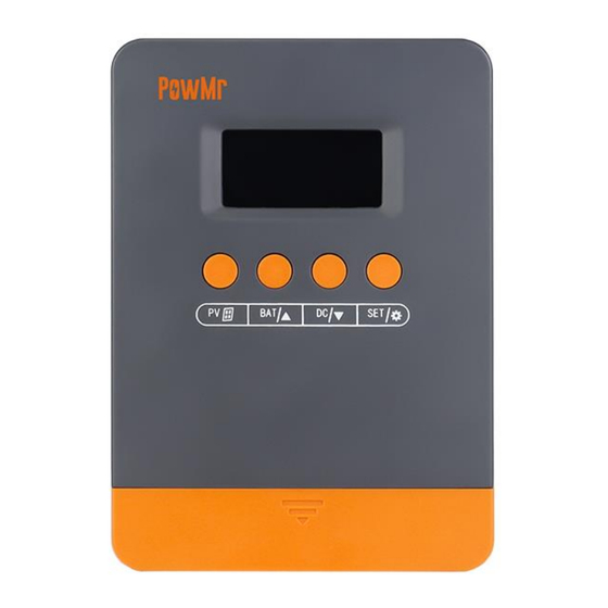
Page 9: Product Appearance
User Manual POW-M Series 1.2 Product Appearance LCD Display Load Interface Function Buttons Port Cover PV Input Interface Heat Sink Battery Interface Mounting Holes... -
Page 10: Installation And Wiring
User Manual POW-M Series 2 Installation and Wiring 2.1 Unboxing and Inspection Before unboxing, check if the packaging is damaged. After unboxing, inspect the contents for any damage or missing items. Inside the package, you will find: ⚫ Controller ⚫ Dedicated Mounting Screws ⚫... -
Page 11: Wiring Precautions
User Manual POW-M Series 2.3 Wiring Precautions 1. Installation and wiring should be carried out by a certified electrician. 2. Follow this sequence when wiring: Battery > PV Input > DC Output. 3. To avoid short circuits and reverse polarity, ensure that the positive (+) cable is connected to the positive (+) terminal of the equipment and the negative (-) cable to the negative (-) terminal. - Page 12 User Manual POW-M Series Step 2. Battery wiring: Connect the battery to the controller using cables. NOTICE ⚫ If an inverter needs to be connected, please refer to the diagram below. NOTICE ⚫ All wiring work must be performed by professionals. ⚫...
- Page 13 User Manual POW-M Series Step 3. PV wiring: Connect the PV array to the controller using cables. Step 4. DC output wiring: Connect the load to the controller using cables. Step 5. Pre-start check: Refer to the wiring diagram below. If all connections are accurate and secure, close the battery and PV array breakers in sequence.
-
Page 14: Operation Guide
User Manual POW-M Series 3 Operation Guide 3.1 Button Introduction Function ① Day/Night Indicator ② Indicates remaining battery power. ③ Operation mode (see "3.3 Operation Mode Description"). ④ Load periodic operation status and alert status (see "4.2 Troubleshooting"). ⑤ Indicates PV input voltage/power. Indicates current battery voltage/charging current/device temperature/battery ⑥... -
Page 15: Key Introduction
User Manual POW-M Series 3.2 Key Introduction Function key Description Browsing Switches PV input parameter information Mode Short press: Switches battery information (to the next option) Browsing Mode BAT/▲ Long press: Enters battery parameter settings Setup Mode Increases the value Switches battery information (to the previous option) Browsing Mode... -
Page 16: Operation Mode Description
User Manual POW-M Series 3.3 Operation Mode Description Code Description Night mode, not charging Fast charging mode (MPPT mode) Boost charging mode Float charging mode Note: In case of a fault, the operation mode section will display the fault code. For details, please refer to section 4.2. -
Page 17: Battery Parameters Overview
User Manual POW-M Series 3.5 Battery Parameters Overview In browse mode, use the BAT/▲ and DC/▼ keys to scroll through the battery parameters. When you reach the parameter you want to set, long press the BAT/▲ key to enter parameter setting mode. -
Page 18: Battery Parameter Settings
User Manual POW-M Series 3.6 Battery Parameter Settings Below are the configurable settings for battery-related parameters: Battery Calibration Voltage When there is a discrepancy between the battery voltage monitored by the controller and the value measured by a multimeter, you can calibrate the battery voltage using this setting. - Page 19 User Manual POW-M Series Custom Configuration of Charging Voltage NOTICE ⚫ If the battery type is set to "USE" (User-defined mode), you can manually adjust the following 5 charging parameters. ⚫ If "USE" is not selected, manual adjustment of charging parameters is not required. The controller will charge based on preset values corresponding to the battery type.
- Page 20 User Manual POW-M Series Float Charging Voltage Setting Interface Default: 13.8V, adjustable range: 9.0~17.0V, step size: 0.1V. Under-voltage Recovery Voltage Setting Interface Default: 12.6V, adjustable range: 9.0~17.0V, step size: 0.1V. Under-voltage Cut-off Voltage Setting Interface Default: 11.0V, adjustable range: 9.0~17.0V, step size: 0.1V.
-
Page 21: Default Parameters For Different Battery Types
User Manual POW-M Series 3.7 Default Parameters for Different Battery Types ◆ For Lead-acid Batteries and User-defined Batteries: Battery Type Parameter Boost Charge Voltage 14.6V 14.2V 14.4V 9.0~17.0V Float Charge Voltage 13.8V 13.8V 13.8V 9.0~17.0V MPP Tracking Return Voltage 13.2V 13.2V 13.2V 9.0~17.0V... - Page 22 User Manual POW-M Series ⚫ Three stages of lead-acid battery charging: Voltage Boost Charging Voltage Float Charging Voltage MPPT Tracking Return Voltage Time Current Bulk Time Boost Float Charging Charging Charging Stage Stage Stage ⚫ Two stages of lithium battery charging: Voltage Boost Charging Voltage MPPT Tracking Return Voltage...
-
Page 23: Protection
User Manual POW-M Series 4 Protection 4.1 Protection Functions Protection Description Photovoltaic array When a short circuit occurs in the photovoltaic array, the controller will short circuit cease charging. Rectifying the short circuit fault will restore operation. The controller limits the battery charging current to the maximum rated Photovoltaic input value. -
Page 24: Troubleshooting
User Manual POW-M Series 4.2 Troubleshooting When a fault occurs, the controller will display a fault signal (as shown in the diagram below) to assist you in identifying solutions. Fault Code Fault Cause Solution Input photovoltaic Increase the number of solar panels or connect them in voltage too low series to raise the photovoltaic input voltage. -
Page 25: Maintenance
User Manual POW-M Series 5 Maintenance We recommend conducting the following checks and maintenance at least twice a year to ensure optimal performance: 1. Ensure the controller is securely mounted in a clean and dry environment. 2. Ensure proper airflow around the controller and clean any dust or debris from the heat sinks. 3. -
Page 26: Specification Parameters
User Manual POW-M Series 6 Specification Parameters Models Solar Input Parameters Max. PV Open-Circuit Voltage 100V Max. Input Power: 300W 420W 540W For 12V System 600W 840W 1080W For 24V System Input Voltage Range: <60V <80V <100V For 12V System <60V <80V <100V... - Page 27 User Manual POW-M Series...
Need help?
Do you have a question about the POW-M25-PRO and is the answer not in the manual?
Questions and answers