Table of Contents
Advertisement
Advertisement
Table of Contents

Related Manuals for PowMr Pstar-30A


Summary of Contents for PowMr Pstar-30A
-
Page 2: Important Safety Instructions
Important Safety Instructions WARNING: CAREFULLY READ AND FOLLOW ALL SAFETY INSTRUCTIONS ⚫ Carefully read the manual before the controller is installed and operated; retain the manual in a safe place for future reference. ⚫ The controller must not be installed or operated by any of the following persons, unless they are under strict instruction and supervision: a. - Page 3 ⚫ Battery DC connections a. Ensure that the DC system is fully shut down/isolated prior to disconnection of any existing cabling and/or new connections are made to the battery/DC system. b. Use flexible multi stranded copper cable with sufficient cross sectional area, inline with an appropriate fuse or circuit breaker;...
-
Page 4: Table Of Contents
Table of Contents Important Safety Instructions ....................1 1 Production Instructions ......................4 1.1 Features ........................5 1.2 Production Overview ....................6 2 Installation and Connection ....................7 2.1 Unpacking and Inspection .................... 7 2.2 Preparing for Installation ....................7 2.3 Things You Need ...................... -
Page 5: Production Instructions
1 Production Instructions Thank you for choosing the Pstar Series of Solar Power Controllers. The controller uses numerical control technology design, LCD display, automatic operation. Its pulse-width modulation (PWM) type battery charging mode, as well as control technology, will greatly extend the battery life. This controller is suitable for the solar energy system (independent system), control the charging and discharging process automatically. -
Page 6: Features
1.1 Features ⚫ Integrated charge presets Integrated charge presets combined with adaptive charge logic are well suited for most common battery types, such as LiFePO4, Gel and flooded lead-acid. ⚫ Flexible Application Automatic identification of 12V/24V/36V/48V system voltage. ⚫ Multi-stage charge algorithm The multi-stage charge algorithm is specifically engineered to optimise each recharge cycle and charge maintenance over extended periods. -
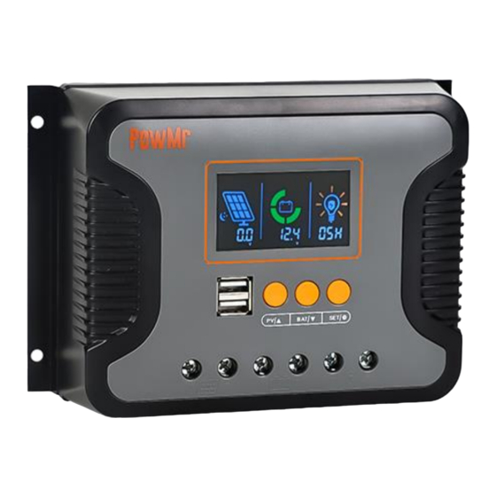
Page 7: Production Overview
1.2 Production Overview LCD display Load port Function keys USB port PV input port Mounting hole (4 x Ø5mm) Battery port Heat sink... -
Page 8: Installation And Connection
2 Installation and Connection 2.1 Unpacking and Inspection Before unpacking the controller, check whether the package is damaged. After unpacking, check whether the contents of the package are damaged or missing. You should have received the following items inside of package: ⚫... -
Page 9: Things You Need
d. Install the controller in a location where it is protected from environmental conditions such as water, high moisture and dust, and also located well away from any flammable liquids or gasses. e. DO NOT install or place/operate the controller on top of the battery, directly above the battery, or in a sealed compartment with the battery;... -
Page 10: Wiring Specification And Breaker Type
Note: The voltage in series shall not exceed maximum PV input open-circuit voltage. ➢ Recommended wire diameter and breaker type for DC output (DC load side): Model Max. DC output Current Wire Diameter Circuit Breaker Spec Pstar-30A 10AWG 2P-20A Pstar-60A 8AWG 2P-35A... -
Page 11: Wiring Precautions
2.6 Wiring Precautions a. Let installation and connection work be done by a licensed electrician. b. To avoid short circuit and reverse polarity connection, ensure that the positive cable is connected to the positive polarity port (+) of the device, and the negative cable is connected to the negative polarity port (-) of the device. -
Page 12: Installation And Connection Step-By-Step
2.7 Installation and Connection Step-By-Step 1. Mark the position of the mounting spots on the wall based on the mount holes of the controller. Then make 4 mounting holes in the wall with an electric drill according to the spots. Refer to the "... - Page 13 5. PV Connection: Connect the PV array to the controller with the cables. 6. DC Output Connection: Connect the load to the controller with the cables. 7. Check before starting up: See figure as shown below for wiring details. If everything is all right, and all the wires are firmly connected, close the circuit breakers at the battery side, PV module side, and load side in sequence to startup controller.
-
Page 14: Operation Mode
3 Operation Mode 3.1 Charge Algorithm The battery charging controller is equipped with an intelligent 3-stage charge characteristic which takes care of an optimal charge of your batteries. When switched on, the Pstar Controller always starts at Bulk stage. 30mins There are 3 integrated charge modes (Bulk, boost, float). -
Page 15: Alarm Function
Any setting made are stored and will not be lost when the controller is disconnected from battery or PV module. The multi-stage charge algorithm includes the individual charge stages described below: ➢ Bulk charge: The battery is charged at maximum charge current until the voltage increases to the configured boost charging voltage. -
Page 16: Operation Instruction
4 Operation Instruction 4.1 Operation Interface Introduction Icon Description LCD Display Indicates the PV input state: daytime state/night state. Indicates the PV input voltage/ PV input current/ PV input power. Indicates the remaining battery capacity. Indicates the current battery voltage/ equipment temperature/ battery calibration voltage/ battery type/ boost charging voltage/ float charging voltage/ low DC cut-off recovery voltage/ low DC cut-off voltage. -
Page 17: Browse And Configuration Parameter Step-By-Step
Function Keys To switch the PV input parameters information/ Return the previous option. To switch the charging information/ Enter the next option. To adjust DC output mode and DC output operation duration/ Confirm and reserve the settings. 4.2 Browse and Configuration Parameter Step-By-Step After cables are connected and the device is started, perform the initial configuration according to the following steps based on the actual situation. - Page 18 4.2.2 Battery side Step 1. Checking Battery Information Press “ ” key to switch battery information, which is current battery voltage, equipment temperature, battery calibration voltage, battery type, boost charging voltage, float charging voltage, low DC cut-off recovery voltage, low DC cut-off voltage in sequence. Current Battery Float Charging Low DC Cut-off...
- Page 19 Step 3. Select the Battery Type Adjust battery type parameters based on the battery you connected: a. Once the parameter switches to the battery type item, press and hold “ ” key to enter the battery type adjustment setting. b. Then press “ ”...
- Page 20 Nominal Boost Float Low DC cut- Low DC cut- system charging charging off recovery off voltage voltage voltage voltage voltage Item Setting Range Nominal system voltage 12V/24V/36V/48V (optional) Boost charging voltage 9~17V Float charging voltage 9~17V Low DC cut-off recovery voltage 9~17V Low DC cut-off voltage 8.4~17V...
-
Page 21: Key Points Of Battery Parameter Settings
⚫ 00H: The solar light control mode. (When the solar energy is sufficient, enable the DC output.) ⚫ 24H: Turn on load immediately. (Default) ⚫ 01H~23H: Adjust the load enable duration. Setting range is from 0 hour to 24 hours. Increment of each click is 1 hour. 4.3 Key Points of Battery Parameter Settings 4.3.1 The logic for setting battery voltage parameters 1) Before you customize battery parameters, confirm the following parameters of the connected... - Page 22 4.3.2 Battery parameters of different types For lead-acid battery & User define: Battery type Parameter Boost charging voltage 14.6V 14.2V 14.4V 14.4V Float charging voltage 13.8V 13.8V 13.8V 13.8V Low DC cut-off voltage 11.0V 11.0V 11.0V 11.0V Low DC cut-off recovery voltage 12.6V 12.6V 12.6V...
-
Page 23: Protection
5 Protection 5.1 Protection Provided Protection Description Fully protected against battery reverse polarity; no damage Battery Reverse Polarity to the controller will result. Correct the miswire to resume normal operation Maximum Charging Ensure safe charging current to prevent battery damage. Current limit Protect battery performance and prolong battery life. -
Page 24: Maintenance
5.3 Maintenance The following inspections and maintenance tasks are recommended at least two times per year for best performance. ⚫ Make sure controller firmly installed in a clean and dry ambient. ⚫ Make sure no block on air-flow around the controller. Clear up any dirt and fragments on heat sink. -
Page 25: Technical Specification
6 Technical Specification Model Pstar-30A Pstar-60A Pstar-80A PV Input Max Open Voltage of PV Module 100V >System voltage and ≤100V PV Operation Voltage Range Max. Input Power: ≤360W ≤720W ≤960W For 12V system ≤720W ≤1440W ≤1920W For 24V system ≤1080W ≤2160W...
Need help?
Do you have a question about the Pstar-30A and is the answer not in the manual?
Questions and answers