Table of Contents
Advertisement
Advertisement
Table of Contents

Related Manuals for PowMr POW-M80 Series


Summary of Contents for PowMr POW-M80 Series
- Page 1 User Manual POW-M80 & POW-M100 Series...
-
Page 2: Important Safety Instructions
User Manual POW-M80 & POW-M100 Series Important Safety Instructions WARNING: Carefully read and adhere to all safety instructions. ➢ Before installing and operating the controller, please read the user manual thoroughly and keep it for future reference. ➢ The installation or operation of the controller should only be performed by individuals who have received proper training and supervision. - Page 3 User Manual POW-M80 & POW-M100 Series d. Do not charge non-rechargeable batteries. Do not charge lithium batteries when the temperature is below 0°C. Charging frozen batteries is prohibited. e. Ensure that the equipment is properly configured for the type of battery connected to it. DC Battery Connections a.
- Page 4 User Manual POW-M80 & POW-M100 Series Declaration Under the following circumstances, our company reserves the right not to assume any quality warranty responsibilities: ⚫ Damage caused by improper transportation. ⚫ Damage resulting from incorrect storage, installation, or usage. ⚫ Damage caused by non-professionals or untrained personnel installing and operating the equipment.
-
Page 5: Table Of Contents
User Manual POW-M80 & POW-M100 Series Table of contents Important Safety Instructions..........................1 1 Product Introduction ............................4 1.1 Features ..............................5 1.2 Product Appearance ..........................7 2 Installation and Wiring ............................8 2.1 Unpacking and Inspection ........................8 2.2 Choosing the Installation Location ....................8 2.3 Wiring Precautions .......................... -
Page 6: Product Introduction
User Manual POW-M80 & POW-M100 Series 1 Product Introduction Welcome to the POW-M80 and POW-M100 series solar controllers, representing cutting-edge innovation in the field of solar technology. Designed to deliver outstanding performance and reliability to your solar system, our meticulously crafted controllers feature advanced CNC technology, an LCD screen, and user-friendly button design, expanding configuration capabilities for real-time monitoring of operational data and system status. -
Page 7: Features
User Manual POW-M80 & POW-M100 Series 1.1 Features ⚫ Integrated Charging Presets Integrated charging modes include adaptive charging logic, suitable for most battery types such as flooded lead-acid batteries, gel-sealed lead-acid batteries, and lithium batteries. Specific charging parameters for each battery type can be found in Section 3.5. ⚫... - Page 8 User Manual POW-M80 & POW-M100 Series c. Reversed photovoltaic polarity d. Overvoltage protection for batteries e. Overdischarge protection for batteries f. Over-temperature protection ⚫ External Temperature Probe Configuration Enhance precision in battery temperature monitoring by configuring an external temperature probe. This ensures accurate temperature compensation for optimal system performance. ⚫...
-
Page 9: Product Appearance
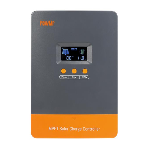
User Manual POW-M80 & POW-M100 Series 1.2 Product Appearance LCD Display Screen Temperature Probe Port Function Keys Parallel Communication Port Photovoltaic Input Interface Port Cover Plate Battery Interface Heat Dissipation Vent... -
Page 10: Installation And Wiring
User Manual POW-M80 & POW-M100 Series 2 Installation and Wiring 2.1 Unpacking and Inspection Before unpacking, inspect the packaging for any signs of damage. After unpacking, check the contents to ensure nothing is damaged or missing. Inside the package, you will find the following items: ⚫... -
Page 11: Wiring Precautions
User Manual POW-M80 & POW-M100 Series 2.3 Wiring Precautions 1. Installation and wiring work should be carried out by a certified electrician. 2. Wiring should follow the sequence of Battery > PV Input. 3. To avoid short-circuits and polarity reversal, pay attention to connecting the positive (+) cable to the device's positive (+) terminal and the negative (-) cable to the device's negative (-) terminal. - Page 12 User Manual POW-M80 & POW-M100 Series Step 2. Battery Wiring: Connect the battery to the controller using cables. ATTENTION ⚫ If an inverter connection is required, please refer to the diagram below. NOTE ⚫ All wiring work must be carried out by professionals. ⚫...
- Page 13 User Manual POW-M80 & POW-M100 Series Step 3. PV Wiring: Connect the photovoltaic array to the controller using cables. Step 4. Temperature Probe Connection: Connect the temperature probe wire to the controller and securely fix the probe end to the battery using insulation tape. Step 5.
-
Page 14: Operation Guide
User Manual POW-M80 & POW-M100 Series 3 Operation Guide 3.1 Operation Interface Overview Display Interface 功能 ① Day/Night Indicator Icon, indicating the presence of photovoltaic input ② Battery Remaining Capacity Indicator ③ Charging in Progress Indicator ④ Photovoltaic Input Voltage/Power/Operating Mode/Fault Codes Current Battery Voltage/Charging Current/Device Temperature/Battery Calibration ⑤... - Page 15 User Manual POW-M80 & POW-M100 Series Button Functions Button Description Browsing Switch photovoltaic input parameters Mode PV/SET Setup Mode Confirm settings Short Press: Switch battery parameters, move to the next Browsing item Mode BAT/▲ Long Press: Enter battery parameter settings Increase value/return to the previous item and move to the Setup Mode next...
-
Page 16: Overview Of Photovoltaic Parameters
User Manual POW-M80 & POW-M100 Series 3.2 Overview of Photovoltaic Parameters A short press of the PV/SET key will result in the following data switching on the left side of the display page: PV Input Voltage PV Input Power Operating Mode/Fault Codes ... -
Page 17: Overview Of Battery Parameters
User Manual POW-M80 & POW-M100 Series 3.3 Overview of Battery Parameters In browsing mode, use the BAT/▲ and BAT/▼ keys to scroll through battery parameters. When switching to the parameter that needs adjustment, long-press the BAT/▲ key to enter the parameter setting mode. -
Page 18: Battery Parameter Settings
User Manual POW-M80 & POW-M100 Series 3.4 Battery Parameter Settings The following are configurable settings for battery-related parameters. Calibrated Battery Voltage When there is a difference between the battery voltage monitored by the controller and the value measured by a multimeter, the battery voltage can be calibrated using this setting. - Page 19 User Manual POW-M80 & POW-M100 Series Battery Type Setting Please refer to the table below and choose the battery type based on the connected batteries: Order Display Battery Type Sealed Lead-Acid Battery Gel Sealed Lead-Acid Battery Flooded Lead-Acid Battery 4-Series LiFePO4 Battery 7-Series LiFePO4 Battery 8-Series LiFePO4 Battery 15-Series LiFePO4 Battery...
- Page 20 User Manual POW-M80 & POW-M100 Series Custom Configuration of Charging Voltage NOTE ⚫ If the battery type is selected as "USE" (User-defined mode), then the five charging parameters in the diagram below can be manually set. ⚫ If "USE" is not selected, there is no need to manually set charging parameters.
-
Page 21: Default Parameters For Different Battery Types
User Manual POW-M80 & POW-M100 Series 3.5 Default Parameters for Different Battery Types ◆ For Lithium-Ion Batteries and User-defined Batteries: Battery Type Parameters Boost Charging Voltage 14.6V 14.2V 14.4V 9.0~17.0V Float Charging Voltage 13.8V 13.8V 13.8V 9.0~17.0V MPP Tracking Return Voltage 13.2V 13.2V 13.2V... -
Page 22: Protection
User Manual POW-M80 & POW-M100 Series 4 Protection 4.1 Protection Function Protection Explanation In the event of a short circuit in the photovoltaic array, the controller Photovoltaic Array will cease charging. Resolving the short circuit fault will restore normal Short Circuit operation. -
Page 23: Troubleshooting
User Manual POW-M80 & POW-M100 Series 4.2 Troubleshooting When a fault occurs, the controller will display a fault code to assist you in finding a solution. Fault Code Possible Causes Solutions Increase the number of solar panels or connect Low input them in series to raise the photovoltaic input photovoltaic voltage voltage. -
Page 24: Maintenance
User Manual POW-M80 & POW-M100 Series 5 Maintenance We recommend conducting the following checks and maintenance at least twice a year to ensure optimal performance: 1. Ensure the controller is securely mounted in a clean and dry environment. 2. Ensure proper airflow around the controller and clean any dust or debris from the heat sinks. 3. -
Page 25: Specification Parameters
User Manual POW-M80 & POW-M100 Series 6 Specification Parameters Models 100A Solar Input Specification Max. Solar Array Open-Circuit 160V Voltage Maximum Input Power: For 12V System 960W 1200W For 24V System 1920W 2400W For 36V System 2880W 3600W For 48V System 3840W 4800W Battery Charging Specification... -
Page 26: Parallel Operation Guide
User Manual POW-M80 & POW-M100 Series 7 Parallel Operation Guide Parallel Operation Schematic Solar array 1 Solar array 2 Solar array n …… …… Parallel Communication Cable Battery Pack Positive Power Cable Negative Power Cable Main Modules: ➢ Controller The controller device is designed for both standalone and parallel operation. In parallel operation, communication between controllers is achieved through communication lines. - Page 27 User Manual POW-M80 & POW-M100 Series Parallel Installation and Wiring You can view the parallel operation guide by scanning the QR code in the upper right corner. Step 1. Install parallel devices at the same height level with a minimum distance of approximately 75mm between devices.
- Page 28 User Manual POW-M80 & POW-M100 Series...
Need help?
Do you have a question about the POW-M80 Series and is the answer not in the manual?
Questions and answers