Table of Contents
Advertisement
Quick Links
Advertisement
Table of Contents

Subscribe to Our Youtube Channel
Related Manuals for PowMr POW-Boost 10A


Summary of Contents for PowMr POW-Boost 10A
-
Page 2: Important Safety Instructions
Important Safety Instructions WARNING: CAREFULLY READ AND FOLLOW ALL SAFETY INSTRUCTIONS ⚫ Carefully read the manual before the controller is installed and operated; retain the manual in a safe place for future reference. ⚫ The controller must not be installed or operated by any of the following persons, unless they are under strict instruction and supervision: a. - Page 3 ⚫ Battery DC connections a. Ensure that the DC system is fully shut down/isolated prior to disconnection of any existing cabling and/or new connections are made to the battery/DC system. b. Use flexible multi stranded copper cable with sufficient cross sectional area, inline with an appropriate fuse or circuit breaker.
-
Page 4: Table Of Contents
Table of Contents Important Safety Instructions ..................1 1 General Information ....................4 1.1 Function ......................5 1.2 Product Overview ....................7 1.3 Product Dimension ..................... 8 2 Installation ........................10 2.1 Unpacking and Inspection ................10 2.2 Preparing for Installation .................. 10 2.3 Installation Steps .................... -
Page 5: General Information
General Information 1 General Information The core of the PowMr Boost-Type Solar Charge Controller lies in its adoption of cutting-edge boost converter circuitry. This sophisticated circuit intelligently elevates the voltage output from solar panels and matches the optimal charging voltage for batteries. By precisely adjusting the voltage, the controller maximizes energy transfer efficiency, capturing every available watt of solar power. -
Page 6: Function
1.1 Function ⚫ Boost Voltage Charging Controller Designed for scenarios where the photovoltaic input voltage is lower than the battery voltage, this controller effectively boosts the voltage to match the battery's charging requirements. It overcomes limitations caused by insufficient voltage from a single photovoltaic panel, ensuring reliable battery charging. - Page 7 protected state, the controller will activate the lithium battery using the energy from the solar panel with a current that does not exceed the lithium battery's protection voltage and current range. Warning: Do not charge Li-ion batteries if the battery temperature is below 0° C.
-
Page 8: Product Overview
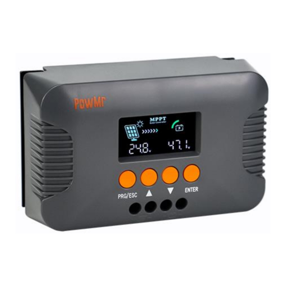
1.2 Product Overview 1. LCD display 2. Function Keys 3. PV Input port 4. Battery port 5. Install holes 6. Heat sink... -
Page 9: Product Dimension
1.3 Product Dimension NOTICE ⚫ Dimensional measurement tolerance is ±0.5mm. -
Page 10: Installation
Installation 2 Installation 2.1 Unpacking and Inspection Before unpacking the controller, check whether the package is damaged. After unpacking, check whether the contents of the package are damaged or missing. You should have received the following items inside of package: ⚫... -
Page 11: Installation Steps
d. Install the controller in a location where it is protected from environmental conditions such as water, high moisture and dust, and also located well away from any flammable liquids or gasses. e. DO NOT install or place/operate the controller on top of the battery, directly above the battery, or in a sealed compartment with the battery;... -
Page 12: Connection
Connection 3 Connection 3.1 Things You Need Make sure you have all the parts you need to install and connect the Pstar Controller: Item Quantity Controller (included) DC-cable to connect the positive DC connection (+) of the Pstar Controller to the positive polarity of DC input or DC output... -
Page 13: Connection Steps
photovoltaic and battery ends, ensuring that the positive (+) terminal is connected to the positive (+) terminal and the negative (-) terminal is connected to the negative (-) terminal. 8. Keep each circuit breaker in the open position during the wiring process. 9. -
Page 14: Operation
Operation 4 Operation 4.1 Operation Interface Introduction Icon Description LCD display 1. On the main screen, display the photovoltaic input data and operating mode. ① 2. In the settings interface, display the setting options. 3. In the event of a fault state, display "ERR". 1. -
Page 15: Viewing And Configuration Guide For Parameters
4.2 Viewing and Configuration Guide for Parameters After successfully starting the device, please refer to the following guide to view and configure the controller parameters based on your specific requirements. 4.2.1 Browsing Interface Data On the main interface, use the " "... - Page 16 When the battery voltage drops to this value, the Return-to-MPPT Charging controller will enter a new charging cycle to charge Voltage the battery. The maximum charging current of the controller. Maximum Charging Current Set according to the charging parameters of the connected battery.
- Page 17 Lithium iron phosphate battery: Voltage control Float charging Boost reconnect Boost charging voltage parameters voltage charging voltage 25.2V 24.5V 22.4V 28.8V 25.6V 39.6V 38.5V 35.2V 43.2V 38.4V 52.5V 57.6V 51.2V 64.8V 57.6V 68.4V 66.5V 60.8V 79.2V 70.4V 82.8V 80.5V 73.6V For Ternary lithium battery: Voltage control Boost charging...
-
Page 18: Protection And Troubleshooting
Protection and Troubleshooting 5 Protection and Troubleshooting 5.1 Protection Protection Description Fully protected against reverse polarity; no damage to the Reverse Polarity controller will result. Correct the miswire to resume normal operation Maximum Charging Ensure safe charging current to prevent battery damage. Current limit Protect battery performance and prolong battery life. -
Page 19: Maintenance
5.3 Maintenance The following inspections and maintenance tasks are recommended at least two times per year for best performance. ⚫ Make sure controller firmly installed in a clean and dry ambient. ⚫ Make sure no block on air-flow around the controller. Clear up any dirt and fragments on heat sink. -
Page 20: Technical Specification
Technical Specification 6 Technical Specification Model POW-Boost 10A PV Input PV Input Voltage 15~25V 25~48V 48~60V PV Input Power ≤150W ≤250W ≤400W System Voltage 48/60/72V 60/72V 24/36/48/60/72V Charging Mode Charging technology MPPT Charge Algorithm 3-Stage Self-consumption <2W Nominal System Voltage...
Need help?
Do you have a question about the POW-Boost 10A and is the answer not in the manual?
Questions and answers