
Related Manuals for PowMr M2430ND


Summary of Contents for PowMr M2430ND
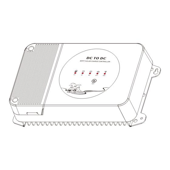
- Page 1 Solar DC-DC Buck-Boost Controller M2430ND User Manual *We may modify these specifications without prior notice.
-
Page 2: Safety Tips
1. Warnings and Tools Icon Chart 2. Safety Tips · It is very important to review this manual thoroughly before attempting Icons Name Description installation. · Beware of any nearby electrical equipment that may interfere with High voltage device. installing this device. Installation should be High Voltage And please don’t plug in any AC source to this DC-DC product, or it may cause... -
Page 3: Product Features
Thank you for choosing our product. This device is a DC-DC intelligent charger/ controller for vehicle or similar systems with dual batteries. Applied in a dual M2430ND battery system, this charger combines respective advantages of motor (ordinary/smart alternator) power generation and photovoltaic power generation. -
Page 4: Mounting Instruction
5. Mounting Instruction 5.5 After connecting the wires, cover the mounting cover plate and tighten the screws. 5.1 Wire preparation. 5.6 Fixed. 5.6.1 Placement. This device adopts vertical heat dissipation, so it needs to be placed horizontally when it is fixed, so that the hot air can desperse smoothly. 150mm 5.2 Remove the mounting cover plate. - Page 5 7.Working Process Introduction 6.2 The Alternator directly connected to the starter battery. 6.2.1 Smart Alternator. 7.1 System operating battery identification. The alternator will lead out the IGN signal line after starting. When the signal line is detected, the machine will detect the voltage of the starter Dawn battery.
- Page 6 7.4 Switching logic between battery 1 and battery 2 during normal 7.6 MPPT Charging. operation . (battery without load) (take 12V system as an example) MPPT is the abbreviation of Maximum Power Point tracking. Since the photovoltaic curve has the following characteristics, it is hoped that the following Work Point can be Start tracked when the photovoltaic energy is used for charging.
- Page 7 7.7.2 The change of light intensity to photovoltaic curve. (weak light on the left and External Input Not Charging strong light on the right) Steady On External Input Detected & DC-DC Charging Work Point Work Point Regular Alternator Not Connected Steady On Regular Alternator Charging Check the Fault light for possible system errors.
-
Page 8: Product Dimension
12. Controller Specification Attached Table 2 The variable “n” is adopted as a multiplying factor when calculating parameter voltages, SEL/AGM LFP12 LFP24 the rule for “n” is listed as: if battery system voltage is 12V, n=1; 24V, n=2. For example, the equalize charge voltage for a 12V FLD (Flooded) battery bank is 14.8V*1=14.8V. - Page 9 Battery 1 Battery Service Battery 12/24V AUTO Battery System Voltage Battery Voltage Range 8V-32V Battery Type GEL/SEL/FLD/USE/LI Max Current Battery 2 Battery Starter Battery Battery System Voltage 12/24V AUTO Battery Voltage Range 8V-32V Battery Type GEL/SEL/FLD/USE/LI Max Current Charging Mode Buck MPPT+CC+CV Max Solar Input Power 450W / 900W...
Need help?
Do you have a question about the M2430ND and is the answer not in the manual?
Questions and answers