Sign In
Upload
Download
Table of Contents
Contents
Add to my manuals
Delete from my manuals
Share
URL of this page:
HTML Link:
Bookmark this page
Add
Manual will be automatically added to "My Manuals"
Print this page
×
Bookmark added
×
Added to my manuals
Manuals
Brands
PowMr Manuals
Controller
Keeper Series
Manual
PowMr Keeper Series Manual
Maximum power point tracking solar charge controller
Hide thumbs
1
Table Of Contents
2
3
4
5
6
7
8
9
10
11
12
13
14
15
page
of
15
Go
/
15
Contents
Table of Contents
Bookmarks
Advertisement
Table of Contents
1
Table of Contents
2
Overview
3
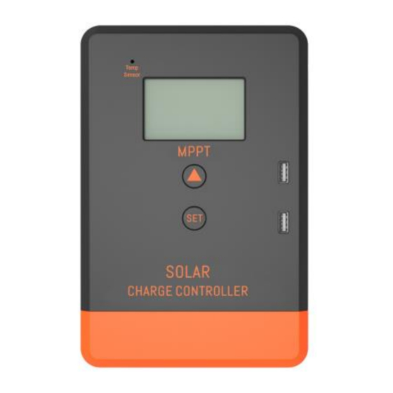
Product Appearance
4
Wiring
5
Descrlptlon
6
Installation Important Note
7
Operation Steps
8
Protection
9
Common Fault
10
Technical Specifications
Download this manual
1
Table of
Contents
Previous
Page
Next
Page
1
2
3
4
5
Advertisement
Table of Contents
Need help?
Do you have a question about the Keeper Series and is the answer not in the manual?
Ask a question
Questions and answers
Related Manuals for PowMr Keeper Series
Controller PowMr Keeper1220 Manual
Maximum power point tracking solar charge controller (15 pages)
Controller PowMr Keeper MPPT 20A-40A Manual
Maximum power point tracking solar charge controller (26 pages)
Controller PowMr MPPT-60A User Manual
Solar charge controller (16 pages)
Controller PowMr POW-M80 Series User Manual
(28 pages)
Controller PowMr POW-M25-PRO User Manual
Solar charge controller (27 pages)
Controller PowMr Pstar-30A User Manual
Solar charge controller (26 pages)
PowMr SOLAR60, SOLAR80 (S30, S80, S60) Manual
(article)
Controller PowMr M2430ND User Manual
Solar dc-dc buck-boost controller (9 pages)
Controller PowMr POW-M60-PRO User Manual
Solar charge controller (29 pages)
Controller PowMr 615150291644 Manual
60a solar charge controller (1 page)
Controller PowMr POW-Boost 10A User Manual
Solar charge controller (21 pages)
Controller PowMr M1210P User Manual
Mppt solar charge controller (2 pages)
Controller PowMr SOLAR60 User Manual
Solar charging and discharging controller (3 pages)
Controller PowMr POW-48140A User Manual
Solar charge controller (25 pages)
Controller PowMr RV-2430 User Manual
Solar dc-dc buck-boost controller (11 pages)
This manual is also suitable for:
Keeper1220
Keeper1230
Keeper1240
Table of Contents
Save PDF
Print
Rename the bookmark
Delete bookmark?
Delete from my manuals?
Login
Sign In
OR
Sign in with Facebook
Sign in with Google
Upload manual
Upload from disk
Upload from URL


Need help?
Do you have a question about the Keeper Series and is the answer not in the manual?
Questions and answers