
Related Manuals for sauter EQJW 246


Summary of Contents for sauter EQJW 246
- Page 1 Shortmanual EQJW246F003 P100020315 Heating and District Heating Controller with graphics display Firmwareversion 3.02.01...
- Page 2 These mounting and operating instructions assist you in mounting and operating the device safely. The instructions are binding for handling SAUTER devices. A manual with further information can be found at www.sauter-controls.com Î For the safe and proper use of these instructions, read them carefully and keep them for later reference.
-
Page 3: Table Of Contents
Inhalt Liability ..................4 Safety instructions ..............4 Structure and mode of action ............ 5 Dimensions ................6 Installation ................7 Electrical connection ..............8 Control elements ..............12 Operation ................13 Selecting the operating mode ..............13 Schedules .................... 15 8.2.1 Setting the time and date ............... -
Page 4: Liability
Liability 1 Liability We are constantly developing our products and therefore, reserve the right to change the product at any time without notice. We assume no liability for the correctness or completeness of this quick guide. No liability is accepted for the purchaser being able to use the products for a specific purpose. Claims by the purchaser, in particular claims for damages including loss of profit or other financial losses, are excluded. -
Page 5: Structure And Mode Of Action
Structure and mode of action 3 Structure and mode of action The EQJW246F003 heating and district heating controller is used to control up to three control circuits. Control of a primary heat exchanger or boiler with up to two mixed and one unmixed –... -
Page 6: Dimensions
Dimensions 4 Dimensions Panel cutout 138 x 92 EQJW246F003... -
Page 7: Installation
Installation 5 Installation Panel mounting wall mounting Rail mounting EQJW246F003... -
Page 8: Electrical Connection
Electrical connection 6 Electrical connection DANGER Danger to life from electric shock! − When wiring and connecting the heating and district heating controller, the VDE regula- tions and the regulations of the local energy supply companies must always be obser- ved. - Page 9 Electrical connection Overvoltage protection − If signalling cables are laid outside buildings or over long distances, take suitable overvoltage protection measures. Such measures are essential for bus cables. − The shielding of signalling cables that are laid outside buildings must be cur- rent-carrying and earthed on both sides.
- Page 10 Electrical connection Bild 1: Connection of SAUTER EQJW246F003 Controller with standard base EQJW246F003...
- Page 11 Electrical connection Legend to picture 1: Analog output PWM Puls width modulation Storage tank charging pump Analog input Room sensor Circulation pump Outdoor sensor Heating circuit Flow sensor Binary output RüF Return flow sensor Circulation pump Binary input Storage sensor Remote sensor EQJW246F003...
-
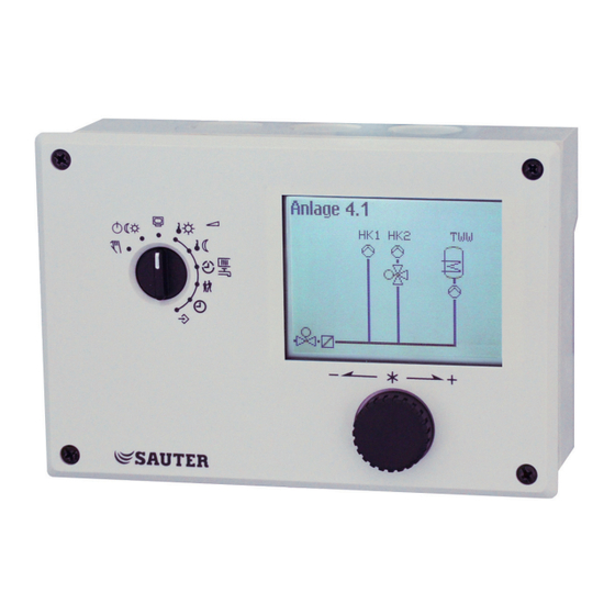
Page 12: Control Elements
Operating controls 7 Operating controls The heating controller is operated on site using the operating controls on the front. They are located in the front panel of the controller. Rotary pushbutton Turn [q]: Select readings, parameters and function blocks Press [Û]: Confirm adjusted selection or setting Rotary switch The rotary switch is used to set the operating mode and the relevant parameters for each... -
Page 13: Operation
Operation 8 Operation 8.1 Selecting the operating mode The controller can be operated in the following modes: Day mode (rated operation): regardless of the programmed times-of-use and sum- mer mode, the set points relevant to rated operation are used by the controller. Icon: Night mode (reduced operation): regardless of the programmed times-of-use, the set points relevant to reduced operation are used by the controller. -
Page 14: Schedules
Operation ¼ Activate editing mode for the control circuit. The oper- ating mode is shown inverted on the display. q Select the operating mode: Automatic mode Day mode Night mode System deactivated ¼ Confirm the operating mode. The controller is usually in automatic mode. 8.2 Schedules The controller operates according to the schedules in automatic mode. -
Page 15: Setting The Time And Date
Operation ¼ Activate editing mode for the time. The time reading is inverted. q Change the time. ¼ Confirm the time setting. q Select 'Date' (dd.mm) [q]. ¼ Activate editing mode for the date. The date reading is inverted. q Change date (day.month). ¼... -
Page 16: Setting The Times-Of-Use
Operation q Select 'Auto summertime'. ¼ Activate the editing mode for automatic summer/stan- dard time switchover. The current setting is shown in- verted on the display: ON = Summer/standard time switchover active OFF = Summer/standard time switchover not active q Deactivate or activate the automatic summer/standard time switchover. - Page 17 Operation Turn the rotary switch to (times-of-use). The first control circuit is displayed together with its programmed times-of- use. q Program the times-of-use of another control circuit, if re- quired: – Heating circuit HC2 – Heating circuit HC3 – Heating circuit HC11 –...
- Page 18 Operation ¼ Activate editing mode for the period/day. The start time of the first time-of-use period can now be edited (inverted reading). q Change start time. (in steps of 15 minutes) ¼ Confirm the start time. The stop time of the first time-of-use period can now be edited.
-
Page 19: Entering Day And Night Set Points
Operation 8.3 Entering day and night set points The day set points apply during day mode (rated operation) and during times-of-use pro- grammed for automatic mode. The night set points apply during night mode (reduced operation) and outside the times-of- use programmed for automatic mode. - Page 20 Operation Switch position Parameters Value range HC1 OT deactivation value 15.0 °C –50.0 to 50.0 °C HC2 OT deactivation value 15.0 °C –50.0 to 50.0 °C HC3 OT deactivation value 15.0 °C –50.0 to 50.0 °C HC11 OT deactivation value 15.0 °C –50.0 to 50.0 °C HC12 OT deactivation value 15.0 °C –50.0 to 50.0 °C HC13 OT deactivation value...
-
Page 21: Reset To Default Settings
Operation Turn the rotary switch to (day set point) or (night set point). The day and night set points appear on the display one after the other. Î Only those day and night set points are available for selection which can be controlled by the selected sys- tem. -
Page 22: Reading Information
Operation 8.5 Reading information Different kinds of information can read off the controller display during operation. The controller display usually shows the date, time and an actual temperature when the rotary switch is switched to the 'Operating level' position. Outdoor-temperature-compensated control · Current temperature = out- door temperature Deactivation depending on Vacations active... - Page 23 Operation q Operating state The following applies for heating circuits HC1, HC2, HC3, HC11, HC12 and HC13: Current op. Current position- mode ing value Heating Valve Circulation pump circuit opens (heating) ON/OFF closes The following applies for DHW heating: Current operating mode Pump ON/OFF Storage tank charging...
- Page 24 Operation q Times-of-use (depending on the system code number) – Heating circuit HC1 – Heating circuit HC2 – Heating circuit HC3 – Heating circuit HC11 – Heating circuit HC12 – Heating circuit HC13 – DHW heating The day mode times is highlighted in black on the time chart.
- Page 25 Operation q Trend-Viewer The standard graph shows the data measured at the outdoor sensor AF1 and flow sensor VF1 plotted over time. Extended operating level The following details on the controller version (device identification, serial number, software and hardware versions) and meter bus are displayed in the extended operating level.
-
Page 26: Adapting The Trend-Viewer
Operation Note − The additional information is hidden when the key number 1999 is entered again. − The key number 1999 cannot be used to change the controller configuration and parameterization. A separate key number exists for configuration and parameterization (see the 'Start-up' section). 8.5.1 Adapting the Trend-Viewer The standard graph shows the data measured at the outdoor sensor AF1 and flow sensor VF1 plotted over time. - Page 27 Operation ¼ Confirm setting. Deleting measured data: q Select the sensor whose measured data are no longer to be displayed. ¼ Activate editing mode for sensor. q Select – – – – on the display. ¼ Confirm deletion. Shifting the time line: q Select 'Scroll'.
-
Page 28: Operating The Controller In Manual Mode
Operation 8.6 Operating the controller in manual mode Switch to manual mode to configure all controller outputs. NOTICE System damage caused by frost when manual operating mode is active! The frost protection function is deactivated in the manual operating mode. Î... -
Page 29: Error List
Error list 9 Error list Sensor failure = Sensor failure (see the 'Malfunctions' section in the Mounting and Operating Instructions u EQJW246F003) Disinfection = Disinfection temperature not reached. See 'Thermal dis- infection of DHW storage tank' function in Annex A (configuration instructions) of the Mounting and Operat- ing Instructions u EQJW246F003. -
Page 30: Technical Data
Technical data 10 Technical data Inputs 14x sensor inputs Pt 1000, PTC or Ni 1000, alternatively configurable for binary signals 3x inputs for 0 to 10 V Input 17 for a 3 to 800 lmp/h pulse signal from a heat meter meter for power limitation in HC1 configurable Outputs 3x three-point signal, alternatively 3x two-point signal:... - Page 31 Technical data EQJW246F003...
- Page 32 EQJW246F003 SAUTER Deutschland Sauter-Cumulus GmbH Hans-Bunte-Str. 15 79108 Freiburg http://www.sauter-cumulus.de Telefon +49 (761) 5105-0 Telefax +49 (761) 5105-234 D100523804 26.06.2024 E-Mail: sauter-cumulus@de.sauter-bc.com...
Need help?
Do you have a question about the EQJW 246 and is the answer not in the manual?
Questions and answers