
Related Manuals for sauter RDT 921 F901


Summary of Contents for sauter RDT 921 F901
- Page 1 Sauter Italia S.p.A. RDT921F901 | Hardware manual ver. 1.0 | Code 114RDT921E104SAU RDT 921 F901 Configurable controllers Hardware manual | ENGLISH Code 114RDT921E104SAU page 1 of 38...
- Page 2 Sauter Italia S.p.A. RDT921F901 | Hardware manual ver. 1.0 | Code 114RDT921E104SAU Important Read this document thoroughly before installation and before use of the device and follow all recommendations; keep this document with the device for future consultation. Only use the device in the way described in this document; do not use the same as a safety device.
-
Page 3: Table Of Contents
Sauter Italia S.p.A. RDT921F901 | Hardware manual ver. 1.0 | Code 114RDT921E104SAU Index INTRODUCTION ..........5 Introduction ............ 5 DESCRIPTION ..........6 Description ............. 6 DIMENSIONS AND INSTALLATION ..... 7 Dimensions: ............ 7 Installation............7 Installation warnings ........8 ELECTRIC CONNECTION ........9 Connectors ............. - Page 4 Sauter Italia S.p.A. RDT921F901 | Hardware manual ver. 1.0 | Code 114RDT921E104SAU page 4 of 38...
-
Page 5: Introduction
Sauter Italia S.p.A. RDT921F901 | Hardware manual ver. 1.0 | Code 114RDT921E104SAU INTRODUCTION Introduction RDT900 is a range of configurable controllers for cooling and air conditioning applications. The controllers are equipped with a significant number of input and output arrangements which make it possible to create a flexible, modular and expandable network of control devices. -
Page 6: Description
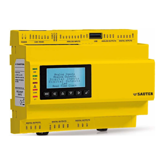
Sauter Italia S.p.A. RDT921F901 | Hardware manual ver. 1.0 | Code 114RDT921E104SAU DESCRIPTION Description The following drawing shows the appearance of the devices. The following table shows the meaning of the parts of the devices. PART MEANING K1 and K2 digital outputs... -
Page 7: Dimensions And Installation
Sauter Italia S.p.A. RDT921F901 | Hardware manual ver. 1.0 | Code 114RDT921E104SAU DIMENSIONS AND INSTALLATION Dimensions: The following drawing shows the measurements of the devices (8 DIN modules), in mm (in). Installation The device is installed on a DIN 35.0 x 7.5 mm (1.377 x 0.295 in) or 35.0 x 15.0 mm (1.377 x 0.590 in), track in a control panel. -
Page 8: Installation Warnings
Sauter Italia S.p.A. RDT921F901 | Hardware manual ver. 1.0 | Code 114RDT921E104SAU To remove the devices, first remove any screw-in removable terminal boards mounted in the lower part, then trigger the DIN track clip with a screwdriver as show in the following picture: To install the devices again, first press the clip of the DIN track. -
Page 9: Electric Connection
Sauter Italia S.p.A. RDT921F901 | Hardware manual ver. 1.0 | Code 114RDT921E104SAU ELECTRIC CONNECTION Connectors The following drawing shows the connectors of the devices. Meaning of connectors The following tables show the meaning of the various device connectors. For additional information, please read chapter 7 "TECHNICAL DATA",... - Page 10 Sauter Italia S.p.A. RDT921F901 | Hardware manual ver. 1.0 | Code 114RDT921E104SAU analog input 3 settable by way of the PTC, NTC, Pt 1000, Ni 1000 probes configuration parameter, transducers 0-20 mA, 4-20 mA, 0-5 V ratiometric o 0-10 V...
- Page 11 Sauter Italia S.p.A. RDT921F901 | Hardware manual ver. 1.0 | Code 114RDT921E104SAU DIGITAL OUTPUTS Digital outputs. PART MEANING common digital output 1 usually open contact for digital output 1 according to model: electromechanical relay with 3 A res. @ 250 VAC control for 24 VAC/DC, 600 mA max.
- Page 12 The RS-485 MODBUS slave and RS-485 MODBUS master/slave ports can be used for one of the following operations: device configuration (through the Parameters Manager set-up software system) device supervision (through the Sauter Vision Center system monitoring and supervision (via Web) system) MODBUS master function use with regard to other slave devices.
-
Page 13: Insertion Of The Termination Resistor Of The Can Canbus Port
Sauter Italia S.p.A. RDT921F901 | Hardware manual ver. 1.0 | Code 114RDT921E104SAU ETHERNET Ethernet MODBUS TCP, Web Server, BACnet IP port Please see paragraph 6 "CONFIGURATION" for the settings of the Ethernet MODBUS TCP, Web Server, BACnet IP port. Insertion of the termination resistor of the CAN CANBUS port To reduce reflections on the signal transmitted through the cables connecting the devices to a CAN network it is necessary to insert the termination resistor of the first and last elements of the network. -
Page 14: Example Of Electric Connection
CAN network using a twisted pair position the power cables as far away as possible from the signal cables do not use the device as a safety device for repairs and information regarding the device, contact the SAUTER ITALIA sales network. page 14 of 38... -
Page 15: User Interface
Sauter Italia S.p.A. RDT921F901 | Hardware manual ver. 1.0 | Code 114RDT921E104SAU USER INTERFACE Keypad The following table shows the meaning of the keypad of the devices. PRESET FUNCTION cancel, hereinafter also "ESC key" left shift, hereinafter also "LEFT key"... - Page 16 Sauter Italia S.p.A. RDT921F901 | Hardware manual ver. 1.0 | Code 114RDT921E104SAU CAN CANBUS communication LED if it is on, the device is configured to communicate via CAN CANBUS with another device, but the communication has not been established if it is flashing slowly, the CAN CANBUS communication has been established, but is not entirely correct...
-
Page 17: Configuration
To access the procedure, proceed as follows: Check that the power is on. Keep the UP and DOWN keys pressed for 2 s: the following menu (hereinafter, the "Main menu") shall appear on the display, <RDT 921 F901> Info English Parameters... -
Page 18: Configuration Of A Controller Through A Remote User Interface
Sauter Italia S.p.A. RDT921F901 | Hardware manual ver. 1.0 | Code 114RDT921E104SAU Press and release the ENTER key: the parameters shall be copied from the controller into the peripheral device (the process usually requires a few seconds; if an error should be present, the System alarm LED (see paragraph 5.2 LED warning lights) shall light up and an Err. - Page 19 Sauter Italia S.p.A. RDT921F901 | Hardware manual ver. 1.0 | Code 114RDT921E104SAU Disconnect the user interface power supply Connect the user interface power supply Keep the LEFT and ENTER keys pressed for 2 s: the following menu shall appear on the display, Network Status >...
-
Page 20: List Of Configuration Parameters
Sauter Italia S.p.A. RDT921F901 | Hardware manual ver. 1.0 | Code 114RDT921E104SAU List of configuration parameters 6.3.1 Configuration parameters of the "Info" menu The following table shows the meaning of the configuration parameters of the "Info" menu. PARAM. MIN. MAX. - Page 21 Sauter Italia S.p.A. RDT921F901 | Hardware manual ver. 1.0 | Code 114RDT921E104SAU type of probe analog port 2 NI1000 probe Ni 1000 PTC probe NTC probe 0-20mA Transducer 0-20 mA 4-20mA Transducer 4-20 mA - - - - - -...
- Page 22 Sauter Italia S.p.A. RDT921F901 | Hardware manual ver. 1.0 | Code 114RDT921E104SAU analog ports time-out (if no communication with an analog port Al Err Time is detected after this span of time, the controller notifies an analog input error) AO impulse...
- Page 23 Sauter Italia S.p.A. RDT921F901 | Hardware manual ver. 1.0 | Code 114RDT921E104SAU DI3 filter - - - digital input 3 filter coefficient DI4 filter - - - digital input 4 filter coefficient DI5 filter - - - digital input 5 filter coefficient...
- Page 24 Sauter Italia S.p.A. RDT921F901 | Hardware manual ver. 1.0 | Code 114RDT921E104SAU date format Date format D-M-Y day, month and year - - - - - - - - - D-M-Y M-D-Y month, day and year Y-M-D year, month and day...
- Page 25 Sauter Italia S.p.A. RDT921F901 | Hardware manual ver. 1.0 | Code 114RDT921E104SAU 6.3.3 Configuration parameters of the "CAN Bus" sub-menu of the "Networks" menu The following table shows the meaning of the configuration parameters of the "CAN Network" section of the "CAN Bus" sub-menu or the "Networks"...
- Page 26 Sauter Italia S.p.A. RDT921F901 | Hardware manual ver. 1.0 | Code 114RDT921E104SAU Cnt Tx parameter available in read-only mode number of packets sent Cnt Ovf parameter available in read-only mode number of overflow packets Cnt Passive parameter available in read-only mode...
- Page 27 Sauter Italia S.p.A. RDT921F901 | Hardware manual ver. 1.0 | Code 114RDT921E104SAU 6.3.5 Configuration parameters of the "UART2" sub-menu of the "Networks" menu The following table shows the meaning of the configuration parameters of the "UART2" sub-menu or the "Networks" menu concerning the RS-485 MODBUS slave port.
- Page 28 Sauter Italia S.p.A. RDT921F901 | Hardware manual ver. 1.0 | Code 114RDT921E104SAU Port MB - - - - - - - - - - - - MODBUS slave port Slave Port MB - - - - - - - - -...
- Page 29 Sauter Italia S.p.A. RDT921F901 | Hardware manual ver. 1.0 | Code 114RDT921E104SAU -32768 32768 - - - value of the level 4 access password Level 4: enabling of the level 4 access password - - - - - - - - -...
- Page 30 Sauter Italia S.p.A. RDT921F901 | Hardware manual ver. 1.0 | Code 114RDT921E104SAU math status no error MATH parameter available in read-only mode error (overflow, under flow, division by zero or NaN) result of the upload or download of the application software parameters or of a configuration through USB drive.
-
Page 31: Technical Data
Sauter Italia S.p.A. RDT921F901 | Hardware manual ver. 1.0 | Code 114RDT921E104SAU TECHNICAL DATA Technical data Purpose of the command device: operating command device. Construction of command built-in electronic device. device: Container: grey self-extinguishing. Heat and fire protection class: 142.0 x 128.0 x 60.0 mm (5.590 x 5.039 x 2.362 in; L x H x D); 8 DIN modules Dimensions: The dimensions refer to the device with all the screw-in removable terminal boards in place. - Page 32 Sauter Italia S.p.A. RDT921F901 | Hardware manual ver. 1.0 | Code 114RDT921E104SAU The maximum lengths of the connection cables are: power supply: 100 m (328 ft) analog inputs: 100 m (328 ft) transducers power supply: 100 m (328 ft) digital inputs: 100 m (328 ft) analog outputs PWM: 1 m (3.280 ft)
- Page 33 Sauter Italia S.p.A. RDT921F901 | Hardware manual ver. 1.0 | Code 114RDT921E104SAU 24 VAC, 50/60 Hz (±3 Hz), 20 VA max. not insulated 20... 40 VDC, 12 W max. not insulated supplied by a class 2 circuit. Power supply: Protect the power supply with a 2A-T 250 V fuse If the device runs on direct current, it shall be necessary to pay attention to the polarity of the supply voltage.
- Page 34 Sauter Italia S.p.A. RDT921F901 | Hardware manual ver. 1.0 | Code 114RDT921E104SAU Digital inputs NTC (10 K @ 25 °C, 77 °F) Type of sensor: NTC type 2. Measurement field: from -40 to 86 °C (from -40 to 186 °F).
- Page 35 Sauter Italia S.p.A. RDT921F901 | Hardware manual ver. 1.0 | Code 114RDT921E104SAU Digital inputs at 24 VAC/DC, 2 KHz Power: 24 VAC (±15 %), 50/60 Hz (±3 Hz) 24 VDC (+66 %, -16 %). Input resistance: ≥ 10K . Protection: none.
- Page 36 Sauter Italia S.p.A. RDT921F901 | Hardware manual ver. 1.0 | Code 114RDT921E104SAU according to model: none (blind model) Displays: 4+4 digit custom display custom (built-in LED model) single-colour LCD graphic display 128 x 64 pixel (built-in LCD model). 5 ports:...
- Page 37 SAUTER ITALIA does not take any responsibility for damages coming by the non-observance of additional information. SAUTER ITALIA reserves the right to make any change without prejudice the basic safety and operating features. page 37 of 38...
- Page 38 Sauter Italia S.p.A. RDT921F901 | Hardware manual ver. 1.0 | Code 114RDT921E104SAU SAUTER Italia S.p.A. Via dei lavoratori 131, 20092 Cinisello Balsamo (MI) ITALIA Tel. 02 280 48 1 | Fax 02 280 48 280 info.sede@it.sauter-bc.com | www.sauteritalia.it page 38 of 38...
Need help?
Do you have a question about the RDT 921 F901 and is the answer not in the manual?
Questions and answers