Table of Contents
Advertisement
Quick Links
Advertisement
Table of Contents

Related Manuals for sauter SAUTER flexotron 400


Summary of Contents for sauter SAUTER flexotron 400
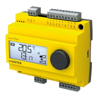
- Page 1 SAUTER flexotron®400 - RDT410 Manual P100012103...
-
Page 2: P100012103
Table of contents DISCLAIMER The information in this manual has been carefully checked and is believed to be correct. Fr. Sauter AG however, makes no warranties as regards the contents of this manual and users are requested to report errors, discrepancies or ambiguities to Fr. Sauter AG, so that corrections may be made in future editions. -
Page 3: Table Of Contents
SAUTER flexotron®400 - RDT410 Table of contents Table of contents Table of contents ..............................3 About the manual ............................4 Introduction to flexotron®400 ........................5 flexotron®400 controllers ........................5 Technical data .............................. 7 Installation and wiring ..........................9 Installation ............................9 Wiring .............................. -
Page 4: About The Manual
More information More information on RDT410 can be found in: RDT410 Guidelines for the technician flexotron®400 – Sales brochure RDT410 product data sheet The information is available for download from homepage http://www.sauter- controls.com/de. P100012103... -
Page 5: Introduction To Flexotron®400
SAUTER flexotron®400 - RDT410 Introduction to flexotron®400 Introduction to flexotron®400 flexotron®400 controllers The controller flexotron®400 is a range of pre-programmed, configurable controllers that can be set to handle everything from temperature control or humidity control to CO control or pressure control. - Page 6 SAUTER flexotron®400 - RDT410 Introduction to flexotron®400 In- and Outputs The RDT410 has 2 analogue inputs, Ni1000 1 analogue input for an external setpoint device, Ni1000 1 universal input, Ni1000 or digital 2 digital inputs ...
-
Page 7: Technical Data
SAUTER flexotron®400 - RDT410 Technical data Technical data Supply voltage ..........RDT410F301: 230 V AC; +10 / -15%; ..............RDT410F201: 24 V AC; ±15%. 50/60 Hz Power consumption ..................7.5 VA Running mode Climatic conditions according to IEC 721-3-3 ........Class 3k5 Ambient temperature ................ - Page 8 25°C (fixed) Accessories Temperature sensors ....Ni1000 sensors, for example:EGT330, EGT346 Setpoint device ..............Ni1000, EGT338F102 The accessories are available from Fr. Sauter AG. For more detailed information, see product sheets and instructions which are available at http://www.sauter- controls.com/en. P100012103...
-
Page 9: Installation And Wiring
SAUTER flexotron®400 - RDT410 Installation and wiring Installation and wiring Installation The RDT410 is intended to be installed and handled by professional personnel. The installation should conform to the requirements of installation category 3 and pollution degree 2. There are a number of mounting alternatives:... - Page 10 SAUTER flexotron®400 - RDT410 Installation and wiring Terminal Designation Operation 24 V~ RDT410F201 only 230 V~ RDT410F301 only Digital input Reference for DI1 and DI2 Digital input Reference for UI1 Digital input Reference for DI1 and DI2 Digital input Reference for UI1...
- Page 11 SAUTER flexotron®400 - RDT410 Installation and wiring 4.2.2 Inputs and outputs All ground terminals are interconnected and also connected to G0. Analogue inputs AI The analogue inputs must refer to an ground terminal. AI1 and AI2 are for Ni1000 temperature sensors only. AI1 has a temperature range of 0…84°C. AI2 has a temperature range of -30…+54°C.
- Page 12 SAUTER flexotron®400 - RDT410 Installation and wiring For more power an external transformer must be used. Wire the transformer according to the following figure. The two 500 mA fuses are important to prevent possible overloading of the triacs. P100012103...
-
Page 13: Control Modes
SAUTER flexotron®400 - RDT410 Control modes Control modes The RDT410 can be configured to any one of the following control modes. 1. Supply air temperature control. The supply air temperature is kept at the setpoint value by controlling the output signals on AO1 and AO2. - Page 14 SAUTER flexotron®400 - RDT410 Control modes For control mode 3, “Cascade connected room / extract air temperature control” you also need 2 sensors, “Supply air sensor” on AI1 and “Room sensor”, which are placed in the room or in the extract air on AI2.
- Page 15 SAUTER flexotron®400 - RDT410 Control modes External setpoint It is possible to use an external Ni1000 setpoint device. The setpoint device is connected between terminal 10 SPI and the reference for the analogue inputs, . For more information on configuration and setpoint reading, see chapters 7 and 10.
- Page 16 SAUTER flexotron®400 - RDT410 Control modes Shutdown mode (Only if frost protection sensor has been configured) Whenever the running mode switches to ”Off”, (normal shut-down or frost protection is activated) the controller will go into ”Shutdown mode”. The shutdown controller will control the output that is tied to the frost protection function to maintain a constant 25°C at the frost protection sensor.
- Page 17 SAUTER flexotron®400 - RDT410 Control modes Wiring examples See also chapter 4 Installation and wiring. A. RDT410 with electric heating and damper. Cascade control. B. RDT410 with water heating, 3-point- output. Supply air temperature control with outdoor compensation and external setpoint device.
- Page 18 SAUTER flexotron®400 - RDT410 Control modes 5.1.1 Control mode 4, Radiator circuit control with outdoor curve For this control mode you need two sensors, GT1 “Supply temperature” on AI1 and GT2 “Outdoor sensor” on AI2. You can also have a room temperature sensor on UI1 to let the room temperature offset give correction to the supply temperature.
- Page 19 SAUTER flexotron®400 - RDT410 Control modes To indicate that room control is activated the display symbol showing a thermometer outside the house is replaced by a thermometer inside the house. External setpoint It is possible to set the room setpoint via an external Ni1000 setpoint device. The...
- Page 20 SAUTER flexotron®400 - RDT410 Control modes 5.1.2 Control mode 5 Domestic hot water control For this control mode you need a single sensor, “Supply water temperature” on Periodic overheating To reduce the risk of Legionella bacteria growth a periodic overheating of the water can be configured.
-
Page 21: Display And Encoder
SAUTER flexotron®400 - RDT410 Display and encoder Display and encoder All setting and configuration is done using the display and encoder. The menu information on the display is organised in a tree fashion. Using the encoder you can move between menus, set values etc. -
Page 22: The 3 Second Level
SAUTER flexotron®400 - RDT410 Display and encoder acknowledged. There is one menu display for each alarm with symbols showing which type of alarm it is. See chapter 8 Alarm handling. Calculated setpoint For control modes with outdoor temperature compensation or cascade control, the controller does not work towards a fixed setpoint value. -
Page 23: Setpoint
SAUTER flexotron®400 - RDT410 Setpoint Setpoint The setpoint menu is normally accessed from the base display by a clicking on the encoder knob. If you wish to change the displayed value, click on the knob again and the change indicators will start to flash to show that you are now in change mode. -
Page 24: Alarm Handling
SAUTER flexotron®400 - RDT410 Alarm handling Alarm handling If there are any active, unacknowledged alarms, the alarm indicator in the Base Display will light up and start flashing. If DO1 is configured as alarm output, it will be activated. The alarm handling menus are accessed from the Base Display by a click on the encoder knob. -
Page 25: Clock And Scheduler
SAUTER flexotron®400 - RDT410 Clock and scheduler Clock and scheduler The menus for setting the clock and the scheduler times lie in the 3-seconds level. This level is accessed from the basic level by clicking and holding the encoder knob for 3 seconds. - Page 26 SAUTER flexotron®400 - RDT410 Clock and scheduler If you want the unit to run around the clock, set the on-time to 0:00 and the off- time to 0:00. Menu 0.9, Override After the eight switching point menus there is a ninth, 0.9. There the present output status of the scheduler is shown and you can manually override the setting.
- Page 27 SAUTER flexotron®400 - RDT410 Clock and scheduler Should you want the comfort period on Friday to run on until 23:30 you can set the fourth on-time to day 5 and 23:30 and the fourth off-time to day 5 and 21:01.
-
Page 28: Configuration
SAUTER flexotron®400 - RDT410 Configuration 10 Configuration All the configuration menus lie in the 10-seconds level. This level is accessed from the Base Display by clicking and holding the encoder knob for 10 seconds. There are numerous configuration menus covering all available options and combinations. - Page 29 SAUTER flexotron®400 - RDT410 Configuration Output Graphic symbol symbol 1. Heating 2. Cooling 3. Heating Cooling 4. Heating Heating 5. Cooling Cooling 6. Heating Damper 7. Cooling Damper In alternative 4, Heating-Heating AO2 will be activated first on increasing heat demand.
- Page 30 SAUTER flexotron®400 - RDT410 Configuration Menus X.4 P-band Here you set the P-band (Proportional band). The P-band is the control offset necessary to drive an output signal from 0 to 100%. In configurations involving two outputs the same P-band applies to both outputs.
- Page 31 SAUTER flexotron®400 - RDT410 Configuration 0°C temperature boost In control mode 4 an extra temperature boost can be added at 0°C outdoor temperature. The boost recedes from the set value to 0 over ±3 degrees. Supply temp Outdoor temp D-factor Control mode 5, Domestic hot water temperature control is often a very difficult application which calls for responsive control.
- Page 32 SAUTER flexotron®400 - RDT410 Configuration Pump exercise If the pump stands still for prolonged periods during the summer there is the risk of the pump impeller seizing. To reduce this risk the flexotron®400 has a pump exercise function which will start and run the pump for 5 minutes at 15:00 each day.
- Page 33 SAUTER flexotron®400 - RDT410 Configuration Menus X.9 Maximum compensation, CMP (Control mode 2) Supply air max limit (Control mode 3) High temperature setpoint (Control mode 4) For control mode 2. The maximum setpoint compensation value. Compensation will start to be added to the setpoint value when the outdoor temperature falls below the start point S.P entered in menu 2.8.
-
Page 34: Storage Of Settings
SAUTER flexotron®400 - RDT410 Configuration Menu OK Last of the configuration level menus is the OK-menu. To leave the configuration level, go to this menu and klick on the encoder knob. On exit from the configuration level you will not be returned to the Basic level but to the Time and Scheduler level. -
Page 35: Index
SAUTER flexotron®400 - RDT410 Index Index Analogue outputs ......... 11 Digital inputs ..........11 Universal inputs ........... 11 Installation ............9 10-second level ......... 22, 28 LVD..............7 3-second level ........... 22, 25 Menu Analogue inputs ..........11 Configuration ..........28 Analogue outputs ..........11 I/O ............ - Page 36 SAUTER flexotron®400 - RDT410 Index Control mode 4 ..........19 Control mode 5 ..........20 Wiring ..............9 general ............10 Wiring diagram Printed in Switzerland © Fr. Sauter AG Im Surinam 55 CH-4016 Basel Tel. +41 61 - 695 55 55 Fax +41 61 - 695 55 10 www.sauter-controls.com...
Need help?
Do you have a question about the SAUTER flexotron 400 and is the answer not in the manual?
Questions and answers