Advertisement
Quick Links
Advertisement

Related Manuals for sauter equitherm M60


Summary of Contents for sauter equitherm M60
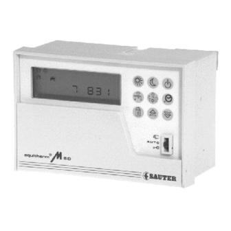
- Page 1 Operating instructions Heating controller QRK 201 F001 7 000458 003 H2 7 000458 003...
- Page 2 You have opted for a Sauter control unit, a quality product from a leading manufacturer of control devices for heating, ventilation and air conditioning. Your new device features simple operation in connection with advanced micro-processor technology. Please follow operating instructions for adapting the device to your specific system and requirements.
- Page 3 – – Table of contents User information ..................3 Controller front view .
- Page 4 – – Calibration of the temperature and flow inputs ............30 –...
- Page 5 – – User information Controller front view Information panel Operating keys SERV Slide switch AUTO B01493 Service and adaptor keypad Interface RS 232 Operating elements User keypad with function keys Service and adjustment keypad Normal operation Numerical keypad . . . Reduced operation Clearing and preparation of a new entry OFF mode...
- Page 6 – – The information centre (LCD) Heating Domestic hot water m /h °C SERV B01494 This display unit provides information on the current operating status of the heating system. Flashing symbols prompt parameter . . . entry or indicate a special operating condition and are designated with the symbol in the following text.
- Page 7 – – Special conditions External temperature below freezing (frost-protection function will be activated as required) Optimised heating phase Optimised temperature reduction/switch-off phase Flow or return-temperature limiting function has been triggered Emergency operation: flow transmitter defective Outputs Time-channel contact to exterior is open (will Valve 1 opens only be displayed for creating the corresponding time program)
- Page 8 – – Control values In closed-loop operation, several values can be inquired or dis- A thermometer symbol is always shown in conjunction with a played continuously. temperature setpoint; a flashing thermometer symbol indicates an actual temperature value. The display can be changed by means of the incrementation keys (forward) and (return).
- Page 9 – – Actual flow temperature Flow temperature setpoint regulated by valve V1 Actual return temperature Return temperature limitation setpoint Actual flow temperature Flow temperature setpoint regulated by valve V2 Flow temperature setpoint regulated by valve V2 Actual return temperature Return temperature limitation setpoint Primary flow rate, actual value m /h flow rate...
- Page 10 – – Frequently used abbreviations Temperatures = outdoor temperature = room-temperature setpoint = flow temperature = return temperature = flow-temperature setpoint = return-temperature setpoint = flow-temperature setpoint during domestic-hot-water = domestic-hot-water temperature FS(W) charge = setpoint of domestic-hot-water temperature = base point (initial point) of the heating curve = room temperature Control parameters = slope of heating characteristic...
- Page 11 – – Factory setting The factory settings ( ) refer to an average building and a common system layout. You can, of course, adpat all settings quickly and easily to your specific requirements. Day of the week and time SET Date for switching from wintertime to summertime 12.03 Wednesday 12:03;...
- Page 12 – – Setting year and date Display Explanation S E T e. g. 1 23:45 SET mode selected, display shows day of the week and time e. g. 93 10.18 Select controller date (year/month/day) – – –:– – Invalid date cleared e.
- Page 13 – – Selecting the operating mode (heating and domestic hot water) By pressing one of the keys shown below, you can select the following modes of operation: Automatic mode: Heating operation and enabling/disabling the charge of domestic water is controlled according to the time program as specified in PRO 0...2.
- Page 14 – – Short interruption of the weekly heating program When operation is controlled by the weekly program, the operating mode can be changed until the next switching com- mand is released. The operating modes are switched according to the symbols printed on the keys. If a second heating circuit is installed, the operator must specify whether the entry is valid for heating circuit 1 or heating circuit 2...
- Page 15 – – Adapting the heating characteristic A properly adapted heating characteristic results in a constant typical for the entire building, the heating characteristic can be room temperature even with varying outdoor temperatures. The adapted manually (see below for automatic correction). If the factory settings of the controller heating characteristic are de- set normal temperature (user adjustment value PAR no.
- Page 16 – – Adapting the normal-temperature setpoint B01532 Normal temperature can easily be changed by pressing the keys shown above (see also PAR 1 and 7). If a second heating circuit is installed, the operator must specify whether the entry is valid for heating circuit 1 or heating circuit 2 after pressing the yellow key.
- Page 17 – – PRO time programs Dependent on the corresponding system configuration, the com- programs PRO 0...2, several components of the system can be ponents of the system can be controlled individually. By pressing triggered once (timer) or repeatedly (weekly and annual pro- one of the yellow keys of the user keypad, the controller is grams).
- Page 18 – – If two heating circuits are installed and if both circuit 1 and circuit Annual program, weekly program, timer, external clock, conti- 2 are supplied by the same heat exchanger (SERV 01 = +3), nuous operating mode, etc., have the following priorities: heating circuit 1 always has priority * .
- Page 19 – – Timer PRO 0 Enables the operating status or mode to be specified for 1...999 hours (~ 40 days). Function Display P R O Set controller to time-program entry status – P R O Select timer function Select time channel to be programmed: Heating circuit 2 (see above) e.
- Page 20 – – Weekly program PRO 1 Up to 40 switching commands in total can be entered for the existing time channels with time periods of up to one week. The program is repeated every week. Function Display P R O Set controller to time-program entry status –...
- Page 21 – – Annual program PRO 2 Up to 28 switching commands in total, each consisting of month, Each time period is defined by its beginning and its end. day of the month and operating mode, can be entered for the existing time channels with time periods within a duration of 12 months.
- Page 22 – – Inquiry and adaptation of user adjustment values PAR (parameters) Function Call the first user adjustment value Inquire the next adjustment value (page forward) Inquire the next adjustment value (page backward) Clear the value shown on the display (if required) Enter valid value Return to the desired operating mode by pressing the corresponding key or with automatic return to the last mode after approx.
- Page 23 – – [°C] [°C] B01534 Family of heating characteristic for T = 20 °C and a curvature factor (SERV 66) = 0.5. Example for factory setting: an outdoor temperature of T = –5 °C results in a flow temperature of T = 58 °C.
- Page 24 – – If the controller is configured for 2 heating circuits, the following additional PAR user adjustment values are available. Setting value Function 20.0 ° C Room temperature setpoint for heating circuit 2 during normal operation ( ) (5.0...39.9 ° C) 12.0 °...
- Page 25 *) After a mains power failure during manual operation, the control elements will again be driven to this limit value. Automatic switch-off/switch-on • With its automatic switch-off mode, your Equitherm M60 heating If the outdoor temperature exceeds the value of the controller saves energy whenever possible.
- Page 26 – – Manual activation of winter mode After the automatic heating limit (PAR 4) has been detected, the Winter operating can also be activated at any time by pressing controller will switch to summer mode (heating OFF ) after a de- and then in sequence (refer also to the section "Se- lay (PAR 6).
- Page 27 – – Accessories The following accessories enable the functions provided by the controller to be exploited to full advantage. Room-temperature sensor EGT 320 Remote-control unit EGS 52/15 Required for the implementation of the following functions: This unit can be connected with or without built-in room-tempe- rature sensor.
- Page 28 – – Specialist’s information Inquiry and adjustment of SERV service settings Service settings are closely related to the safety of the heating to its position. The values can also be inquired in "AUTO" system and may only be adjusted by trained specialists. For position.
- Page 29 – – Output configuration, running times of valve actuators, follow-up period of pumps Status configuration of 2-point outputs in manual operation SERV setting value Function The status of the 2-point outputs (ON and OFF) in manual operation is determined by specifying a numerical value (0...15).
- Page 30 – – 3-point output configuration SERV setting value Function Configuration of final control elements according to the type of heating system. Valve V1 always controls only one circuit, whereas valve V2 can control one or two heating circuits and/or a domestic-hot-water circuit.
- Page 31 – – 2-point output configuration The two-point outputs (terminals 7, 6, 4, 3) can be configured according to the following table (setting values SERV 04...07). –1 No function (output is not used) Time channel to exterior. ON (= 1) and OFF (= 0) commands can be entered in the time programs.
- Page 32 Input alignment Temperature Sauter nickel temperature sensors guarantee precise temperature measurements. However, line resistance compensation may be required if the connecting cables are particularly long. The following temperature measurement inputs (Ni 1000 Ω at 0 ° C) can be calibrated within a range of ± 9.9 ° C.
- Page 33 – – Examples for the calibration of outdoor temperature sensors Assumption: The controller is configured with the outdoor temperature sensor being connected at terminal 23 (input I Example 1 Example 2 Initial situation: Initial situation: Temperature measured by thermometer + 9.5 ° C Temperature measured by thermometer + 1.5 °...
- Page 34 – – Flow rate SERV setting value Function Calibration of current signal input from flow meter, terminal 32. (–0.99...+0.99) (mA) Example for the calibration of the current signal for flow-rate measurement A current signal of 20 mA shall correspond to a flow rate of 10.0 m /h;...
- Page 35 – – Input configuration Binary inputs SERV setting value Function Influence of an external time switch on the operating mode. In operation controlled by a time program, the current operating mode can be overwritten via a closed –1 external (gold) contact. When the contact is opened again, the operating mode is again determined by the time program of the controller (please refer also to PRO time programs).
- Page 36 – – Temperature sensor inputs R e m ote control for hea ting circuit 2 w ith out ro om -tem peratu re contro ller*) R e m ote control for hea ting circuit 1 w ith out ro om -tem peratu re contro ller*) R e m ote control for heating circuit 2 w ith...
- Page 37 – – Temperature sensor input (continued) 8 controller inputs (I ...I corresponding to SERV 20...SERV 27) can be configured according to the following table. –01 without function (input is not used) Input for outdoor temperature sensor T Input for room temperature sensor T (or room temperature signal from terminal 0 of remote control EGS 52/15) acting on heating circuit 1 (connect terminal 3 of EGS 52/15 to earth).
- Page 38 – – Inputs for flow-rate measurement SERV setting value Function –1 Configuration of the controller for measuring the primary flow rate. flow rate –1 not measured by the controller measured via auxiliary contact(s) measured by means of counting pulses in the unit litres/pulse measured by means of counting pulses in the unit pulses/litre measured by means of a DC signal 0...20 mA measured by means of a DC signal 4...20 mA...
- Page 39 – – Return-temperature limitation SERV setting value Function Upper limit value of return temperature (0...149) (°C) Lower limit value of return temperature (0...149) (°C) Outdoor temperature at which the floating part of return temperature limitation begins (–49...+49) (°C) Slope of floating part of the limitation characteristic for return temperature (0...4.9) Limit value of return temperature (absolute value in °C) during domestic-hot-water charging.
- Page 40 – – Closed-loop control with final control element V1 SERV setting value Function Proportional band X of PI-control with final control element V1 (10...99) (K) Reset time t of PI-control with final control element V1 (15...999) (s) Neutral zone X of PI control with V1 If the actual flow temperature value lies within a range of the flow temperature setpoint ±...
- Page 41 – – Closed-loop control via final control element V2 SERV setting value Function Proportional band X of PI-control with final control element V2 (10...99) (K) Reset time t of PI-control with final control element V2 (15...999) (s) Neutral zone X of PI-control with V2 If the actual flow temperature value lies within a range of the flow temperature setpoint ±...
- Page 42 – – Heating system, building and air conditioning General setting values Heating (degree) days Any day is regarded as a heating day if the outdoor temperature The number of heating degree days is calculated by adding up averaged over a period of 24 h falls below the corresponding the difference of outdoor temperature (sensor measuring value) heating limit (SERV 61).
- Page 43 – – Heating characteristic 1 (for heating circuit 1) SERV setting value Function 0.50 Curvature factor of the heating characteristic for heating circuit 1 The curvature factor takes account of the heat-dissipating properties of the heating system. Particularly for higher outdoor temperatures (typically 10...20 ° C), the secondary flow temperature can be modified efficiently with this parameter if required.
- Page 44 – – Heating characteristic 2 (for heating circuit 2) SERV setting value Function 0.50 Curvature factor of the heating characteristic for heating circuit 2 The curvature factor takes account of the heat dissipating properties of the heating system. Particularly for higher outdoor temperatures (typically 10...20 ° C), the secondary flow temperature can be modified efficiently with this parameter if required.
- Page 45 – – Limits for heating characteristic 2 (heating circuit 2) SERV setting value Function Max. limitation of flow-temperature setpoint for heating circuit 2 (max. limitation of the secondary flow temperature is ignored during a charge of domestic hot water in systems with one heat exchanger and no secondary mixing valve.) (20...149) (°...
- Page 46 – – Switching-time optimisation The controller can optimise the times for switching on/off with provided by a room-temperature sensor in the reference room regard to heating circuit 1. When optimisation mode is selected, of heating circuit 1 is normally required; (if the signal is supplied the controller calculates the latest possible switch-on time and by the remote-control unit EGS 52/15, we recommend that this the earliest possible switching-off time based on the current...
- Page 47 – – SERV setting value Function Optimised switch-on of the heating system (heating circuit 1) This setting value enables the optimised switch-on of the heating system and simultaneously limits the max. permissible warm-up time. 0,0 h Optimised switch-on is disabled. The switching times of the time programs are relevant for operation.
- Page 48 – – Adaption of the heating characteristic(s) The heating characteristic of heating circuit 1 (and heating Whether an automatic adaptation is implemented and which of circuit 2, if installed) can be automatically adapted to the building the three dimensions is adjusted automatically depends prima- properties and heating system.
- Page 49 – – SERV setting value Function –1 Adaption of heating characteristic 2 (heating circuit 2) –1 Adaption disabled Adaption enabled, all 3 values are initially adjusted with the highest possible influence Adaption enabled, all 3 values are from the beginning adjusted with the lowest possibile influence Counter for number of adaptions steps "extraneous heat"...
- Page 50 – – SERV setting value Function Dependent on the external temperature, the controller determines whether domestic-hot-water heating has priority or is handled in parallel to heating circuit 1. Domestic-hot-water heating has priority if the external temperature lies above this setting value (depending on the configuration of the system, it may be possible that the flow temperature of the heating-system water reaches a value corresponding to SERV 91 or SERV 93;...
- Page 51 – – Characteristic curve for the control Characteristic curve for the control of heating circuit 2 of heating circuit 1 Heating Heating Outdoor temperature Outdoor temperature B01747 B01696 Characteristic curve for the control of domestic hot water Domestic hot water FS (WS2) FS (WS1) B01697...
- Page 52 – – Resistance values of the temperature sensors (Ni1000) Temperature [° C] Resistance value [Ω] 1549 1483 1417 1353 1291 1230 1171 1112 1056 1000 −10 −20 –30 –40 Wiring diagram Flow measurement All contacts suppressed with RC module 24V~ 230 V~ I0...I7 = configurable sensor input...
- Page 53 – – Record sheets Weekly programs for time channels (a max. total of 40 switching commands, refer to section PRO 1) daily Tuesday Thursday Saturday Monday Wednesday 5 Friday Sunday Weekly program Heating circuit 1 Weekly program Heating circuit 1 Switching time Operating mode Switching time...
- Page 54 – – Weekly program Time channel to exterior Weekly program Domestic-hot-water circulation Switching time Operating mode Switching time Operating mode Daily Daily Special day Special day Special day Special day B02643 Special day Special day (Without switching command: continuously ON) (Without switching command: continuously ON) 7 000458 003...
- Page 55 – – Annual programs for time channels (a max total of 28 switching commands, refer to section PRO 2) Annual program Heating circuit 1 Date (month – day) Operating mode Annual program Domestic hot water Date (month – day) Operating mode Annual program Heating circuit 2...
- Page 56 – – Configuration sheet (refer to section PAR and SERV) PAR.. System value Meaning 20.0 (° C) 12.0 (° C) Heating limit (° C) Heating limit (° C) Delay time (h) 20.0 (° C) 12.0 (° C) SERV.. Manual operation Basic type of installation Running time V1 (s) Running time V2 (s)
- Page 57 – – Configuration sheet (continued) SERV.. System value Meaning –1 Function output I –1 Function output I Function output I Function output I –1 Function output I Function output I –1 Function output I Function output I –1 Flow rate configuration 1.00 Value of counting pulse 10.00...
- Page 58 – – Configuration sheet (continued) SERV.. System value Meaning Xp V2 (PI, K) Reset time V2 (PI, s) V2 (PI, K) +2.0 Degree of intervention for return-temperature limitation at V2 (K/K) Degree of intervention for flow-rate limitation at V2 (K/min) Valve closed delay time for V2 (min) 0.20 Minimum opening after delay V2...
- Page 59 – – Configuration sheet (continued) SERV.. System value Meaning Wall component Building-cooling time constant (h) 0.70 Comfort factor Super-heating value (K) Optimised start-up of HK 1 (h) Optimised switch-off of HK 1 (h) Control of UP 1 (h) –1 Adaption of building-cooling time constant –1 Adaption of heating characteristic 1 –1...
- Page 60 – – Index Abbreviations ............... . . 8 Accessories .
- Page 61 – – Danger of scalding ..............47 Date .
- Page 62 – – Heating limit "OFF" winter-summer ............21 Heating limit "ON"...
- Page 63 – – Permissible warm-up time ............. . . 45 Pre-control .
- Page 64 Year................6, 9 Printed in Switzerland Right of amendment reserved N.B.: A comma between cardinal numbers denotes a decimal point Fr. Sauter S.A., CH-4016 Basle 7 000458 003 H2...
Need help?
Do you have a question about the equitherm M60 and is the answer not in the manual?
Questions and answers