Table of Contents
Advertisement
Quick Links
SAUTER equitherm
®
Electronic heating controller
Contents:
1. General
2. Indicators and operating controls
1
General
Congratulations! You have chosen a Sauter controller – a quality
product from one of the leading manufacturers of control products
for the HVAC industry. Your heating controller combines simplicity of
operation with ultra-modern microprocessor technology. Follow these
operating instructions so that you can adapt the device to your needs.
1.1
Key
Factory setting
BW
Domestic water
CP
Communication parameters
HK
Heating circuit
Imp
Impulse
KW
Chilled water
LP
Charge pump
prim.
Primary side
SP
SERVice parameters
Flashing value in display denotes:
•
special/unusual status
•
value that can be changed
2
Indicators and operating controls
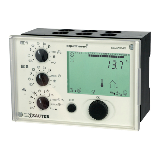
2.1
Front view of EQJW245
1
PROG
1
1
2
2
PROG
LOG
PROG
PROG
1x
1
Rotary switch
2
Display
3
4
ESC key
2.2
LCD
0 1 2 3 4 5 6 7 8.... ......2 1 22 23 24
Times for normal mode on the current day
Time, date, setpoints, actual values etc.
Automatic mode according to weekly and calendar
switching programme. Flashing: limited/unlimited
temperature change
Controller operating in normal mode
Controller operating in reduced mode
Controller operating in standby mode.
Flashing: frost protection is active
Sensor is faulty
Heating pump for HC1, HC2 is switched on
Control unit 1, 2 is opened ( ) or closed ( )
,
Setpoint temperature.
Flashing: actual temperature is displayed
www.sauter-controls.com
sek.
Secondary side
T
Outside temperature
A
T
Boiler temperature
B
T
Flow temperature
F
T
Room temperature
R
T
Return temperature
RF
T
Temperature of
W
domestic water
UP
Heating pump
equitherm
EQJW245
®
2
0 1 2 3 4 5 6 7 8 9 10 11 12 13 14 15 16 17 18 19 20 21 22 23 24
°C
h
sec
STOP
1
1
OK
ESC
en Quick reference
Flow temperature
Outside temperature
Room temperature
Return temperature
Charge temperature of domestic water
Domestic-water temperature 1
Domestic-water temperature 2
Display refers to HC1 (–) or HC2 (=)
,
Controller is in summer mode
Calendar Switching Programme is currently active
Domestic water.
Flashing: increased temperature
Charge pump is switched on
An error has occurred
2.3
Rotary switch for heating circuit 1 (top)
Operating modes
Automatic mode as per
switching programme
2
Controller is continuously in
normal mode
Controller is continuously in
reduced mode
Controller is continuously in
standby mode
3
Access to manual mode for
heating
4
2.4
Rotary switch for heating circuit 2 (middle)
Operating modes
Automatic mode as per
switching programme
Controller is continuously in
normal mode
Controller is continuously in
reduced mode
Controller is continuously in
standby mode
Access to manual mode for
heating
1
Normal mode corresponds to nominal mode as per EN12098-1
2
Standby mode means that the heating is switched off and the anti-
frost function is active.
Inputs
Setpoint adjustment,
normal mode
Setpoint adjustment,
reduced mode
Enter weekly and calendar
programme for heating
(Un)limited temperature
change
Access to SERVice,
commissioning and
communication level
Inputs
Setpoint adjustment, normal
mode
Setpoint adjustment,
1
reduced mode
Enter weekly and calendar
programme for heating
(Un)limited temperature
2
change
Access to logbook
EQJW245
1/6
Advertisement
Table of Contents

Related Manuals for sauter equitherm EQJW245


Summary of Contents for sauter equitherm EQJW245
- Page 1 4. How to operate (user) General Flow temperature Congratulations! You have chosen a Sauter controller – a quality Outside temperature product from one of the leading manufacturers of control products for the HVAC industry. Your heating controller combines simplicity of Room temperature operation with ultra-modern microprocessor technology.
- Page 2 Set rotary switch to Turn input knob to set date Press input knob to confi rm new date Turn input knob until ‚In‘ appears The middle and bottom rotary switches should be set at one of the positions for an operating mode. www.sauter-controls.com...
- Page 3 8 = two regulating valves (1 primary for HC, 1 for direct DW SP48 25.10 Summertime/wintertime change-over charge w/o mixing control) Wintertime/summertime change-over P55 = P56 denotes For details, see ‹Application› sheet. SP49 25.03 no change-over Optimisation for HC1 SP50 0 = not enabled; 1 = enabled www.sauter-controls.com...
- Page 4 Note: one controller in the grouping must always be given the address ‚1‘ CP05 – MOD bus via RS485: address for EQJW 245 MOD bus via modem: telephone number of the control CP06 – station CP07 – SMS via modem: telephone number of the provider www.sauter-controls.com...
- Page 5 , use the ESC key or set the rotary switch to command is changed another position. Press the input knob; time for the switching 06:40 command is confi rmed 06:40 Turn input knob; select operating mode for the switching command 06:40 Press input knob; operating mode is confi rmed www.sauter-controls.com...
- Page 6 An empty switching command is shown as ‹_ _ _ _› 4.11.3 Enter switching commands © Fr. Sauter AG Turn the input knob until the next empty Im Surinam 55 switching command appears. CH-4016 Basel Tel. +41 61 - 695 55 55 Press the input knob;...
Need help?
Do you have a question about the equitherm EQJW245 and is the answer not in the manual?
Questions and answers