Table of Contents
Advertisement
Quick Links
Advertisement
Table of Contents

Related Manuals for sauter flexotron 800 Series


Summary of Contents for sauter flexotron 800 Series
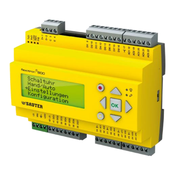
- Page 1 Sauter flexotron®800 ventilation Manual P100012082 Manual...
- Page 2 Table of contents DISCLAIMER The information in this manual has been carefully checked and is believed to be correct. Fr. Sauter AG however, makes no warranties as regards the contents of this manual and users are requested to report errors, discrepancies or ambiguities to Fr.
-
Page 3: Table Of Contents
Sauter flexotron®800 ventilation Table of contents Table of contents Table of contents ..............................3 About the manual ............................7 About flexotron® 800 ........................... 8 Application choice ..........................8 Select language ..........................9 Ventilation application ........................9 flexotron®800 hardware overview....................11 flexotron®800 model overview ...................... - Page 4 Sauter flexotron®800 ventilation Table of contents Start conditions ..........................54 Stop conditions ..........................54 Start sequence ..........................54 Stop sequence ..........................55 Display, LEDs and buttons ........................56 Display .............................. 56 LEDs ..............................56 Buttons ............................. 56 Navigating the menus........................56 Access rights ..............................
- Page 5 Sauter flexotron®800 ventilation Table of contents 15.6 Alarm settings ........................... 75 15.7 Save and restore settings ........................ 78 16 Configuration .............................. 79 16.1 Inputs and outputs ..........................79 16.2 Control function ..........................82 16.3 Fan control ............................82 16.4 Extra control circuit ........................... 83 16.5...
- Page 6 Sauter flexotron®800 ventilation Table of contents 18.1 Alarm handling ..........................110 18.2 Free text ............................110 18.3 Revision number ..........................110 18.4 Language ............................110 18.5 Indication LEDs ..........................111 18.6 Changing the battery ........................112 18.7 Start-up wizard ..........................113 18.8...
-
Page 7: About The Manual
More information More information about flexotron®800 can be found in: Manual SAUTER-CASE-flexotron® -- - Manual of how to configure the controllers using the PC software SAUTER CASE flexotron® Network variables Modbus -- - Variable list for Modbus communication ... -
Page 8: About Flexotron®800
Sauter flexotron®800 ventilation About flexotron®800 About flexotron®800 flexotron®800 series comprises three model sizes: 8, 15 or 28 in-/outputs. In each model of flexotron®800, all applications are loaded in a separate memory area. All configuration and normal handling can be done using the display and buttons or using the configuration tool CASE flexotron®, installed on a PC and connected via a... -
Page 9: Select Language
Sauter flexotron®800 ventilation About flexotron®800 Select language In the basic display, press the Right button three times to go to the language selection. Choose language English Press OK to choose language. Use the up and down arrows to move between languages and press OK to confirm your choice. - Page 10 Sauter flexotron®800 ventilation About flexotron®800 Support control When using the control function room control or extract air temperature control, it is possible to utilise support-heating and/or support-cooling. Minimum running time is settable 0…720 minutes. (factory setting 20 minutes). Free cooling The function is used during the summer to cool the building during the night using cool outdoor air thereby reducing the need to run chillers during the day.
-
Page 11: Flexotron®800 Hardware Overview
Sauter flexotron®800 ventilation About flexotron®800 flexotron®800 hardware overview Model RDT808 RDT815 RDT815 RDT815 RDT828 RDT828 RDT828 F211 F011 F211 F221 F011 F211 F211 Analogue Inputs Digital Inputs Universal Inputs Analogue Outputs Digital Outputs RS485* WEB (TCP/IP) Display Ext. display Option Option *Communication port RS485 is not available for variants with WEB (TCP/IP). -
Page 12: Technical Data
Sauter flexotron®800 ventilation About flexotron®800 Technical data ..............Protection class IP20, when fitted ........Display 4 rows of 20 characters. Background illumination LEDs ................Yellow Settable parameter ..................Alarm indication ..........Clock Year base 24 hour clock with battery backup. - Page 13 Sauter flexotron®800 ventilation About flexotron®800 Outputs ........ Configurable 0…10 V DC; 2…10 V DC; Analogue outputs AO 10…0 V DC or 10…2 V DC, 2 mA 8 bit D/A short-circuit protected ......Digital outputs DO Mosfet outputs, 24 V AC/DC, 2 A continuous not short-circuit protected, totally max 8 A.
-
Page 14: Installation And Wiring
Sauter flexotron®800 ventilation Installation and wiring Installation and wiring Installation The controller flexotron®800 can be mounted in a DIN-standard casing (minimum 9 modules), on a DIN-rail in a cabinet or, using a suitable front-mounting kit, in a cabinet door or other control panel. -
Page 15: Wiring
Sauter flexotron®800 ventilation Installation and wiring Wiring At the end of this section are terminal assignment plans that show the available factory setting configurations. There are also empty wiring diagrams. Since the function of most of the inputs and outputs depends on the programming of the unit the final wiring diagram cannot be filled in until the installer has decided how to use the inputs/outputs. - Page 16 Sauter flexotron®800 ventilation Installation and wiring Analogue outputs Analogue outputs must refer to the Masse- terminal placed in the AO terminal block. All analogue outputs can be individually set to any one of the following signals: 0…10 V DC 2…10 V DC 10…0 V DC...
- Page 17 Sauter flexotron®800 ventilation Installation and wiring 24 V ~ supply and 24 V = relays 24 V = supply and 24 V ~ relays 3.3.2 Input and outputlists The lists below are intended to be used during commissioning to help you keep track of the desired input and output functions.
- Page 18 Sauter flexotron®800 ventilation Installation and wiring Description CASE flexotron® Display sensor, 0…10 V DC CO2 Sensor Pressure transmitter supply air, SAF Pressure SAF pressure 0…10 V DC Pressure transmitter extract air, EAF Pressure EAF pressure 0…10 V DC De-icing sensor, heat exchanger...
- Page 19 Sauter flexotron®800 ventilation Installation and wiring Description CASE flexotron® Display Fire damper end-switch monitoring Fire Damper Indication Fire damper- Extended operation, Normal Extended Operation, Ext run 1/1 Normal Extended operation, Reduced Extended Operation, Ext run 1/2 Reduced External switch...
- Page 20 Sauter flexotron®800 ventilation Installation and wiring Digital output signal Description CASE flexotron® Display Start/stop Supply air fan Normal SAF Start 1/1 Normal SAF 1/1- Speed speed Start/stop Extract air fan Normal EAF Start 1/1 Normal EAF 1/1- Speed speed...
- Page 21 Sauter flexotron®800 ventilation Installation and wiring Description CASE flexotron® Display Step controller cooling, step 1 Cool Step 1 Cool step1 Step controller cooling, step 2 Cool Step 2 Cool step2 Step controller cooling, step 3 Cool Step 3 Cool step3...
-
Page 22: Wiring Diagram Rdt828
Sauter flexotron®800 ventilation Installation and wiring Wiring diagram RDT828 (Configuration 828 Cascade & CO (See also picture of the position of the terminals on page 14) Power supply 24 V AC ±15%. 50/60 Hz, or 24 V DC RS485 Modbus (not with... -
Page 23: Wiring Diagram Rdt828
Sauter flexotron®800 ventilation Installation and wiring Wiring diagram RDT828 (Configuration 828 cascade & humidity) (See also: Figure for terminal assignment, page 14) Power supply 24 V AC ±15%. 50/60 Hz or 24 V DC RS485 Modbus (not with Earth conductor... -
Page 24: Wiring Diagram Rdt815
Sauter flexotron®800 ventilation Installation and wiring Wiring diagram RDT815 (Configuration 815 cascade control) (See also: Figure for terminal assignment, page 14) Power supply 24 V AC ±15%. 50/60 Hz or 24 V DC RS485 Modbus (not with Earth conductor web (TCP/IP) models) +24 V +24 V DC. -
Page 25: Wiring Diagram Rdt815
Sauter flexotron®800 ventilation Installation and wiring Wiring diagram RDT815 (Configuration 815 fixed-value) (See also: Figure for terminal assignment, page 14) Supply voltage 24 V AC ±15%. 50/60 Hz or 24 V DC RS485 Modbus (not with web (TCP/IP) models) Earth conductor +24 V +24 V DC. -
Page 26: Wiring Diagram Rdt808
Sauter flexotron®800 ventilation Installation and wiring Wiring diagram RDT808 (Configuration 808 fixed-value) (See also: Figure for terminal assignment, page 14) Power supply 24 V AC ±15%. 50/60 Hz or 24 V DC RS485 Modbus (not with web (TCP/IP) models) Earth conductor +24 V +24 V DC. -
Page 27: Empty Wiring Diagram Rdt828
Sauter flexotron®800 ventilation Installation and wiring Empty wiring diagram RDT828 Power supply 24 V AC or 24 V DC, ±15%. 50/60 Hz RS485 Modbus (not with web (TCP/IP) models) Earth conductor +24 V +24 V DC. Reference point for digital inputs DI... -
Page 28: Empty Wiring Diagram Rdt815
Sauter flexotron®800 ventilation Installation and wiring 3.10 Empty wiring diagram RDT815 Power supply 24 V AC or 24 V DC, ±15%. 50/60 Hz RS485 Modbus (not with web (TCP/IP) models) Earth conductor +24 V +24 V DC. Reference point for digital inputs DI... -
Page 29: Commissioning
Sauter flexotron®800 ventilation Commissioning Commissioning General Before the controller flexotron®800 can be used it must be configured, inputs and outputs must be assigned and all relevant parameters must be set. All commissioning can be done using the flexotron®800 front panel display and buttons or using the display unit RDB800. - Page 30 Sauter flexotron®800 ventilation Commissioning At the end of each function description there is a table of the necessary inputs and outputs to implement the function. At the end of the manual there is a list of all the analogue and digital inputs and outputs. As you read, mark in the list the inputs and outputs you will be using for the application you are building.
-
Page 31: Functional Description
Sauter flexotron®800 ventilation Functional description Functional description Temperature control General The controller flexotron®800 has a choice of the following control modes: 1. Supply air control 2. Outdoor temperature compensated supply air control 3. Cascaded room temperature control 4. Cascade connected extract air temperature control 5. - Page 32 Sauter flexotron®800 ventilation Functional description Output signal 100% Cooling Heat Heating Controller exch. signal 100% Heat demand In addition to these three, it is possible to connect another anologue output signal to control an optional sequence, Y4 Extra sequence. "Y4 Extra sequence" is set in the same way as above.
- Page 33 Sauter flexotron®800 ventilation Functional description Heating", "Y2 Heat exchanger", "Y3 Cooling" and "Y4 Extra sequence". Two PI loops are used. The room setpoint value is set using the front panel or alternatively using an external setpoint device. 4. Cascaded extract air temperature control Cascade control of extract air temperature and supply air temperature to achieve a constant, settable room temperature.
- Page 34 Sauter flexotron®800 ventilation Functional description 5.1.2 Heater types Water heating Control When the unit is in running mode the heating valve is controlled by the analogue output ’’Y1 Heating’’ or by two digital outputs ‘‘Heating 3-pos. actuator, increase’’ and ‘‘Heating, 3-pos.
- Page 35 Sauter flexotron®800 ventilation Functional description Electric heating Control The heating is controlled using the analogue output ’’Y1 Heating’’. On activation of the digital input ‘‘High temp limit switch’’ the unit will be shut down, either according to the stop sequence described in section Start/stop of unit or as an emergency shutdown.
- Page 36 Sauter flexotron®800 ventilation Functional description Frost protection thermostat cannot be combined with shutdown mode. 5.1.3 Heat exchangers The heat exchanger unit can be set to one of the following alternatives: Plate exchanger Rotating exchanger Liquid connected exchanger ...
- Page 37 Sauter flexotron®800 ventilation Functional description Outdoor temp control of exchanger Instead of using Y2 for analogue control of the heat exchanger it can be set to run on- off against outdoor temperature. The function controls a digital output ‘‘Exch control’’, which is activated when the outdoor temperature falls below a set value.
- Page 38 Sauter flexotron®800 ventilation Functional description on and off times can be set, i.e. the minimum time the step has to be inactive or active for a change to occur. Binary The heater power outputs should be binary weighted (1:2:4:8 for heating, 1:2:4 for cooling).
- Page 39 Sauter flexotron®800 ventilation Functional description DX cooling with exchanger control When running cascade control, the supply air controller setpoint is normally controlled by the room/extract air controller output signal. When DX cooling is activated, the cooling controller setpoint is lowered to five degrees (adjustable) below the setpoint given by the room/extract air controller.
- Page 40 Sauter flexotron®800 ventilation Functional description In- and outputs Heating Cooling Heating/Cooling Change-over Step controller, step 1 (optional) Step controller, step 2 (optional) Step controller, step 3 (optional) Step controller, step 4 (optional) Override of reduced speed for DX cooling Override to normal quantity of air for DX cooling when the unit runs on reduced quantity of air.
- Page 41 Sauter flexotron®800 ventilation Functional description 5.1.6 Free cooling This function is used during the summer to cool the building night-time using cool outdoor air, thereby reducing the need for cooling during the day and saving energy. Free cooling requires an outdoor sensor (or an inlet temperature sensor) and either a room sensor or an extract air sensor.
- Page 42 Sauter flexotron®800 ventilation Functional description 5.1.7 Cooling recovery If the extract air temperature is a settable amount lower than the outdoor temperature, cooling recovery can be activated. When cooling recovery is activated the heat exchanger signal will be reversed to give increasing recovery on increasing cooling demand.
- Page 43 Sauter flexotron®800 ventilation Functional description Alarm An alarm is activated if the efficiency falls below the set alarm level (50 %). In- and outputs Outdoor temperature sensor Extract air sensor Exhaust air sensor 5.1.10 External setpoint An external setpoint device can be connected. The setpoint device must follow the Ni1000 resistance curve, for example the EGT388F002.
-
Page 44: Extra Control Circuit
Sauter flexotron®800 ventilation Functional description A special analogue output signal, "Y1 Heating/Y3 Cooling", is used for Change-over control. Switching between heating and cooling can be done in two ways. A digital Change-over input signal is normally used. Open contact gives heating control and closed contact gives cooling control. -
Page 45: Fan Control
Sauter flexotron®800 ventilation Functional description An analogue output is used to control a humidifier. The output will increase on decreasing humidity. The cooling output Y3 will be activated for dehumidification through condensation. The output will increase on increasing humidity. This signal overrides the cooling signal from the temperature controller so the output can be activated for dehumidification even if the temperature controller demand is zero. - Page 46 Sauter flexotron®800 ventilation Functional description When the controller switches from "Normal speed" to "Reduced speed", there is a settable retardation time from disengagement to activation. See the section Retardation time. The extract air fan and the supply air fan have individual start and stop delays which are normally set so that the extract air fan is started before the supply air fan.
- Page 47 Sauter flexotron®800 ventilation Functional description The outdoor compensation is linear and is set using two parameter pairs which give the value of the compensation at two different outdoor temperatures. The compensation can be positive or negative. The outdoor compensation is set in the menu "Actual/Setpoint".
- Page 48 Sauter flexotron®800 ventilation Functional description Minimum limit For frequency controlled fans an adjustable minimum limit can be set individually on the supply air and extract air fan control signals. In- and outputs 1-speed 2-speed Pres-sure/ Flow Start SAF Normal Start EAF Normal...
- Page 49 Sauter flexotron®800 ventilation Functional description When used with 2-speed fans they will start using reduced speed when the CO /VOC- value rises above control value one and switch to normal speed when the CO /VOC- value reaches control value two. The fans will stop when the CO /VOC-value falls 160 ppm below control value one.
-
Page 50: Pump Control
Sauter flexotron®800 ventilation Functional description If demand controlled ventilation is activated in combination with mixing dampers, and the CO -value rises above the setpoint value, the dampers will let in more outdoor air. The function is controlled by a PI-controller. See section 5.1.3 Heat exchanger types. - Page 51 Sauter flexotron®800 ventilation Functional description such a fashion that the damper is open when the supply air fan is running. When using pressure controlled fans the digital activation signal is activated as soon as the fan has start conditions. This signal can be used to open the close-off damper.
-
Page 52: Extended Running And External Switch
Sauter flexotron®800 ventilation Functional description Extended running and External switch The digital inputs for extended running can be used to force the unit to start although the timer says the running mode should be ‘‘Off’’. Normal running always takes precedence over reduced speed. "Extended activ. Normal" takes precedence over the timer output for reduced speed. - Page 53 Sauter flexotron®800 ventilation Functional description Note: For alarms that have been set to "Inactive", the extra stop function should also be set to "Inactive", or unexpected malfunctions may occur. Alarm text The alarm text that should be shown in the display when there is an alarm can be changed using CASE flexotron®.
-
Page 54: Starting And Stopping The Unit
Sauter flexotron®800 ventilation Starting and stopping the unit Starting and stopping the unit Start conditions The unit will be started and will run when any one of the following conditions is met: 1. Timer output for normal speed or timer output for reduced speed is ON 2. -
Page 55: Stop Sequence
Sauter flexotron®800 ventilation Starting and stopping the unit supply air fan or flow switch has been received. And not yet activated pumps will be started. 7. After a pre-set delay, the alarm handling system is activated. The unit is in normal running mode. -
Page 56: Display, Leds And Buttons
Sauter flexotron®800 ventilation Display, LEDs and buttons Display, LEDs and buttons This section is applicable to controller flexotron®800 units with display and buttons but also for external displays RDB800 which can be connected to flexotron®800 units without display and buttons. - Page 57 Sauter flexotron®800 ventilation Display, LEDs and buttons Pressing DOWN will move you through the menu choices at this, the lowest level. UP will move you back through the choices. Which menus are shown depends on which access level you are using (see chapter eight for more information about logging on to higher levels).
-
Page 58: Access Rights
Sauter flexotron®800 ventilation Access rights Access rights There are four different access levels, Admin level which has the highest access, Service level, Operator level and the basic ‘‘no-log on’’ level. The choice of access level determines which menus are shown, as well as which parameters can be changed in the displayed menus. -
Page 59: Change Password
Admin level. Forgotten your password? If the password for Admin has been changed and then lost, a temporary password can be obtained from SAUTER. This code is date dependent and only valid for one day. -
Page 60: Running Mode
Sauter flexotron®800 ventilation Running mode Running mode Collected here are a number of menus showing running mode, selected functions, alarm events and status of inputs and outputs. A complete overview of the menu structure is available in section 18.8. Running mode... -
Page 61: Alarm Events
Sauter flexotron®800 ventilation Running mode Frost protection Active Cooling recovery External setpoint Not active Alarm events Alarm log which contains the 40 latest alarm events. The most recent event is listed first. The alarm log can only be used for viewing the alarm history. Alarms are handled in a special area, see section 18.1. -
Page 62: Temperature
Sauter flexotron®800 ventilation Temperature Temperature Here you can view all actual and setpoint values for temperature control. The menu is visible to all users, regardless of log on level. However, to make changes you need at least Operator authority. The following menus are available providing that the corresponding input is activated: Setpoint. - Page 63 Sauter flexotron®800 ventilation Temperature Setpoint. Control mode 3 and 5: Cascaded room temperature control. Room temp.1 Actual: 22.0°C Setpoint: 21.5°C In control mode five, the setpoint is used when cascade connected room control is active. Submenu for setting the min and max limitation temperatures for the supply air.
- Page 64 Sauter flexotron®800 ventilation Temperature Heat exchanger efficiency monitoring Efficiency exch. Actual: 93% Output exchanger Actual: 100% Recirculation See 5.1.11 Temp.setpoint when recirc. (Supply/ Extract/Room) 18.0°C Offset SAF when frequency control and recirculation: 0.0 Pa "Offset SAF" makes it possible to add an offset to the setpoint during normal operation.
-
Page 65: Air Control
Sauter flexotron®800 ventilation Air control Air control Pressure control SAF and EAF When using pressure or flow controlled fans, the setpoint can be temperature compensated. The compensation has the default value 0 Pa, i.e. no compensation is added. The compensation is linear between the setting points. The compensation can be positive or negative. - Page 66 Sauter flexotron®800 ventilation Air control Submenu "Extra compensation curve" Comp.sens.:Roomtemp1 °C = 0 m3/h °C = 0 m3/h °C = 0 m3/h Manual frequency control SAF. (There are corresponding menus for EAF) Frequency control manual SAF Output: 75% Submenu "Setpoint"...
-
Page 67: Humidity Control
Sauter flexotron®800 ventilation Humidity control Humidity control Humidity control can be configured as Humidification, Dehumidification or both Humidification and Dehumidification. Two humidity sensors can be connected, a room sensor for control and an optional duct sensor for maximum limiting. The limit sensor can be omitted. -
Page 68: Time Settings
Sauter flexotron®800 ventilation Time settings Time settings General The flexotron®800 has a year-base clock function. This means that a week-schedule with holiday periods for a full year can be set. The clock has an automatic summertime/wintertime change-over. Individual schedules for each week-day plus a separate holiday setting. Up to 24 individual holiday periods can be configured. -
Page 69: Timer Normal Speed
Sauter flexotron®800 ventilation Time settings 13.2 Timer Normal speed There are eight separate setting menus, one for each weekday and one extra for holidays. Holiday schedules take precedence over other schedules. For 24 hour running, set a period to 0:00 -- - 24:00. -
Page 70: Extended Running
Sauter flexotron®800 ventilation Time settings 13.4 Extended running Digital inputs can be used to force the unit to start although the timer says the running mode should be ‘‘Off’’. For 2-speed fans and pressure/flow controlled fans, inputs for normal speed and reduced speed can normally be used. -
Page 71: Manual / Auto
Sauter flexotron®800 ventilation Manual / Auto Manual / Auto General In this menu the running mode of all the configured output signals and a number of control functions can be manually controlled. This is a very handy feature which simplifies the checking of individual functions in the flexotron® 800. - Page 72 Sauter flexotron®800 ventilation Manual / Auto Y1 heating output Heating Auto Manual set: 0.0 Y2 heat exchanger Exchanger Auto Manual set: 0.0 Y3 cooling Cooling Auto Manual set: 0.0 Humidification/dehumidification Humidification/Dehum idification Auto Manual set: 0% Circulation pumps: Heating, Exchanger and Cooling...
-
Page 73: Settings
Sauter flexotron®800 ventilation Settings Settings In this menu group all settings for all activated functions should be available. The menu group is only available when logging on as Admin. Depending on what choices have been made during configuration, some of the alternatives in this menu group may not be shown. - Page 74 Sauter flexotron®800 ventilation Settings Shutdown mode Shutdown mode P-band: 100.0 °C I-time: 100 Frost protection temperature Frost protection temperature Frost protection Active Setp shutdown: 25°C P-band active: 5°C Fast stop at frost-protection alarm "Setp shutdown" is the shutdown mode setpoint.
-
Page 75: Control Pressure
Sauter flexotron®800 ventilation Settings 15.2 Control pressure Pressure control SAF Pressure control SAF P-band: 500 Pa I-time: 60 sec Min Output: 0 Pressure control EAF Pressure control EAF P-band: 500 Pa I-time: 60 sec Min Output: 0 15.3 Control flow... - Page 76 Sauter flexotron®800 ventilation Settings 15.6.1 Alarm limits Alarm limits, supply air Al. lim. supply air Control dev: 10.0 °C High temp: 30.0 °C Low temp: 10.0 Alarm limits, extract air Al. lim. extract air High temp: 30.0 °C Low temp: 10.0 °C...
- Page 77 Sauter flexotron®800 ventilation Settings 15.6.2 Alarm delays Alarm delay, supply air Al. del. supply air Control dev: 30 min High temp: Low temp: Alarm delay, extract air Al. del. extract air High temp: 30.0 min Low temp: 30.0 min Alarm delay, room Al.
-
Page 78: Save And Restore Settings
Sauter flexotron®800 ventilation Settings Alarm delay Deicing DI: 0 sec Fire alarm: 0 sec Ext. alarm: 0 sec Frost protection DI refers to the digital input signal De-icing thermostat exchanger. Alarm delay, misc. 3 Alarm delay Elec. heat: 0 sec Sensor error: 5 sec Rot.sent.exch:20 sec... -
Page 79: Configuration
Sauter flexotron®800 ventilation Configuration Configuration Start by logging on as Admin. See chapter 8. Move the marker using the DOWN and UP buttons until it is opposite the menu ’’Configuration’’ and press RIGHT. The configuration main menu is shown (different menus are visible depending on the configured inputs and outputs). - Page 80 Sauter flexotron®800 ventilation Configuration 16.1.1 Analogue inputs AI Sign: Outdoor temp Raw value: 18.4 Compensation:0.0 All analogue inputs are for Ni1000 or 0…10 V. Input signals can be compensated e.g. for wiring resistance. The raw value will show the actual, uncompensated input value.
- Page 81 Sauter flexotron®800 ventilation Configuration Choose AI or DI sign AI sign: SAF pressure DI sign: Not used After choosing AI or DI signal (the unused alternative must be set to not active) there are submenus with settings. These menus are accessed by pressing RIGHT.
-
Page 82: Control Function
Sauter flexotron®800 ventilation Configuration 16.2 Control function Control function Mode: Supply air control There are six different control functions to choose from: 1. Supply air control. 2. Outdoor-temperature compensated supply air control. 3. Cascaded room temperature control 4. Cascade connected extract air temperature control. -
Page 83: Extra Control Circuit
Sauter flexotron®800 ventilation Configuration SAF with EAF slave If "SAF with EAF slave" has been configured, there is a submenu for setting the CAV factor, a factor which determines the extract air fan output in relation to the supply air fan output. -
Page 84: Extra Sequence Y4
Sauter flexotron®800 ventilation Configuration The extra control circuit can be configured to be either a heating or a cooling circuit. Control mode extra unit: Heating 16.5 Extra sequence Y4 "Extra sequence Y4" can be configured to one of the following alternatives: "Active", "Active with cooling recovery", "Active with enthalpy control"... -
Page 85: Chiller
Sauter flexotron®800 ventilation Configuration 16.8 Chiller Cooling Water Select chiller type: "Water", "DX", "DX with exchanger control" or "Not used". For detailed description of DX-cooling, se section 5.1.4 Step controllers. If DX cooling has been configured, there are submenus for setting of certain operation parameters. -
Page 86: Pump Control
Sauter flexotron®800 ventilation Configuration Override of reduced speed for DX cooling Override to normal quantity of air for DX cooling when the unit runs on reduced quantity of air. The fans can be set to normal operation when cooling is required at high outdoor temperatures (e.g. -
Page 87: Free Cooling
Sauter flexotron®800 ventilation Configuration 16.10 Free cooling Free cool active:Yes Outd. temp activation 22.0°C Outd. Temp night High: 18.0°C Low: 10.0°C Room temp min 18.0°C Hour for start/stop Free cooling Start: 0 Stop: 7 Time to block heat output after... -
Page 88: Support Control
Sauter flexotron®800 ventilation Configuration 16.11 Support control If you select the function support control without EAF (extract air fan), a recirculation damper must be used. See more in section 5.1.5. Support control Active: Yes EAF running during support contr: Yes Minimum running time Min. -
Page 89: Humidity Control
Sauter flexotron®800 ventilation Configuration Set the parameters for damper exercise in the submenu. Damper exercise Running time: 90 sec Interval in days: 1 Hour for exerc.: 00 Running time is the time the damper actuator needs to open or close. -
Page 90: Enthalpy Control
Sauter flexotron®800 ventilation Configuration 16.18 Enthalpy control Cooling recovery run when enthalpy is greater outdoor than indoor : Active For a detailed description, see section 5.1.8 Enthalpy control. 16.19 External setpoint An external setpoint device can be connected. The setpoint device must follow the Ni1000 resistance curve. -
Page 91: Actuator Type
Sauter flexotron®800 ventilation Configuration Min pressure for run indication SAF: 25.0 Pa EAF: 25.0 Pa Alarm from frequency converter When running frequency controlled fans, you sometimes want to use both a pressure signal from a pressure transmitter and a digital alarm signal from a frequency converter. -
Page 92: Running Time, 3-Position Actuators
Sauter flexotron®800 ventilation Configuration 16.22 Running time, 3-position actuators These parameters have no function if analogue actuators are configured. The values are used to determine the control parameters for 3-position actuators. It is important to set correct values since incorrect values lead to sloppy control. - Page 93 Sauter flexotron®800 ventilation Configuration 16.23.2 Step controller cooling "Step controller Cooling" can be set to sequential or binary. Step contr. cooling Sequential "Step controller Cooling" activation levels for sequential control. For binary control the activation levels are calculated by the controller depending...
-
Page 94: Recirculation
Sauter flexotron®800 ventilation Configuration 16.24 Recirculation Recirculation is a function for distributing the air in the room using the supply air fan. The function can be used even when there is no heating or cooling demand. When using recirculation control, the extract air fan stops and a recirculation damper opens which allows the air to circulate through the unit. - Page 95 Sauter flexotron®800 ventilation Configuration the outdoor temperature, pretreatment will be blocked for 6 hours. Then pretreatment will start (if the outdoor temperature so permits) and run for at least 5 minutes. Outdoortemp for activating preheating: 8.0 °C precooling: 19.0°C Minimum diff.
-
Page 96: Alarm Setting
Sauter flexotron®800 ventilation Configuration 16.26 Alarm setting Permits configuration of all alarms. Select the appropriate alarm number (from the alarm list). The alarm text for the alarm will be displayed and the alarm priority can be set; "A-alarm", "B-alarm", "C-alarm" or "not active". - Page 97 Sauter flexotron®800 ventilation Configuration Alarm text Description 21 High extract air temp High extract air temp during extract air control 22 Low extract air temp Low extract air temp during extract air control 23 Electric heating is Heater high temperature limit switch activated...
- Page 98 Sauter flexotron®800 ventilation Configuration Alarm text Description 50 Sensor error Extract Malfunction of connected sensor Air temp 51 Sensor error Room Malfunction of connected sensor temp 1 52 Sensor error Room Malfunction of connected sensor temp 2 53 Sensor error Exhaust...
- Page 99 Sauter flexotron®800 ventilation Configuration Alarm text Description 77 Alarm frequency Malfunction of frequency converter SAF converter SAF 78 Alarm frequency Malfunction of frequency converter EAF converter EAF 79 Communication error Communication error Vacon NXL/Lenze Frequency SAF SMV/Omron V1000/Emerson 80 Communication error...
-
Page 100: Communication
Sauter flexotron®800 ventilation Configuration 16.27 Communication 16.27.1 Modbus communication The flexotron®800 can be connected to a network for Modbus communication. You do not need an activation code. Modbus slave com- munication, Port 1 Not Active If Modbus communication is activated, you can set the address etc. - Page 101 Sauter flexotron®800 ventilation Configuration Type of frequency converter connected via Modbus: Vacon NXL Expansion unit In order to connect additional I/Os (in- and outputs) to the flexotron® 800, port two should be set as an expansion unit (only flexotron®800 controllers can be connected).
- Page 102 Sauter flexotron®800 ventilation Configuration 16.27.3 Dial-up modem With the help of a dial-up modem, flexotron®800 can be connected to a supervisor system. DialUpModem: No Number: Password: 16.27.4 Alarm forwarding via SMS Via a connected GSM modem, flexotron®800 can send an A-alarm message to up to three different recipients.
-
Page 103: Other Parameters
Sauter flexotron®800 ventilation Configuration 16.28 Other parameters 16.28.1 Start and stop delays for the fans Use start delay if you wish one of the fans to start before the other and for example if you wish to give the close-off dampers time to open before starting the fans. Use stop delay e.g. - Page 104 Sauter flexotron®800 ventilation Configuration 16.28.5 Exchanger to 100% at start and alarm delay at start To minimise the risk of freeze-up problems, the heat exchanger can be forced to maximum capacity for the set time at start-up. To eliminate the risk of, for example, fan pressure alarms at start-up, all alarm functions can be suppressed for the set time.
- Page 105 Sauter flexotron®800 ventilation Configuration Output signal 100% Cooling Heat Heating Controller exch. signal 100% Heat demand 16.28.7 Outdoor temp. for control mode change If the unit is configured for combined Supply air/Room control this menu permits the setting of the change-over outdoor temperature.
-
Page 106: System
Sauter flexotron®800 ventilation Configuration 16.28.10 Automatic restart at power-up The function ’’Automatic restart at power-up’’ makes it possible to block automatic restart of the unit at power-up. At power-up, the B-alarm ’’Restart blocked after power on’’ is generated. Once this alarm has been acknowledged, the unit will start. - Page 107 Sauter flexotron®800 ventilation Configuration Type 3 The first line shows the date and time. The second line shows the present running status. The third line shows the present temperature setpoint and actual values. The fourth line shows the present SAF and EAF pressures.
- Page 108 Sauter flexotron®800 ventilation Configuration address of the unit you wish to remote control in the unit with display. The function is aborted by pressing the buttons UP, OK and DOWN simultaneously. Address for remote communication (PLA:ELA) : 00:00 16.29.6 Automatic logoff If the access level is Operator, Service or Admin, the user will automatically be logged off to Normal after a settable time of inactivity.
-
Page 109: Expansion Model
Sauter flexotron®800 ventilation Expansion model Expansion model In future there are different 2-port flexotron®800 models (Available only on request). For a list of the different models, see the flexotron®800 model overview in chapter 2. 17.1 Port 1 On a 2-port flexotron® 800, port one is used for connection to CASE flexotron® and possibly a SCADA system. -
Page 110: Other Functions
Sauter flexotron®800 ventilation Other functions Other functions 18.1 Alarm handling If an alarm condition occurs, the red Alarm LED on the front panel of units with display or the Alarm LED on a connected display unit will start flashing. The LED will continue to flash as long as there are unacknowledged alarms. -
Page 111: Indication Leds
Sauter flexotron®800 ventilation Other functions newer program revision than the factory revision, the controller will not allow language files to be downloaded from the application memory. This is because there is a risk that the language files are not compatible with the new revision. Therefore, you are limited to the two languages you have downloaded using CASE flexotron®. -
Page 112: Changing The Battery
Sauter flexotron®800 ventilation Other functions 18.6 Changing the battery This procedure requires knowledge of proper ESD protection; i.e. an earthed wristband must be used! When the alarm ’’Internal Battery’’ is activated and the battery LED lights up red, the battery for backup of program memory and real-time clock has become too weak. The battery is replaced as described below. -
Page 113: Start-Up Wizard
Sauter flexotron®800 ventilation Other functions 18.7 Start-up wizard The start-up wizard is a function that can be activated in "Configuration"/"System". See the section Activation of start-up wizard. If the wizard has been activated, the operator will access a number of menus at power- up. - Page 114 Sauter flexotron®800 ventilation Other functions In the last menu you turn off the wizard, and the flexotron®800 will switch to normal running mode. The selected values will be used. The wizard will not be shown again. P100012082...
-
Page 115: Menu Structure
Sauter flexotron®800 ventilation Other functions 18.8 Menu structure A simplified overview of the menu structure of the flexotron®800 shows the following. The menu items shown are dependent on the active operating level and on the current configuration. Running Mode Running mode... - Page 116 Sauter flexotron®800 ventilation Other functions Exchanger Cooling Free cooling Support control CO2 / VOC control Fire function Humidity control Exchanger de-icing Cooling recovery Enthalpy control Min. lim. Dampers External setpoint Run ind/Motor prot. Actuator type Actuator run time Step controllers...
-
Page 117: Index
Sauter flexotron®800 ventilation Index Index Exchanger de-icing 90 External setpoint 91 Fan control 83 Fire dampers 89 Access rights 58 Free cooling 88 Actuator type 92 Heat exchangers 85 Address 107 Heater type 84, 85 Air control 66 Humidity control 90... - Page 118 Sauter flexotron®800 ventilation Index Exchanger de-icing 36, 90 Humidity control 44, 68, 90 Setpoint 64 Setpoint 68 Expansion unit and Modbus master 102 Settings 76 Extended running 71 External setpoint 43, 91 Extra control circuit 44 Extra flow sensors supply air and extract air 44...
- Page 119 Sauter flexotron®800 ventilation Index Outdoor temperature dependent switching between Settings 74 supply air temperature control and extract air Shutdown mode 34 temperature control 33 SMS 102 Outdoor temperature dependent switching between Split of optional temp. sequence 105 supply air temperature control and room...
- Page 120 Sauter flexotron®800 ventilation Appendix I Appendix I 19.1 Frequency converters When communicating via frequency converters through Modbus, it is sometimes necessary to change certain settings in the frequency converter. Below are described what settings are necessary in the various models: Vacon NXL No settings necessary.
- Page 121 Sauter flexotron®800 ventilation Appendix I Parameters The following parameters must be set from the display of the frequency converter: 44: Slave address, set to = 1 (default) for Supply air fan and = 2 for Exhaust air fan ...
- Page 122 Sauter flexotron®800 ventilation Appendix I Printed in Switzerland Subject to change. © Fr. Sauter AG, CH-4016 Basel P100012082...
Need help?
Do you have a question about the flexotron 800 Series and is the answer not in the manual?
Questions and answers