
Subscribe to Our Youtube Channel
Related Manuals for sauter EQJW146F001


Summary of Contents for sauter EQJW146F001
- Page 1 SAUTER equitherm® Heating and District Heating Controller EQJW146F001 Short Instruction Manual Firmwareversion 2.33, April 2017...
-
Page 2: Table Of Contents
Short Instruction Manual Warranty We are constantly developing our products further and therefore reserve the right to make changes to the products at any time without prior notice. We assume no liability for the correctness or completeness of these operating instructions. No liability is assumed for the fact that the buyer can use the products for a certain purpose. -
Page 3: Installation
Short Instruction Manual The EQJW146F001 controller is used to control a maximum of two control circuits: • Control of a primary heat exchanger or boiler. Max. one mixed and one unmixed heating circuit (each weather controlled) as well as the control of the DHW heating on the secondary side. -
Page 4: Operating Controls
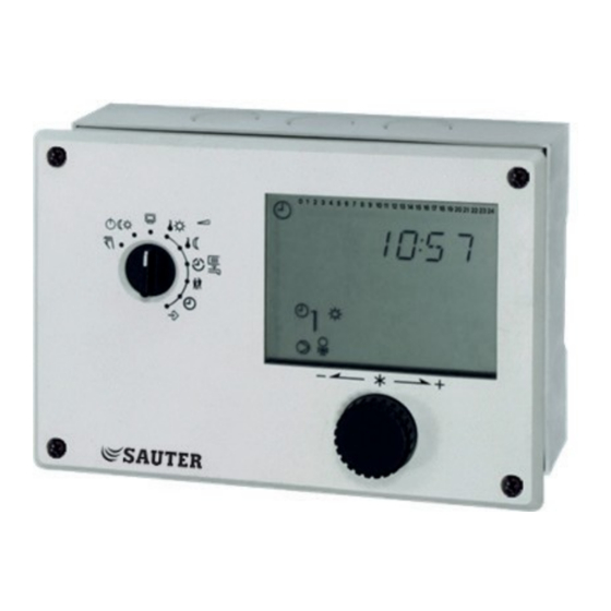
Short Instruction Manual Operating controls The operating controls are located on the front of the controller. Rotary pushbutton Turn: Press: Display, select parameters and function blocks Confirm adjusted selection or setting Rotary switch - Operating mode Information level, rotary switch in normal position Operating modes Manual mode: manual switching of pumps and valves, percentage setting... -
Page 5: Display
Short Instruction Manual Display The display indicates the time as well as information about the operation of the controller when the rotary switch is at the normal position (information level). The times-of-use together with temperatures of the various control circuits can be viewed on the display by turning the rotary pushbutton. -
Page 6: Operating Modes
Short Instruction Manual Operating modes Day mode (rated operation) Regardless of the programmed times-of-use and summer mode, the set points relevant for rated operation are used by the controller. Night mode (reduced Regardless of the programmed times-of-use, the set points relevant for reduced operation are used by the controller. - Page 7 Short Instruction Manual Check and setting the times-of-use Three times-of-use can be programmed for each day of the week. If only one time-of-use is required, the start and end times of the second time-of-use must be identical. The third time-of-use is then no longer displayed. If two time-of-use periods are required, the start and end times of the third time-of-use must be identical.
- Page 8 Short Instruction Manual Check and setting party mode With the Party mode function, the rated operation of the controller (day) - deviating from the set times-of-use - is continued or initiated for the duration of the set party timer. The party timer starts to run when the rotary switch is turned back to one of the operating mode positions.
- Page 9 Short Instruction Manual Systems System 1.0 Systems 1.1 bis 1.3 System 1.5 System 1.6 System 1.9 System 2.0 Systems 2.1 bis 2.3 Selection of types for DHW heating for systems 1.x and 2.x: Page 12 KA_EQJW146F001_EN011...
- Page 10 Short Instruction Manual System 3.0 System 3.5 System 4.0 System 4.1 System 4.5 System 10.0 System 11.0 System 11.1 KA_EQJW146F001_EN011...
- Page 11 Short Instruction Manual System 11.2 System 11.1/11.2 buffer storage System 11.5 System 11.6 System 11.9 System 16.0 System 16.1 System 16.2 KA_EQJW146F001_EN011...
- Page 12 Short Instruction Manual System 16.3 System 16.4 System 16.6 Types for DHW heating (systems 1.x and 2.x) Type 1 Type 2 Type 3 KA_EQJW146F001_EN011...
-
Page 13: Activating And Deactivating Functions
Short Instruction Manual Activating and deactivating functions A function is activated via the corresponding function block. The number sequence 0 to 24 at the top of the display represents the function block number. When a configuration level is called, the activated function blocks are identified by a black square on the right below the function block number. -
Page 14: Change Parameter
Short Instruction Manual Change parameter The parameters are arranged according to subject areas: PA1: Heating circuit 1 PA2: Heating circuit 2 PA4: DHW PA5: cross-system PA6: Communication Modbus Set rotary switch to parameter and functions; Parameter symbol flashes , Key number is displayed Turn the button;... -
Page 15: Manual Operation
Short Instruction Manual Manual operation Switch to manual mode to configure all outputs, refer to wiring diagram Select the display taking the control circuit into account.: POS1, POS2: Percentage setting of output value (HK1, HK2) UP1, UP2: Switching the circulation pump UP1, UP2 SLP: Switching the storage charging pump Switching the exchanger charging pump... -
Page 16: Function Block List
Short Instruction Manual Function block list CO1: Heating circuit 1 (HK1) (not system 1.9)* Function Comment Function block parameters / Range of values Room sensor RF1 CO1 -> F01 - 1: Room sensor RF1 active not systems 1.5, 1.6, 3.x Outdoor sensor AF1 CO1 ->... -
Page 17: Co2: Heating Circuit (Hk2) (Systems 3.X, 4.X And 10.0, 16.6)
Short Instruction Manual Function Comment Processing an CO1 -> F16 - 1: only with • CO1 -> F15 - 1 • CO1 -> F17 - 0 external demand, 0 to Function block parameters: 10 V 0 °C Lower transmission range: 0.0 to 130.0 °C Input term. -
Page 18: Co4: Dhw Circuit (Systems 1.1-1.3, 1.5, 1.6, 1.9, 2.X, 4.1, 4.5, 11.X )
Short Instruction Manual Funktion Bemerkung Control mode CO2 -> F12 - 1: three-step control Function block parameters: KP (proportional gain) / 0.1 to 50.0 120 s Tn (reset time) / 1 to 999 s TV (derivative-action time) / 0 to 999 s 45 s TY (valve transit time) / 5, 10, 15, …, 240 s CO2 ->... -
Page 19: Co5: System-Wide Functions (All Systems)
Short Instruction Manual Funktion Bemerkung Control mode CO24-> F12 - 1: three-step control (only 1.9, 11.x) Function block parameters: KP (proportional gain) / 0.1 to 50.0 (system. x.9: WE=0,6) 120 s Tn (reset time) / 1 to 999 s (system. x.9: WE=12 s) TV (derivative action time) / 0 s;... -
Page 20: Co6: Modbus
Short Instruction Manual Funktion Bemerkung Delayed outdoor CO5 -> F05, 06 - 1: Function block parameter: temperature adaptation when temperature 3,0 °C Delay per hour/ 1.0 to 6.0 °C decreases Delayed outdoor temperature adaptation when temperature increases Automatic summer Automatic summer/winter time changeover (last Sunday in March and October) time/winter time changeover Frost protection... -
Page 21: Co7: Device Bus (All Systems, F02, F03
Short Instruction Manual Funktion Bemerkung 11 Flow rate limitation in HK1 CO6 -> F11 - 1: Only with • CO6 -> F10 - 1 using meter bus CO5 -> F11 - 0 Function block parameters: 1,5 m³/h Maximum limit value /At, 0.01 to 650 m³/h 1,5 m³/h Maximum limit for heating operation* /At, 0.01 to 650 m³/h 1,5 m³/h... - Page 22 Function block parameter: Register No. / 5 to 64 20 "DHW heating CO7 -> F20 - 1: Sending of "DHW-heating active” active“ sending Function block parameter: Register No./ 5 bis 64 21 Receive release HK1 CO7 -> F21 - 1: Function block parameter: Register No.
-
Page 23: Parameter List
Short Instruction Manual Parameter lists PA1: Parameters HK1 (heating circuit 1) PA2: Parameters HK2 (heating circuit 2) Range of values WE Comment Parameter designation 0,2 to 3,2 Gradient, flow –30,0 to 30,0 °C 0,0 °C Level (parallel shift) –5,0 to 150,0 °C 20 °C Minimum flow temperature 5,0 to 150,0 °C... -
Page 24: Pa5: System-Wide Parameters (All Systems)
Short Instruction Manual PA5: system-wide parameters (all systems) Range of values WE Comment Parameter designation 20 to 90 °C 60 °C only 16.x Boiler pump on 0 to 30 °C 5 °C only 16.x switching difference 01.01 to 31.12 holidays 01.01 to 31.12 holiday periods PA6: Modbus... -
Page 25: Notes
Short Instruction Manual Item list Item no. Description EQJW146F001 Heating and district heating controller 0440210001 Adapter for connecting EQJW126/146 controllers to RS232 (PC) 0440210002 Adapter for connecting the EQJW126/146 controllers to modem 0440210003 Adapter for connecting EQJW126/146 controllers to RS485 bus...
Need help?
Do you have a question about the EQJW146F001 and is the answer not in the manual?
Questions and answers