
Related Manuals for sauter EQJW146F002


Summary of Contents for sauter EQJW146F002
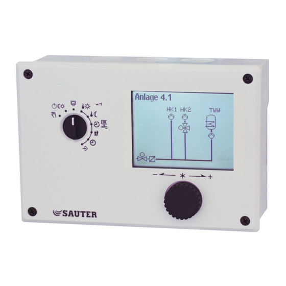
- Page 1 Shortmanual EQJW146F002 P100019102 Heating and District Heating Controller with graphics display Firmwareversion 2.4x...
- Page 2 Note on these mounting and operating instructions These mounting and operating instructions assist you in mounting and operating the device safely. The instructions are binding for handling SAUTER devices. Î For the safe and proper use of these instructions, read them carefully and keep them for later reference.
-
Page 3: Table Of Contents
Communication ............... 38 Memory module ................... 39 Installation ................40 Electrical connection ..............41 Appendix ................46 10.1 Function block lists ................46 10.2 Parameter lists ..................59 10.3 Resistance values .................. 65 10.4 Technical data ..................66 EQJW146F002 EN... -
Page 4: Safety Instructions
Select a suitable disposal method. Instead, dispose of your waste equipment by handing it over to a designated collection point for the recycling of waste electrical and electronic equipment. EQJW146F002 EN... -
Page 5: Operation
The rotary switch is used to set the operating mode and the relevant parameters for each control circuit. Operating level Operating modes Manual level Day set point (rated room temperature) Night set point (reduced room temperature) Times-of-use for heating/DHW Special time-of-use Time/date Settings EQJW146F002 EN... -
Page 6: Reading Information
Heating mode circuit Valve Circulation pump opens (heating) ON/OFF closes The following applies for DHW heating: Current Pump ON/OFF operating Storage tank charging pump mode Circulation pump (DHW) Solar circuit pump For further details, see section 2.3. EQJW146F002 EN... - Page 7 Alarm list The last four alarm entries are listed. ¼ Open the alarm list and select further alarm entries (q). Further information on an alarm (including time and date when it occurred) runs across the display. EQJW146F002 EN...
- Page 8 Details on the controller version (device identification, serial number, software and hard- ware versions) are displayed in the extended operating level. Turn the rotary switch to (settings). q Enter code number 1999. ¼ Confirm key number. Turn the rotary switch to (operating level). q Select 'Information'. EQJW146F002 EN...
-
Page 9: Adapting The Trend-Viewer
Shifting the time line: q Select 'Scroll'. ¼ Activate editing mode for scroll function. q Shift the time line. ¼ Confirm time display. Zooming in/out q Select 'Zoom'. ¼ Open zoom function. q Zoom in or out. ¼ Confirm display. EQJW146F002 EN... -
Page 10: Selecting Operating Modes
− Heating circuit HC1 − Heating circuit HC2 − DHW heating Î Only those control circuits are available for selection which can be controlled by the selected system. q Select the control circuit. EQJW146F002 EN... -
Page 11: Setting The Time And Date
24 hours. This is the case when the time blinks on the display. Turn the rotary switch to (time/date). The current time is selected (gray background). ¼ Activate editing mode for the time. The time reading is inverted. q Change the time. ¼ Confirm the time setting. EQJW146F002 EN... - Page 12 ¼ Activate editing mode for the date. The date reading is inverted. q Change date (day.month). ¼ Confirm the date setting. q Select 'Year'. ¼ Activate editing mode for the year. The year reading is inverted. q Change the year. ¼ Confirm the year setting. EQJW146F002 EN...
-
Page 13: Setting The Times-Of-Use
--:-- 00:00 to 24:00 h; in steps of 15 minutes Start third time-of-use --:-- --:-- 00:00 to 24:00 h; in steps of 15 minutes Stop third time-of-use --:-- --:-- 00:00 to 24:00 h; in steps of 15 minutes EQJW146F002 EN... - Page 14 The start time of the first time-of-use period can now be edited (inverted reading). q Change start time.(in steps of 15 minutes) ¼ Confirm the start time.The stop time of the first time-of- use period can now be edited. q End stop time.(in steps of 15 minutes) EQJW146F002 EN...
-
Page 15: Entering Day And Night Set Points
HC1 room temperature 20.0 °C 0.0 to 40.0 °C HC2 room temperature 20.0 °C 0.0 to 40.0 °C DHW temperature 60.0 °C Min. to max. DHW temperature HC1 OT deactivation value 22.0 °C 0.0 to 50.0 °C HC2 OT deactivation value 22.0 °C 0.0 to 50.0 °C EQJW146F002 EN... - Page 16 ¼ Activate editing mode for set point. q Adjust the set point. ¼ Confirm setting. Proceed in the same manner to adjust further set points. After adjusting all the set points: Turn the rotary switch back to (operating level). EQJW146F002 EN...
-
Page 17: Start-Up
(WE). Function block parameters and parameter level settings remain unchanged. The system code number is set in the configuration and parameter level. Turn the rotary switch to (settings). q Enter the currently valid key number. ¼ Confirm key number. EQJW146F002 EN... -
Page 18: Activating And Deactivating Functions
Turn the rotary switch to (settings). 3.2 Activating and deactivating functions A function is activated or deactivated in the associated function block. Turn the rotary switch to (settings). q Enter the currently valid key number. ¼ Confirm key number. EQJW146F002 EN... - Page 19 ¼ Confirm configuration. q Select function block parameter. ¼ Activate editing mode for function block parameter. The current setting is shown inverted on the display. q Set function block parameter. Proceed in the same manner to set further function blocks. EQJW146F002 EN...
-
Page 20: Changing Parameters
– PA2: Heating circuit HC2 – PA3: Not applicable – PA4: DHW heating – PA5: Not applicable – PA6: Modbus communication Î Only those parameter levels are available for selection which can be controlled by the selected system. EQJW146F002 EN... -
Page 21: Change Display Language
¼ Set current key number. / Confirm key number ¼ Select “Display language” ¼ Put display language into edit mode. The current language is selected ¼ Set language / confirm setting Turn the rotary switch back to the “Operating level” switch position. EQJW146F002 EN... -
Page 22: Loading Default Setting
The measured value number corresponds to the terminal number, e.g. measured value 3 = terminal 3 3.7 Keynumbers 1732 General parameter setting and configuration 1999 Enable/disable extended information level 1995 Change code number for parameterization and configuration 1991 Load factory setting 0002 Restart EQJW146F002 EN... -
Page 23: Manual Mode
Turn the rotary switch to mode is deactivated. Note The outputs of the controller are not affected by merely turning the rotary switch to (manual mode). The outputs are only changed by entering or changing the positioning values or switching states. EQJW146F002 EN... -
Page 24: Systems
DHW circuit include just one heat exchanger. These systems are Anl 1.0-1, 1.5-1, 1.6-1, 1.6-2, 1.9-1, 1.9-2, 2.x, 3.0, 3.5, 4.0, 4.1 and 16.x. The boiler can be controlled by an on/off output (CO1 > F12 - 0). Single-stage boiler RK1/10Vout RüF1 RK1_2 Pkt VF1 Fig. 1: Configuration of a boiler system EQJW146F002 EN... - Page 25 - 0 (without SF2) CO4 > F05 - 0 (without VF4) CO4 > F05 - 0 (without VF4) CO5 > F07 - 0 (without error message at terminal 29) CO5 > F07 - 0 (without error message at terminal 29) EQJW146F002 EN...
- Page 26 - 0 (without error message at terminal 29) CO1 > F02 - 1 (with AF1) CO1 > F03 - 1 (with RüF1) CO4 > F01 - 1 (with SF1) CO5 > F07 - 0 (without error message at terminal 29) EQJW146F002 EN...
- Page 27 - 1 (with SF2) CO4 > F05 - 0 (without VF4) CO4 > F05 - 0 (without VF4) CO5 > F07 - 0 (without error message at terminal 29) CO5 > F07 - 0 (without error message at terminal 29) EQJW146F002 EN...
- Page 28 - 1 (with SF2) CO4 > F02 - 0 (without SF2) CO4 > F05 - 0 (without VF4) CO5 > F07 - 0 (without error message at terminal 29) CO5 > F07 - 0 (without error message at terminal 29) EQJW146F002 EN...
- Page 29 CO1 > F02 - 1 (with AF1) CO1 > F03 - 1 (with RüF1) CO2 > F01 - 0 (without RF2) CO2 > F03 - 0 (without RüF2) CO5 > F07 - 0 (without error message at terminal 23) EQJW146F002 EN...
- Page 30 - 1 (with RüF2) CO2 > F01 - 0 (without RF2) CO5 > F07 - 0 (without error message at terminal 23) CO2 > F03 - 1 (with RüF2) CO5 > F07 - 0 (without error message at terminal 23) EQJW146F002 EN...
- Page 31 - 0 (without SF2) - 1 (with SF2) CO4 > F01 - 1 (with SF1) CO4 > F03 - 0 (without RüF2) - 0 (without RüF2) CO4 > F02 - 0 (without SF2) CO4 > F03 - 0 (without RüF2) EQJW146F002 EN...
- Page 32 CO5 > F07 - 0 (without error message at terminal 23) CO1 > F03 - 1 (with RüF1) CO4 > F01 - 1 (with SF1) CO4 > F02 - 1 (with SF2) CO4 > F03 - 0 (without RüF2) EQJW146F002 EN...
- Page 33 - 1 (with AF1) CO1 > F03 - 1 (with RüF1) CO1 > F03 - 1 (with RüF1) CO5 > F07 - 0 (without error message at terminal 29) CO5 > F07 - 0 (without error message at terminal 29) EQJW146F002 EN...
- Page 34 CO1 > F03 - 1 (with RüF1) CO1 > F03 - 1 (with RüF1) CO5 > F07 - 0 (without error message at terminal 29) CO2 > F02 - 0 (without AF2 for RK2) CO2 > F03 - 0 (without RüF2) EQJW146F002 EN...
-
Page 35: Operational Faults
Heat meter = Heat meter error registered Note If the error messages or indications that can be confirmed are included in the list shown, you can decide whether you want to confirm these error messages on exiting the error list. EQJW146F002 EN... -
Page 36: Sensor Failure
6.3 Temperature monitoring When a system deviation greater than 10 °C persists in a control circuit for 30 minutes, an "Err 6" message (temperature monitoring alarm) is generated. Functions Configuration Monitoring CO5 > F19 - 1 EQJW146F002 EN... -
Page 37: Error Status Register
Decimal value Sensor failure – Disinfection Max. charging temp. External Temp. monitoring Unauthorized access Binary alarm Meter bus Heat meter Total Example: Value of error status register when a sensor fails and a temperature monitor- ing alarm = EQJW146F002 EN... -
Page 38: Communication
Communication 7 Communication Using the optional controller EQJW126/146 communication module, the SAUTER EQJW146F002 Heating Controller can communicate with a control system. In combination with a suitable software for process visualization and communication, a complete control system can be implemented. The following communication variants are possible: •... -
Page 39: Memory Module
7.1 Memory module A memory module ( 0440210010) is particularly useful for transferring all the set data from one EQJW146F002 controller to several other EQJW146F002 controllers. The memory module is connected to the RJ-45 socket on the side. After connection, "Save settings" appears in the control- ler display. -
Page 40: Installation
144 x 98 x 75 The controller consists of the housing with the electronics and the back panel with the ter- minals. It is suitable for panel, wall and top hat rail mounting (see Fig. 2). Panel mounting Wall mounting Rail mounting EQJW146F002 EN... -
Page 41: Electrical Connection
Such measures are indis- pensable for bus lines. − The shield of signal lines installed outside buildings must have current conducting ca- pacity and must be grounded on both sides. − Surge diverters must be installed at the control cabinet inlet. EQJW146F002 EN... - Page 42 The electric actuators and pumps are not automatically supplied with a voltage by the controller. They can be connected over terminals 20, 22, 25 and 28 to an external volt- age source. If this is not the case, connect a jumper from terminal 18 to terminals 20, 22, 25 and 28. EQJW146F002 EN...
- Page 43 Binary input Control circuit Potentiometer Circulation pump (heating) Room sensor Storage tank charging pump RüF Return flow sensor Heat exchanger charging pump Storage tank sensor Circulation pump (DHW) Flow sensor Fig. 2: Connection of SAUTER EQJW146F002 Controller with standard base EQJW146F002 EN...
-
Page 44: Appendix
(only with CO1 > F01 - 1 and CO1 > F02 - 1) 3.x, 16.x 08 Adaptation Not systems CO1 > F08 - 1: Heating characteristic adaptation Anl. 1.5, 1.6, (only with CO1 > F01 - 1, CO1 > F02 - 1 and CO1 > 3.x, 16.x F11 - 0) EQJW146F002 EN... - Page 45 0 to signal (only with CO1 > F15 - 1 and CO1 > F17 - 0) 10 V Function block parameters: Terminals Lower transmission range: 0 to 150 °C (0 °C) 11/12 Upper transmission range: 0 to 150 °C (120 °C) EQJW146F002 EN...
- Page 46 Function block parameters: Set point of differential temperature control: 0.0 to 50.0 °C (20.0 °C) KP (influence factor): 0.1 to 10.0 (1.0) Minimum speed: 0 to 100 % (20 %) F Function block number, WE Default setting, Anl System code number EQJW146F002 EN...
- Page 47 Cycle time: 0 or 1 to 100 min (20 min) KP (gain): 0.0 to 25.0 (0.0) 11 Four-point CO2 > F11 - 1: Four-point characteristic (only with CO2 All* characteristic > F08 - 0) CO2 > F11 - 0: Gradient characteristic EQJW146F002 EN...
- Page 48 CO4 > F01 - 1: Storage tank sensor SF1 1.6, 2.x, 4.1, sensor 1 CO4 > F01 - 0: Storage tank thermostat 4.5, 11.0, (only with CO4 > F02 - 0; not system Anl 11.0) 11.2 1.9, 11.9 EQJW146F002 EN...
- Page 49 CO4 > F09 - 1: Priority through set-back operation 1.1–1.3, 4.1, 4.5, 11.x (set-back) (only when CO4 > F08 - 0) Function block parameters: Start: 0 to 10 min (2 min) Control circuit: HC1, HC2, HC1+HC2 (only system Anl 4.5) EQJW146F002 EN...
- Page 50 2.3, 4.1, 11.1 ing on return less return flow hot (only with CO1 > F03 - 1 for systems flow tempera- Anl 1.5, 2.0, 2.1, 2.3, 4.1; only with CO4 > F03 - 1 for ture system Anl 11.1) EQJW146F002 EN...
- Page 51 CO5 > F04 - 1: Summer mode Anl 1.5, 1.6, mode Function block parameters: 1.9, 3.5 Time: Adjustable as required (01.06. - 30.09.) No. days until activation: 1 to 3 (2) No. days until deactivation: 1 to 3 (1) Limit: 0.0 to 30.0 °C (18.0 °C) EQJW146F002 EN...
- Page 52 Active when BI = ON, OFF (ON) 14 Operation CO5 > F14 - 1: Feeder pump UP1 operation to cover 3.0, 16.x own demand Note: the feeder pump UP1 also starts to operate to cov- er the demand of RK2. EQJW146F002 EN...
- Page 53 CO5 > F25 - 1: 0 V/0 % = Valve OPEN/pump with max. delivery rate Function block parameters: Zero: 0 to 50 % (0 %) 31 AI1 Zero All* CO5 > F31 - 0 shift Function block parameters: Zero: 5 to 20 % (5 %) F Function block number, WE Default setting, Anl System code number EQJW146F002 EN...
- Page 54 CO6 > F20 - 1: Various Modbus specifications do not out building have any effect on the collective level/building automa- automation tion system reading system * Not systems Anl 1.0, 1.5–1.9, 3.0, 3.5, 4.0, 10.0, 11.x F Function block number, WE Default setting, Anl System code number EQJW146F002 EN...
- Page 55 PA4 level Function block parameters: Register number/5 to 64 (5) 14 Send max. de- CO7 -> F14 - 1: the controller already determines inter- mand nally the maximum flow set point of its circuit and sends it this value to the primary controllers EQJW146F002 EN...
- Page 56 CO8 > F01 - 1: Analysis active Function block parameters: Error message when BI = 0, BI = 1, none (1) CO8 > F02 - 1: Analysis active 02 Analysis of Function block parameters: Error message when BI = 0, BI = 1, none (1) EQJW146F002 EN...
-
Page 57: Parameter Lists
Reduced flow temperature: –5.0 to 150.0 °C (60.0 °C, 40.0 °C, 20.0 °C, 20.0 °C) with CO1 > F04 -1: (30 °C, 25 °C, 20 °C, 15 °C) Return flow temperature: 5.0 to 90.0 °C (65.0 °C, 65.0 °C, 65.0 °C, 65.0 °C) Flow rate: 0.01 to 650 m³/h (0.00 m³/h, 0.00 m³/h, 0.00 m³/h, 0.00 m³/h) EQJW146F002 EN... - Page 58 OT to 90.0 °C (AT), only HC 1 Stop charging of the buffer tank: OT to 90.0 °C (AT), only HC 1 Charging temperature boost: 0.0 to 50.0 °C (6.0 °C), only HC 1 Lag time of charging pump 0.0 to 10.0 (1.0), only HC 1 EQJW146F002 EN...
- Page 59 Lag time for storage tank charging pump (= Valve transit time x P19): 0.0 to 10.0 (1.0) PA5: System-wide parameters Display reading Parameter: Value range (default setting) Start temperature for boiler pump (system Anl 16.x only) 20.0 to 90.0 °C (60.0 °C) EQJW146F002 EN...
- Page 60 Boiler pump hysteresis (system Anl 16.x only) 0.0 to 30.0 °C (5.0 °C) PA6: Modbus Display reading Parameter: Value range (default setting) Modbus station address (8 bit): 1 to 246 (255) 1 to 3200 (255) with CO6 > F02 - 1 EQJW146F002 EN...
-
Page 61: Resistance Values
–40 –30 –20 –10 Resistance Ω 1000 1056 1112 1171 1230 Temperature °C Resistance Ω 1291 1353 1417 1483 1549 1618 1688 1760 1833 1909 1986 Temperature °C Resistance Ω 2066 2148 2232 2318 2407 2498 2592 2689 2789 2892 EQJW146F002 EN... -
Page 62: Technical Data
Humidity rating F according to VDE 40040 Noise immunity According to EN 61000-6-1 Noise emission According to EN 61000-6-3 Weight Approx. 0.5 kg Compliance · * For systems with one control circuit, a maximum of four pumps are available. EQJW146F002 EN... - Page 63 EQJW146F002 SAUTER Deutschland Sauter-Cumulus GmbH Hans-Bunte-Str. 15 79108 Freiburg http://www.sauter-cumulus.de Telefon +49 (761) 5105-0 Telefax +49 (761) 5105-234 E-Mail: sauter-cumulus@de.sauter-bc.com Revision no: A, date: 20.05.2021...
Need help?
Do you have a question about the EQJW146F002 and is the answer not in the manual?
Questions and answers