Sign In
Upload
Download
Table of Contents
Contents
Add to my manuals
Delete from my manuals
Share
URL of this page:
HTML Link:
Bookmark this page
Add
Manual will be automatically added to "My Manuals"
Print this page
×
Bookmark added
×
Added to my manuals
Manuals
Brands
sauter Manuals
Controller
EQJW145
Operating manual
sauter EQJW145 Operating Manual
Heating controller
Hide thumbs
1
2
3
4
5
6
7
8
9
10
11
12
13
14
15
16
17
18
19
20
21
22
23
24
25
26
27
28
29
30
31
32
33
34
35
36
37
38
39
40
41
42
43
44
45
46
47
48
49
50
51
52
53
54
55
56
57
58
59
60
61
62
63
64
65
66
67
68
69
70
71
72
73
74
75
76
77
78
79
80
81
82
83
84
85
86
87
88
89
90
91
92
93
94
95
96
97
98
99
100
101
102
103
104
105
106
107
108
109
110
page
of
110
Go
/
110
Contents
Table of Contents
Bookmarks
Table of Contents
Table of Contents
Symbols Used in this Manual
1 General Information
Introduction
Safety Information
2 Description of the Operating Controls
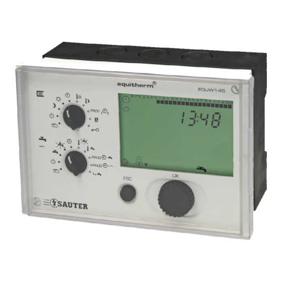
Front View of the EQJW 145
Fig. 1: EQJW 145 - Front View
Top Rotary Switches (Heating)
Bottom Rotary Switch (Hot Water/Pilot Timer)
Fig. 2: EQJW 145 - Top Rotary Switches
Fig. 3: EQJW 145 - Bottom Rotary Switches
Input Knob
ESC Key
Display
3 Commissioning
Operating the Device for the First Time
Setting the Time
Setting the Date
Commissioning Level
List of Service Parameters
Tab. 1: Service Parameter
Access to Commissioning Level
View Service Parameters
Change Service Parameters
Service Level
Access to Service Level
View Service Parameters
Change Service Parameters
List of Service Parameters
Tab. 2: Service Parameter
Explanations for Individual Service Parameters
Fig. 4: Limitation Function
Tab. 3: DHW Preparation
Fig. 5: Guideline for the Slope of the Heating Characteristic
Communication Level
Access to Communication Level
Viewing the Communication Parameters
Changing Communication Parameters
List of Communication Parameters
Tab. 4: Communication Parameters
Explanations of Individual Communication Parameters
4 Operation
Operating Modes
Displays When Automatic Mode Is Set
Displays When Back-Up Mode, Reduced Mode and Normal Mode Are Set50
Entering the Setpoint Temperature in Normal Mode
Enter Setpoint Temperature in Reduced Mode
Weekly Switching Programme for Heating
Calling up the Weekly Switching Programme
View Switching Commands
Enter a Switching Command
Changing and Deleting a Switching Command
Calendar Switching Programme
Calling up the Calendar Switching Programme
View Switching Commands
Enter a Switching Command
Changing and Deleting a Switching Command
Temporary Temperature Change for the Heating Circuit
Entering DHW Temperatures
Notes on the Boosted DHW Temperature
Weekly Switching Programme for Domestic Hot Water
Tab. 5: Statuses for Domestic Hot Water
Calling up the Weekly Switching Programme
View Switching Commands
Enter a Switching Command
Changing and Deleting a Switching Command
Weekly Switching Programme for Pilot Timer/Circulating Pump
Calling up the Weekly Switching Programme
View Switching Command
Enter Switching Command
Change/Delete Switching Command
Once-Only Tank Charge
5 Manual Mode
Access to Manual Mode (Heating)
Access to Manual Mode (Domestic Hot Water, Configurable Output and Second Final Control Element)
Set Valve Position
Set Status of Other Outputs (Pumps, Configurable Output) for Manual Mode
Exit Manual Mode
Check Measured Values in Manual Mode
6 Communication Functions
Bus Wiring
Device Bus
Assigning Addresses
Room Operating Unit EDB 100
Sending and Receiving Outdoor Temperatures
Requesting and Processing a Heat Requirement
Requesting and Processing a Return Temperature
Synchronising the Time
Modbus Communication
Fig. 6: Modbus Communication-Commandos
Modbus Data Points (Holding Register)
Tab. 6: Modbus Data Points
Tab. 7: Switching Commands
Modbus Data Points (Coils)
Modem Operation
Connection with the Modem
Modbus Operation Via Modem
Tab. 8: Modbus Data Points Coils
Sending SMS if There Is a Fault on the Installation
Displays for Modem Operation
Setting Parameters Using the PC
Tab. 9: Display for Modem Operation
7 Faults
Displaying Faults
Error List
Device Status
Tab. 10: Error List
Logbook
Reset Functions
Actions to Deal with Faulty Temperature Value Measurements
8 Using the Controller
General Information
Examples of Use
Control Model 1
Fig. 7: EQJW 145 Control Model 1
Fig. 8: EQJW 145 Control Model 1
Fig. 9: EQJW 145 Control Model 1
Control Model 2
Fig. 10: EQJW 145 Control Model 2
Control Model 3
Fig. 11: EQJW 145 Control Model 3
9 Economy Tips
Fig. 12: Consumers of Energy in the Household
10 Resistance Values for the Ni1000 Sensors
Tab. 11: Resistance Value Ni1000
11 Accessories
12 Wiring Diagram
13 Dimension Drawing
Fig. 13: Wiring Diagram
Fig. 14: Dimension Drawing of EQJW 145
14 Technical Data
Overview of Technical Data
Tab. 12: Overview of Technical Data
Overview of Main Functions
15 Overview of Controller Settings
List of Service Parameters
Tab. 13: List of Service Parameters
Tab. 14: List of Communication Parameters
Weekly Switching Programme: Heating
Weekly Switching Programme: Domestic Hot Water
Table of Figures
List of Tables
Abbreviations
Index
Advertisement
Quick Links
1
Front View of the Eqjw 145
Download this manual
R
EQJW145: Heating
controller
Operating manual
7010015003 A
Table of
Contents
Previous
Page
Next
Page
1
2
3
4
5
Advertisement
Chapters
Table of Contents
3
Table of Figures
105
Table of Contents
Need help?
Do you have a question about the EQJW145 and is the answer not in the manual?
Ask a question
Questions and answers
Related Manuals for sauter EQJW145
Controller sauter equitherm EQJW 125 User Manual
Heating controller (74 pages)
Controller sauter Equitherm Operating Manual
Heating controller (110 pages)
Controller sauter EQJW146F001 Short Instruction Manual
Heating and district heating controller (25 pages)
Controller sauter EQJW146F001 Short Manual
Heating and district heating controller (53 pages)
Controller sauter equitherm EQJW245 Operating Manual
Electronic heating controller (127 pages)
Controller sauter equitherm EQJW245 Quick Reference
Electronic heating controller (7 pages)
Controller sauter equitherm EQJW126F001 Mounting And Operating Instructions
Heating and district heating controller (110 pages)
Controller sauter EQJW146F002 Manual
Heating and district heating, with graphics display (160 pages)
Controller sauter EQJW146F002 Short Manual
Heating and district heating controller with graphics display (63 pages)
Controller sauter EQJW 246 Short Manual
Heating and district heating controller with graphics display (32 pages)
Controller sauter SAUTER flexotron 400 Manual
(36 pages)
Controller sauter flexotron 700 User Manual
(7 pages)
Controller sauter equitherm M60 Operating Instructions Manual
Heating controller (64 pages)
Controller sauter NRT405F901 Manual
(50 pages)
Controller sauter RDT 921 F901 Hardware Manual
Configurable controllers (38 pages)
Controller sauter flexotron 800 Series Manual
Ventilation (122 pages)
This manual is also suitable for:
Equitherm
Table of Contents
Print
Rename the bookmark
Delete bookmark?
Delete from my manuals?
Login
Sign In
OR
Sign in with Facebook
Sign in with Google
Upload manual
Upload from disk
Upload from URL


Need help?
Do you have a question about the EQJW145 and is the answer not in the manual?
Questions and answers