Table of Contents
Advertisement
Advertisement
Chapters
Table of Contents

Related Manuals for sauter NRT405F901


Summary of Contents for sauter NRT405F901
- Page 1 SAUTER ITALIA SPA NRT405F901...
-
Page 2: Table Of Contents
The information in this document is subject to change without prior notification. The software described in this document is supplied under licence by SAUTER ITALIA SPA and may be used or copied only in accordance with the terms of the licence. -
Page 3: Part I Introduction
Part I Introduction Table of contents CHAPTER 1 ABOUT THIS MANUAL ..................4 Terms ..........................4 Additional information ..................... 4 CHAPTER 2 INTRODUCTION TO NRT405F901 ............... 5 ......................... 5 AN COIL CONTROLLER ........................5 OMMUNICATION CHAPTER 3 FUNCTIONS ....................... 7 Design .......................... -
Page 4: Chapter 1 About This Manual
Factory setting Additional information Additional information concerning NRT405F901can be found in: • Manual NRT tool – Describes how to configure the controller The information is available for download from SAUTER ITALIA SPA's website, www.sauteritalia.it. NRT405F901 manual Chapter 1 About this manual... -
Page 5: Chapter 2 Introduction To Nrt405F901
Chapter 2 Introduction to NRT405F901 Fan coil controller NRT405F901 is a fan coil controller for control of heating, cooling and fan control. NRT405F901 enables you to create anything from stand-alone systems for managing the functions in a single room to large, integrated SCADA systems. - Page 6 Application examples NRT405F901 manual Chapter 2 Introduction to NRT405F901...
-
Page 7: Chapter 3 Functions
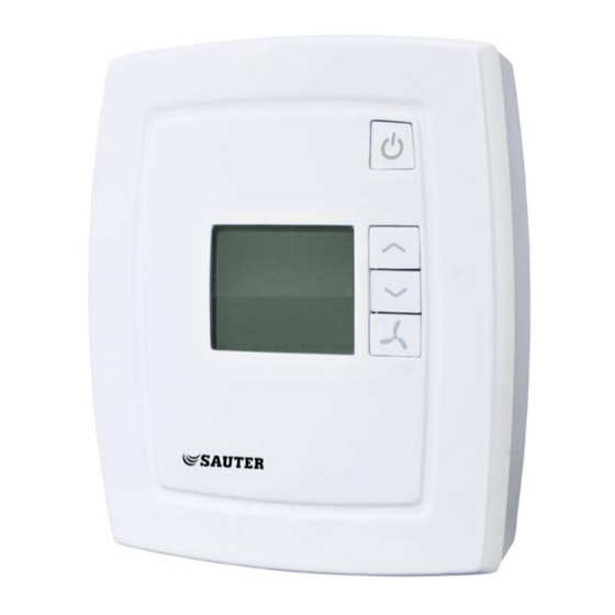
Chapter 3 Functions ● ● ● ● ● ● NRT405F901 Table 1. The control functions Design Figure 1. NRT405F901 NRT405F901 manual Chapter 3 Functions... -
Page 8: Chapter 4 Technical Data
AI ............. External PT1000 sensor instead of the internal NTC UI ........Change-over input; potential-free switch (configurable for NO/NC ...........................or PT1000 DI ........Digital input; potential-free window contact or occupancy contact, ......................configurable for NO/NC. NRT405F901 manual Chapter 4 Technical data... -
Page 9: Accessories For Nrt405F901
Accessories for NRT405F901 External temperature sensor ................. EGT456F101 Change-over ................EGT456F101, RAM100F001 The accessories are available from SAUTER ITALIA SPA. For more detailed information concerning these accessories, see the individual product sheet and instruction for each product, available via www.sauteritalia.it. -
Page 10: Part Ii Installation
SING LABELS ........................12 ONFIGURATION CHAPTER 6 INSTALLATION ....................13 ..........................13 OUNTING ......................13 OMMUNICATION WIRING Bottom plate connections ..................... 14 Wiring for NRT405F901 ....................15 Wiring of various actuators ................... 16 CHAPTER 7 COMMISSIONING ................... 17 Troubleshooting......................17... -
Page 11: Chapter 5 Preparations For Installation
If the label address is 191:183, the following addresses are used for the different communication protocols: PLA=191, ELA=183. Modbus: Address=183. BACnet: Device ID=191183 (the 4 low digits=1183, the 3 high digits=19), MS/TP MAC address=83. NRT405F901 manual Chapter 5 Preparations for installation... -
Page 12: Configuration
For more information on configuring, see the chapter Configuration. The bottom plate containing information on placement and wiring can be sent separately to the building for electrical installation. NRT405F901 manual Chapter 5 Preparations for installation... -
Page 13: Chapter 6 Installation
NOTE: Do not fasten the screws too tightly! Communication, wiring The communication cable must be a screened, twisted pair cable. If the length of the loop exceeds 300 m, a repeater is required. See figure below: Figure 5. Wiring NRT405F901 manual Chapter 6 Installation... -
Page 14: Bottom Plate Connections
Bottom plate connections Figure 6. Bottom plate connections NRT405F901 manual Chapter 6 Installation... -
Page 15: Wiring For Nrt405F901
Wiring for NRT405F901 Wiring of thermal actuator Wiring of electric heater with solid state-relay (NRT405F901) (NRT405F901) Wiring of electric heater with solid state relay Wiring of 3-position actuator (NRT405F901) (NRT405F901) NRT405F901 manual Chapter 6 Installation... -
Page 16: Wiring Of Various Actuators
External PT1000 instead of the internal NTC Universal input Change-over input. Floating (potential-free) switch (configurable for NO/NC) or PT1000. AGnd Analogue ground AGnd Analogue ground Not connected Not connected RS485 communication A NRT405F901 RS485 communication B NRT405F901 NRT405F901 manual Chapter 6 Installation... -
Page 17: Chapter 7 Commissioning
This means that the built-in safety functions cannot be deactivated. The controller has different types of indications which can be used to support troubleshooting. See section Indications. NRT405F901 manual Chapter 7 Commissioning... -
Page 18: Part Iii Configuration
Part III Configuration Table of contents CHAPTER 8 CONTROL PRINCIPLES ..................19 CHAPTER 9 OPERATING MODES ..................21 ....................21 IFFERENT OPERATING MODES ....................... 21 CCUPANCY CONTROL CHAPTER 10 BUTTON MANAGEMENT ................22 CHAPTER 11 TYPES OF ACTUATORS................... 24 CHAPTER 12 FAN CONTROL ....................25 CHAPTER 13 CHANGE-OVER .................... -
Page 19: Chapter 8 Control Principles
During control of cooling, the output starts to increase when the temperature rises above the setpoint value. Control principle for heating function, 2-pipe installations During control of heating, the output starts to increase when the temperature falls below the setpoint value. NRT405F901 manual Chapter 8 Control principles... - Page 20 The above schematic drawings of the control principle show the corresponding requirement of the controller function. This requirement is recalculated by the controller to a value for the actuator output, depending on the selected output function. NRT405F901 manual Chapter 8 Control principles...
-
Page 21: Chapter 9 Operating Modes
Occupancy control Parameter 3 decides whether DI is the input for a window contact or a presence detector. A presence detector can be connected to DI in order to choose between Comfort and Economy mode. NRT405F901 manual Chapter 9 Operating modes... -
Page 22: Chapter 10 Button Management
Increase setpoint Decrease setpoint Fan speed On/Off button By pressing the On/Off button, NRT405F901 will switch between Off mode and Comfort/Economy mode. Setpointbuttons The INCREASE and DECREASE buttons are used to change the setpoint value. The desired contents of the display can be configured via the parameter list. There are four alternatives:... - Page 23 In parameter 34 and 35 it is possible to set the maximum permitted increase as well as decrease of the setpoint. Example: If P35=5 and P34=3, the setpoint can be adjusted between 17°C and 25°C (see the picture below). NRT405F901 manual Chapter 10 Button management...
-
Page 24: Chapter 11 Types Of Actuators
Chapter 11 Types of actuators NRT405F901 can be used with two types of actuators: • Thermal actuators • 3-point actuators (Increase/decrease actuators) The type of actuator is configured using NRT tool or in the parameter menu of the display. Thermal actuators When control of a thermal actuator has been selected, it is controlled digitally through output DO... -
Page 25: Chapter 12 Fan Control
However, it will continue to run if mould protection has been configured. If the fan has been configured not to be affected by the controller output (parameter 25), the ”Auto” option will not be shown when pressing the fan button. NRT405F901 manual Chapter 12 Fan control... - Page 26 When this function has been configured, the fan will always run at the lowest speed and circulate air in the room to minimise the risk of mould growth in the fan-coil unit. The function is deactivated on delivery. NRT405F901 manual Chapter 12 Fan control...
-
Page 27: Chapter 13 Change-Over
DO4. If the temperature rises above 28°C (FS), the change-over function is turned off and heating is controlled on the output. Change-over can also be controlled via a central command. See list of variables contained in Part IV. NRT405F901 manual Chapter 13 Change-over... -
Page 28: Chapter 14 Display Handling
Before the change is confirmed, the original value (i.e. the value from before the change took place) can be returned by pressing the INCREASE and DECREASE buttons simultaneously. The original value will then return in the display. NRT405F901 manual Chapter 14 Display handling... - Page 29 0=Internal sensor 1=External room sensor Sensor connected to UI1: 0=None 1=Change-over digital 2=Change-over analogue Type of digital actuator: 0=Thermal 1=3-position Output signal for actuator connected to AO1: 0=0…10 V 1=2…10 V 2=10…2 V 3=10…0 V NRT405F901 manual Chapter 14 Display handling...
- Page 30 Maximum permitted upward setpoint offset. Settable value=0...13 K. Maximum permitted downward setpoint offset. Settable value=0...17 K. NO/NC* digital input 1: 0=NO 1=NC NO/NC* universal input 1: 0=NO 1=NC NO/NC* digital output 4: 0=NO 1=NC NO/NC* digital output 5: 0=NO 1=NC NRT405F901 manual Chapter 14 Display handling...
- Page 31 3 = 76800 bps Set communication parameters to factory settings (does not apply to addresses): 1 = Factory settings (Modbus@9600 ) Basic setpoint for NRT405F901, 5…50°C Table 13. Parameter list *NO = Normally Open, NC = Normally Closed NRT405F901 manual...
-
Page 32: Chapter 15 Memory Functions During Power Failure
- will however present no problems. Example Activating the occupancy detection will not be saved to memory. Rather, the controller will return to its current mode after powering up. NRT405F901 manual Chapter 15 Memory functions during power failure... -
Page 33: Part Iv Signals
Part IV Signals Table of contents CHAPTER 16 MODBUS SIGNAL TYPES ................34 CHAPTER 17 MODBUS SIGNALS ..................36 ........................36 ISCRETE INPUTS ....................... 37 OIL STATUS REGISTER ........................38 NPUT REGISTER ........................39 OLDING REGISTER CHAPTER 18 BACNET SIGNAL TYPES .................. 43 CHAPTER 19 BACNET SIGNALS .................. -
Page 34: Chapter 16 Modbus Signal Types
B on the RS485 unit. It is usually easiest to find out what fits where simply by experimenting. Wrong polarity makes the system not function, but is incapable of harming any unit. NRT405F901 manual Chapter 16 Modbus signal types... - Page 35 If odd or even parity is set only one stop bit will be used, or the total amount of bits will be too great. 1 start bit, 8 data bits, 1 parity bit and 1 stop bit gives a total of 11 bits, which is the maximum. NRT405F901 manual Chapter 16 Modbus signal types...
-
Page 36: Chapter 17 Modbus Signals
Indicates change-over status from analogue input RC_Actual_L.NRTChangeOverState Indicates change-over status from both digital and analogue input Not used in this model 29-30 RC_Actual_L. NRTPresence Occupancy indication (with on- and switch-off delay) Not used in this model 32-33 NRT405F901 manual Chapter 17 Modbus signals... -
Page 37: Coil Status Register
Not used in this model RC_Setp_L.NRTComFactoryDefaults Set communication parameters to factory settings (does not apply to addresses): 1 = Factory settings (resets to 0) NRT405F901 manual Chapter 17 Modbus signals... -
Page 38: Input Register
Heating output signal (0…100 %) RC_Actual_R.NRTCoolOutput Cooling output signal (0…100 %) RC_Actual_R.NRTAI1Raw Raw value for analogue input 1 RC_Actual_R.NRTUI1Raw Raw value for universal input 1 RC_Actual_R.RoomTemp_NRT2 Room temperature input value from secondary internal sensor NRT405F901 manual Chapter 17 Modbus signals... -
Page 39: Holding Register
2 = Economy/Standby 3 = Presence 5 = No remote control RC_Setp_X.NRTUnitReturnState Pre-set running mode: 0 = Off 1 = Standby RC_Setp_X.NRTUnitShutDownState Shutdown mode: 0 = Off 1 = Standby Not used in this model NRT405F901 manual Chapter 17 Modbus signals... - Page 40 Modbus parity bit: 0 = No parity 1 = Odd parity 2 = Even parity RC_Setp_X.NRTModbusCharTimeout Modbus timeout for characters (t1.5), in ms. Should be 1.5 times a character, ie. at least 2 ms. NRT405F901 manual Chapter 17 Modbus signals...
- Page 41 Max. upward setpoint offset RC_Setp_R.NRTSetpointOffsetNeg 17°C Max. downward setpoint offset Not used in this model RC_Setp_R.NRTPIDPGain 10°C Room controller P-band RC_Setp_R.NRTPIDITime 300 sec Room controller I time RC_Setp_R.NRTCVDeadband Not used (Control valve dead band) NRT405F901 manual Chapter 17 Modbus signals...
- Page 42 Not used in this model RC_Setp_R.NRTHeatOutputManual Manual output heating output (0…100 %) RC_Setp_R.NRTCoolOutputManual Manual output cooling output (0…100 %) RC_Setp_R.NRTRoomTempRemote -255 Used for remote control of room temperature. External Room sensor must be selected. RC_SetpExt_R.NRTSetPoint 22°C Basic setpoint NRT405F901 manual Chapter 17 Modbus signals...
-
Page 43: Bac Net Signal Types
The property out_of_service is not writable for all Object Types. Commandable The value objects are not commandable (i.e. does not use a priority array). EDE files EDE files for BACnet are included in the NRT tool installation. NRT405F901 manual Chapter 18 BACnet signal types... -
Page 44: Bac Net Signals
Not used in this model Analog value, 11-12 RC_Setp_R.NRTHeatOutputManual Analog value, 13 Manual value heating output RC_Setp_R.NRTCoolOutputManual Analog value, 14 Manual value cooling output RC_Setp_R.NRTRoomTempRemote Analog value,15 Remote control of room °C temperature. NRT405F901 manual Chapter 19 BACnet signals... -
Page 45: Binary Inputs
ACTIVE/ INACTIVE RC_Actual_L.NRTCVHeatDec Binary value, 4 Indicates heating decrease ACTIVE/ INACTIVE Not used in this model Binary value, 5-6 RC_Actual_L.NRTChangeOverState Binary value, 7 Indicates change-over status ACTIVE/ from both digital and INACTIVE analogue input NRT405F901 manual Chapter 19 BACnet signals... -
Page 46: Loop
Current running 1=Off mode 2=Unoccupied 3=Stand-by 4=Occupied 5=Bypass RC_Actual_X.NRTControllerState Multistate input, 2 Current control 1=Off mode 2=Heating 3=Cooling RC_Actual_X.NRTFanSpeed Multistate input, 3 Current fan speed 1=Off 2=Fan speed 1 3=Fan speed 2 4=Fan speed 3 NRT405F901 manual Chapter 19 BACnet signals... -
Page 47: Multistate Values
6=No remote control Device The Device object contains to writeable properties; Description and Location. Description can be 17 characters in length and Location can be 33 characters, as long as single byte character encoding is used. NRT405F901 manual Chapter 19 BACnet signals... -
Page 48: Part V Index
Analogue, 45 3-position actuators, 24 Binary, 46 Discrete, 37 Multistate, 47 Installation, 13 About this manual Introduction to NRT405F901, 5 Additional information, 4 Terms, 4 Additional information, 4 Analogue values, 45 Loop, 47 Application examples, 6 Memory functions during power failure, 33... - Page 49 3-position actuators, 24 Excercising, 24 Wiring Thermal actuators, 24 communication, 13 Wiring for NRT405F901, 15 Using labels, 11...
- Page 50 SAUTER - your local partner. www.sauteritalia.it...
Need help?
Do you have a question about the NRT405F901 and is the answer not in the manual?
Questions and answers