
Related Manuals for sauter equitherm EQJW245


Summary of Contents for sauter equitherm EQJW245
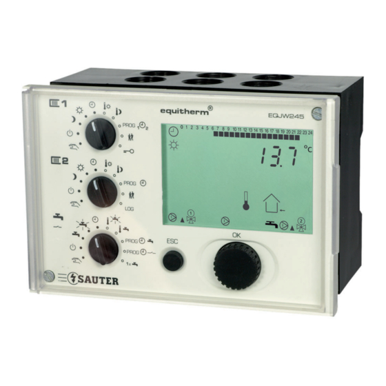
- Page 1 ® SAUTER equitherm EQJW245 Electronic heating controller Operating manual 7010042003 A www.sauter-controls.com...
-
Page 2: Control Model
EQJW245 2/127 www.sauter-controls.com... -
Page 3: Table Of Contents
Operating modes 4.1.1 Displays when automatic mode is set 4.1.2 Displays when back-up mode, reduced mode and normal mode are Entering the setpoint temperature in normal mode Enter setpoint temperature in reduced mode Weekly switching programme for heating www.sauter-controls.com 3/127... - Page 4 Sending and receiving outdoor temperatures 6.2.4 Requesting and processing a heat requirement 6.2.5 Requesting and processing a return temperature 6.2.6 Synchronising the time Modbus communication 6.3.1 Modbus data points (holding register) 6.3.2 Modbus data points (coils) Modem operation 4/127 www.sauter-controls.com...
-
Page 5: Tab.10 Error List
List of communication parameters 15.3 Weekly switching programme: heating 1 15.4 Weekly switching programme: heating 2 15.5 Calendar switching programme: heating 1 and heating 2 15.6 Weekly switching programme: domestic water 15.7 Weekly switching programme: pilot timer/circulating pump www.sauter-controls.com 5/127... - Page 6 EQJW245 Content Table of fi gures List of tables Index 6/127 www.sauter-controls.com...
-
Page 7: Symbols Used In This Manual
The operating instructions explain the various functions of the device, step by step, using the following symbols: PROG ‚PROG‘ is shown on the display, fl ashing 09:00 ‚09:00‘ is shown on the display, not fl ashing ..Press key ... www.sauter-controls.com 7/127... - Page 8 EQJW245 8/127 www.sauter-controls.com...
-
Page 9: Abbreviations
T minimum limitation of adjusting range for T Rmin setpoint for room temperature heating limit domestic water temperature valve running time heating pump actual value proportional band www.sauter-controls.com 9/127... - Page 10 EQJW245 10/127 www.sauter-controls.com...
-
Page 11: General Information
General information Introduction ® Congratulations! You have chosen a Sauter heating controller. The equitherm EQJW245 is a quality product from one of the leading manufacturers of control technology products for the heating, ventilation and air conditioning industry. The EQJW245 is a compact, weather-compensated heating controller used to regulate fl... - Page 12 EQJW245 12/127 www.sauter-controls.com...
-
Page 13: Description Of The Operating Controls
Setpoint adjustment Reduced mode mode Regulator is continuously in Redu- Enter weekly and yearly programme for ced mode heating Regulator is continuously in back-up Limited (unlimited) temperature change mode Access to SERVice and communication Access to manual mode for heating level www.sauter-controls.com 13/127... -
Page 14: Middle Rotary Switch (Heating 2)
If the rotary switches are used to select a prohibited combination of positions, e.g. simultaneous entry of setpoints for heating and domestic water preparation, the controller will show this symbol: . In this case, one of the switches should be set to the symbol or to another mode. 14/127 www.sauter-controls.com... -
Page 15: Input Knob
Final control element 2 is opened ( ) or closed ( ) Display of setpoint temperature. fl ashing: display of actual temperature Display of fl ow temperature Display of outdoor temperature Display of room temperature Display of return temperature www.sauter-controls.com 15/127... - Page 16 Calendar switching programme mode is currently active Domestic water. fl ashing: with increased temperature Charge pump switched on Confi gurable relay output (e.g. for 2nd charge pump) activated An error has occurred (see 7) Screed curing function (function heating or ready-for-laying heating) active 16/127 www.sauter-controls.com...
-
Page 17: Commissioning
Reduced mode Normal mode Automatic mode Set the top rotary switch to automatic Procedure mode. 00:00 The time is shown. Press the input knob. 0000 The time fl ashes ... Turn the input knob. 15:06 The time is set. www.sauter-controls.com 17/127... -
Page 18: Setting The Date
Set the top rotary switch to automatic Procedure mode. 15:06 The time is shown. Turn the input knob until the date is 0 1.0 1 displayed (day/month and year are shown alternately). Press the input knob. 2000 The number of the year fl ashes... 18/127 www.sauter-controls.com... -
Page 19: Commissioning Level
(see chapter 4.1): Off mode Continuous heating to normal domestic water temperature Continuous heating to increased domestic water temperature Automatic mode The middle rotary switch must be in one of the following positions (see section 2.1). www.sauter-controls.com 19/127... -
Page 20: View Service Parameters
View SERVice parameters Turn the input knob. SP 19 Select the SERVice parameter you want. Press the input knob. The value of the parameter is shown. To leave the value unchanged. SP 19 Press ESC to exit the display. 20/127 www.sauter-controls.com... -
Page 21: Change Service Parameters
Maximum setpoint for domestic water temp. in °C 10 to 90 SP33 Switching difference for BW in K (SP31 = 1, 2) 1 to 30 SP34 Maximum setpoint for increased domestic water temp. in °C 10 to 90 www.sauter-controls.com 21/127... -
Page 22: Service Level
Some of the parameters cannot be changed - they can only be viewed (version number, status information). 3.3.1 Access to SERVice level In order to access the SERVice level, the bottom rotary switch must fi rst be moved to one of the following positions (see chapter 4.1): 22/127 www.sauter-controls.com... -
Page 23: View Service Parameters
Press the input knob. SP 01 The fi rst SERVice parameter is displayed. 3.3.2 View SERVice parameters Turn the input knob. SP 19 Select the SERVice parameter you want. Press the input knob. The value of the parameter is shown. www.sauter-controls.com 23/127... -
Page 24: Change Service Parameters
6 = two readjusted circuits (1 x HK, 1 x BW with HK) at second. side 7 = direct control of BW and HK + one readjusted HK at second. side 8 = two control valves (1 x at primary side for HK / 1 x for direct BW charging without mixing control) 24/127 www.sauter-controls.com... - Page 25 60 to 16000 Domestic water functions 0 = no domestic water preparation SP31 1 = BW preparation with 1 sensor 0 to 3 2 = BW preparation with 2 sensors 3 = BW preparation using fl ow control www.sauter-controls.com 25/127...
- Page 26 25°C = Ready-for-laying heating performed for HK1 8; 9 8; 9 8 = Function aborted 9 = Function successfully completed Heating 2 function SP200 0 = second heating circuit not active 0 to 1 1 = second heating circuit active 26/127 www.sauter-controls.com...
-
Page 27: Tab.2 Service-Parameter
0 = not active 0; 7d; 7d = Function heating performed for HK2 0; 7d; 25°C; SP260 25°C; 25°C = Function heating performed for HK2 8; 9 8; 9 8 = Function aborted 9 = Function successfully completed Tab.2 SERVice-Parameter www.sauter-controls.com 27/127... -
Page 28: Explanations For Individual Service Parameters
MOD7: direct control of BW and HK and one readjusted HK at secondary side (SP06 = 7) • MOD8: one control valve at primary side for one HK and one control valve for one direct domestic water charge without mixing control (SP06 = 8) 28/127 www.sauter-controls.com... - Page 29 MOD 4: Weather-compensating control of the fl ow temperature of two zones and direct integration of drinking-water provision MOD 5: Weather-compensating control of the fl ow temperature and drinking-wa- ter provision via a separate control valve www.sauter-controls.com 29/127...
- Page 30 fl ow temperature is 5K higher than the actual value. • 6 = input is a fault signal input, used to forward fault signals from other devices 30/127 www.sauter-controls.com...
- Page 31 This time must not be too short, so as to prevent control fl uctuations. The algorithm prevents hunting by changing the fl ow setpoint www.sauter-controls.com 31/127...
- Page 32 The equitherm EQJW245 is set to the running time of the valve drive that is being used using this parameter. The valve running time must be set correctly in order to achieve optimum control quality and different protective functions. 32/127 www.sauter-controls.com...
- Page 33 To make the return temperature limitation effective, return temperature recording must be enabled (see SP13). In summer mode, or if the heating is in back-up mode, the limitation on the return temperature for the heating is not enabled. www.sauter-controls.com 33/127...
- Page 34 The EQJW245 switches automatically between the following two measuring methods. • measurement of time interval (time interval measurement) between two pulses and calculation of the ‚pulses per minute‘ variable • measurement of the number of pulses per minute (pulse measurement) . 34/127 www.sauter-controls.com...
- Page 35 If the rotary knob used to set the values is turned further to the right (increase values) although the upper limit value has already been reached, the display will automatically show the lowest value, which is increased again. www.sauter-controls.com 35/127...
-
Page 36: Tab.3 Domestic Water Charging Priority
BW has priority over Hk1 BW has priority over Hk2 Tab.3 Domestic water charging priority Domestic water preparation is basically only infl uenced by the operating mode of a heating circuit if its rotary switch is set to automatic mode. 36/127 www.sauter-controls.com... - Page 37 EQJW245 control to a setpoint that is higher than is actually required (increased by the amount entered on the SP40, 0K to 30K). This makes it possible to improve the control behaviour of cascaded controllers. www.sauter-controls.com 37/127...
- Page 38 One of the output relays (terminal 11, 12) of the EQJW 45 can be used for different tasks. The use of the output is defi ned by SP46. Depending on the value of SP46, the output has the following functionality. 38/127 www.sauter-controls.com...
- Page 39 The weekly switching programme for the confi gurable output (see Section 7) works only if the output has been confi gured as a pilot timer or for activating a circulating pump. The weekly switching programme can be viewed and edited regardless of how the output is confi gured. www.sauter-controls.com 39/127...
- Page 40 When the optimisation function is on, it is indicated by either the sun or the moon symbol fl ashing. So as not to interrupt the heating operation, the controller carries out a one-off charge 40/127 www.sauter-controls.com...
- Page 41 An additional value appears in the display. If functional heating is activated, the remaining time is shown, e.g. 7d = 7 days (at the start), counting down to 1d = 1 day. If ready-for-laying heating is activated, the current phase appears: www.sauter-controls.com 41/127...
- Page 42 Remark: this setting should be made taking the heating 1 setting into consideration (SP07). Heating 2 room sensor SP202 A room temperature sensor or room operating unit can be connected to record the room temperature and/or adjust the room temperature setpoint for heating 2. 42/127 www.sauter-controls.com...
- Page 43 Scanning time for room temperature if heating 2 connected SP204 If the room temperature connection for heating 2 is enabled, this SERVice parameter determines the period within which one-off correction of the fl ow setpoint for the heating circuit can occur. In „heavy“ buildings with sluggish www.sauter-controls.com 43/127...
- Page 44 Minimum and maximum limitation of the fl ow temperature for heating 2 SP211, SP212 The fl ow temperature setpoint for heating 2 can be limited. The value of service parameter SP211 defi nes the lower limit, and the value of service parameter 212 defi nes the upper limit. 44/127 www.sauter-controls.com...
- Page 45 3,5 4,0 [°C] SP216: Slope of heating characteristic Outside temperature [°C] Fig.7 Guideline for the slope of the heating characteristic: for hot water radiator heaters ( for low-temperature heaters for fl oor heaters www.sauter-controls.com 45/127...
-
Page 46: Communication Level
(see chapter 4.1): Off mode Continuous heating to normal domestic water temperature Continuous heating to increased domestic water temperature Automatic mode The middle rotary switch must be in one of the following positions (see section 2.1). Back-up mode Reduced mode 46/127 www.sauter-controls.com... -
Page 47: Viewing The Communication Parameters
To leave the value unchanged, press CP 03 ESC to exit from the display. 3.4.3 Changing communication parameters Push the ESC key to cancel the procedure. The value will not be accepted unless it has already been confi rmed. www.sauter-controls.com 47/127... -
Page 48: List Of Communication Parameters
0 = not enabled. 1 = enabled Device bus: receive return temperature CP15 0 to 1 0 = not enabled. 1 = enabled Device bus: send error CP16 0 to 1 0 = not enabled. 1 = enabled 48/127 www.sauter-controls.com... -
Page 49: Explanations Of Individual Communication Parameters
0 = no communication • 1 = device bus • 2 = MOD bus via RS485 • 3 = MOD bus via modem • 4 = SMS via modem • 5 = MOD bus and SMS via modem www.sauter-controls.com 49/127... - Page 50 Device bus: send outdoor temperature CP10 If CP 10 is set to 1, this controller sends the current outdoor temperature on the device bus. 50/127 www.sauter-controls.com...
- Page 51 If the type of communication (selected with parameter CP02) specifi es that a modem is used, parameter CP20 is automatically assigned a value of 1. Otherwise, CP20 has a value of 0 as the factory setting. If parameter CP20 has value 1, the connected modem is confi gured automatically. www.sauter-controls.com 51/127...
- Page 52 There is no point in enabling both CP14 and CP214 because other devices connected to the device bus only receive one value. For this reason, if CP14 and CP214 are enabled at the same time, the value of T is sent. 52/127 www.sauter-controls.com...
- Page 53 ( SP202) are ignored. Device bus: address of EDB100 digital room operating unit for heating 2 CP204 The address of the EDB100 room operating unit assigned to the controller must be set with CP219. www.sauter-controls.com 53/127...
- Page 54 EQJW245 54/127 www.sauter-controls.com...
-
Page 55: Operation
This is mainly needed for commissioning or in case of faults on the installation. Normal mode corresponds to nominal mode as per EN12098-1. This is mainly needed for commissioning or in case of faults on the installation. www.sauter-controls.com 55/127... -
Page 56: Displays When Automatic Mode Is Set
The current operating status (here: sun for normal mode = daytime operation) and the current status of the outputs are shown on the lower margin of the display (not illustrated here, see section Error! Reference source not found 2.5) 56/127 www.sauter-controls.com... - Page 57 The display (see 7), can be added in case of a fault A display of the connection status can be added for modem operation (see 6.4) Press the ESC button once to go directly to the time display. www.sauter-controls.com 57/127...
-
Page 58: Displays When Back-Up Mode, Reduced Mode And Normal Mode Are Set
21.1 room temperature (only if a room °C sensor is present). The fl ow setpoint (not available in 54.8 OFF mode or summer mode, for °C example). The current actual value for the fl ow 54.6 temperature. °C 58/127 www.sauter-controls.com... -
Page 59: Entering The Setpoint Temperature In Normal Mode
(see 4.1). Off mode Continuous heating to normal domestic water temperature Continuous heating to increased domestic water temperature Automatic mode The middle rotary switch must be in one of the following positions (see section 2.1). Back-up mode Reduced mode www.sauter-controls.com 59/127... -
Page 60: Enter Setpoint Temperature In Reduced Mode
Continuous heating to normal domestic water temperature Continuous heating to increased domestic water temperature Automatic mode The middle rotary switch must be in one of the following positions (see section 2.1). Back-up mode Reduced mode Normal mode Automatic mode 60/127 www.sauter-controls.com... -
Page 61: Weekly Switching Programme For Heating
Section 14. Before you can call up, view or edit the weekly switching programme, you must check whether the bottom rotary switch is in one of these positions (see 4.1). Off mode Continuous heating to normal domestic water temperature Continuous heating to increased domestic water temperature www.sauter-controls.com 61/127... -
Page 62: Calling Up The Weekly Switching Programme
An empty switching command is shown as ‚_ _ _ _‘. 4.4.3 Enter a switching command Turn the input knob until you reach ---- the next empty switching command. Press the input knob. 0000 The new switching command is shown. 62/127 www.sauter-controls.com... -
Page 63: Changing And Deleting A Switching Command
Your selection is confi rmed. If the switching command was deleted, the next switching command is shown. For a change, the rest of the 0000 procedure is as described in the Section on ‚Enter a switching command‘..etc. 06:40 www.sauter-controls.com 63/127... -
Page 64: Calendar Switching Programme
The middle rotary switch must be in one of the following positions (see section 2.1). Back-up mode Reduced mode Normal mode Automatic mode Set the top rotary switch to PROG. Procedure Turn the input knob to go to the calendar programme. 64/127 www.sauter-controls.com... -
Page 65: View Switching Commands
The mode is confi rmed. 4.5.4 Changing and deleting a switching command Show the switching command as described in the Section on ‚View switching commands‘, e.g.: 01:05 Press the input knob. The switching command is called up. Turn the input knob. www.sauter-controls.com 65/127... -
Page 66: Temporary Temperature Change For The Fi Rst Heating Circuit
Continuous heating to increased domestic water temperature Automatic mode The middle rotary switch must be in one of the following positions (see section 2.1). Back-up mode Reduced mode Normal mode Automatic mode Procedure Set the top rotary switch to the party symbol. 66/127 www.sauter-controls.com... -
Page 67: Inputs For Second Heating Circuit
The middle rotary switch must be in one of the following positions (see section 2.1). Back-up mode Reduced mode Normal mode Automatic mode The annual switching programme (section 4.5) basically applies to both heating circuits. It can only be entered using the top rotary switch. www.sauter-controls.com 67/127... -
Page 68: Entering Domestic Water Temperatures
If you turn the input knob without 39.7 pushing it fi rst (before or after °C entering data), the current temperature in the tank is shown. 68/127 www.sauter-controls.com... -
Page 69: Notes On The Boosted Domestic Water Temperature
(see 4.1). If all the switching commands are deleted, the controller operates continuously with the increased domestic water temperature and the associated special features. www.sauter-controls.com 69/127... -
Page 70: Calling Up The Weekly Switching Programme
08:00 START The time for the switching command is changed. Press the input knob. 08:00 START The time for the switching command is confi rmed. Turn the input knob. 08:00 STOP Select the mode for the switching command. 70/127 www.sauter-controls.com... -
Page 71: Changing And Deleting A Switching Command
An ‚empty‘ switching programme is interpreted as a switching programme with the normal operating mode. The factory setting for the weekly switching programme is as follows:- Time Mode Daily 06:00 Normal mode Daily 22:00 Reduced mode www.sauter-controls.com 71/127... -
Page 72: Calling Up The Weekly Switching Programme
Each switching command is shown. An empty switching command is indicated by ‚_ _ _ _‘. 4.11.2 Enter switching command Turn the input knob to the next empty ---- switching command Press the input knob. 0000 New switching command is shown. 72/127 www.sauter-controls.com... -
Page 73: Change/Delete Switching Command
0000 proceed as described in ‚Enter switching command‘..etc. 06:40 4.12 Once-only tank charge To carry out a once-only tank charge, the top and the middle rotary switch must be in one of these positions (see 4.1). www.sauter-controls.com 73/127... - Page 74 You must press the input knob to initiate tank heating, which ends automatically after reaching the tank setpoint temperature. After completing a once-only tank charge, the last mode set for domestic water control is valid again. 74/127 www.sauter-controls.com...
-
Page 75: Manual Mode
Otherwise, only the outputs belonging to the respective switch are available. Outputs that are not used in the current controller confi guration are not available for manual mode. www.sauter-controls.com 75/127... -
Page 76: Set Valve Position
You exit manual mode as soon as you turn the rotary switch to another position. Check measured values in manual mode Turn the input knob until the „INFO“ sub-item in the Display menu is shown Press the input knob. 15:06 Select menu sub-item „INFO“ 76/127 www.sauter-controls.com... - Page 77 EQJW245 Manual mode Turn the input knob. ---- The individual values are shown. The display loop corresponds to the ‚automatic mode‘ switch setting. Press the „ESC“ key Exit from menu sub-item „INFO“.. www.sauter-controls.com 77/127...
- Page 78 EQJW245 78/127 www.sauter-controls.com...
-
Page 79: Communication Functions
Only one device must execute the function at a time. 6.2.2 Room operating unit EDB 100 Using the EDB 100 room operating unit, the setpoint temperatures can be adjusted, various measured values can be interrogated and the mode can www.sauter-controls.com 79/127... -
Page 80: Sending And Receiving Outdoor Temperatures
24 hours. This time is adopted by the other controllers. Regardless of the setting for communication parameter CP09, if the time is adjusted on one of the interconnected controllers, it will be adopted by the others. 80/127 www.sauter-controls.com... -
Page 81: Modbus Communication
YY = 0xFF zum setzen, ----- ----- ----- 0x00 zum löschen Adr SC CoilNr Data (Antwort identisch) ___________________________________________________________________ Set Holding: XX XX YY YY CC CC ----- ----- ----- Adr SH HR-Nr Data (Antwort identisch) ___________________________________________________________________ Fig.8 Modbus communication-commandos www.sauter-controls.com 81/127... -
Page 82: Modbus Data Points (Holding Register)
0= Position for inputs, 1=Auto, 2=Off, middle 3=Manual, 4=Day, 5=Night Rotary switch: Switch position - 40105 0= Position for inputs, 1=Auto, 2=Off, bottom 3=Manual, 4=Normal, 5=Reduced 1=Auto, 2=Stdby, 3=Manual, 4=Sun, 40106 Mode_Rk1 5=Moon Opening for control signal Rk1 [0 to 40107 ControlSignal_Rk1 100%] 82/127 www.sauter-controls.com... -
Page 83: Tab.6
42300 to Switching com- 48 possible switching commands for 42347 mands, ZP pilot timer / circulation pump 42500 to Annual switching 20 possible switching commands for 42519 programme the annual switching programme Tab.6 Modbus data points www.sauter-controls.com 83/127... -
Page 84: Tab.7 Switching Commands
The 20 holding registers from 42500 to 42519 contain the 20 possible switching commands for the calendar switching programme. For the contents of the register, the following applies: Command Date Numeri- cal value 13112 (decimal) 1 = Back-up mode 2 = Reduced mode 3 = Normal mode 84/127 www.sauter-controls.com... -
Page 85: Modbus Data Points (Coils)
(as it is called, designated as EBN) is deleted on the controller. The controller no longer controls the respective function itself in this case. When Modbus communication has fi nished (e.g. modem link disconnected), www.sauter-controls.com 85/127... -
Page 86: Modem Operation
(see Section 7.1.2). The SMS Center usually sends the date, time and sender‘s telephone number for this message. The line between the controller and the modem must not be longer than 1.5 m for reasons related to EMC 86/127 www.sauter-controls.com... -
Page 87: Displays For Modem Operation
In this case, all devices must be switched off except for one. No guarantee is given of the availability and correctness of these numbers. Up-to-date information on this subject must be requested from the network operator. www.sauter-controls.com 87/127... - Page 88 EQJW245 88/127 www.sauter-controls.com...
-
Page 89: Faults
Err 6 (sensor failure, terminal 31 / T « Err 7 (sensor failure, terminal 32 / T « Err 8 (sensor failure, terminal 34 / T « Err 10 (error message received via device bus) « Err 11 (unauthorised access) « 1024 www.sauter-controls.com 89/127... -
Page 90: Logbook
A repeated fault is entered afresh only if it no longer existed in the meantime. The logbook can hold a total of 100 entries. When this number has been reached, the oldest entries are overwritten (circular buffer). 90/127 www.sauter-controls.com... -
Page 91: Reset Functions
If the 2nd domestic water sensor is faulty, domestic water preparation continues Sensor failure T on the basis of T If the 2nd fl ow sensor for domestic water is faulty, the controller operates as if no Sensor failure T 2nd fl ow sensor were present. www.sauter-controls.com 91/127... - Page 92 EQJW245 92/127 www.sauter-controls.com...
-
Page 93: Using The Controller
Some typical and common applications for the control models stored in the EQJW245 are described below. However, not all of the heating controller‘s capabilities are described. By parameterising accordingly, further applications can ® be included, enabling the equitherm EQJW245 to be adapted to a wide range of installations. www.sauter-controls.com 93/127... -
Page 94: Control Model
(setpoint boost in the event of domestic water charging; • SP46 (Confi gurable output, used to actuate a 2nd tank charging pump) • SP200 (2nd heating circuit enabled; • SP201 (Binary input, has no infl uence on HK2; 94/127 www.sauter-controls.com... - Page 95 (2nd heating circuit enabled; • SP201 (Binary input, has no infl uence on HK2; • SP202 (Room sensor connection with setpoint adjuster for HK2) • SP203 (Room temperature activation active for HK2) • SP206 (Max. return temperature limit for HK2) www.sauter-controls.com 95/127...
-
Page 96: Control Model 3
(Domestic water preparation with 2 domestic water sensors) • SP35 (Setpoint boost in the event of DH charging; • SP46 (Confi gurable output, used to actuate a 2nd tank charging pump) • SP200 (2nd heating circuit not enabled) 96/127 www.sauter-controls.com... -
Page 97: Control Model 4
(Switching difference for domestic water preparation; • SP46 (Confi gurable output, used to actuate a circulation pump) • SP200 (2nd heating circuit enabled; • SP202 (Connection of a room sensor for HK2) • SP203 (Room temperature activation always active for HK2) www.sauter-controls.com 97/127... -
Page 98: Control Model 5
(Room temperature activation always active for HK1) • SP31 (Domestic water preparation with 2 domestic water sensors) • SP33 (Switching difference for domestic water preparation; • SP46 (Confi gurable output, used to actuate a circulation pump) • SP200 (2nd heating circuit not enabled) 98/127 www.sauter-controls.com... -
Page 99: Control Model 6
(Domestic water preparation with 1 domestic water sensors) • SP36 (Domestic water preparation with priority over HK2; • SP200 (2nd heating circuit enabled; • SP202 (Room sensor connection with setpoint adjuster for HK2) • SP203 (Room temperature activation always active for HK2) www.sauter-controls.com 99/127... -
Page 100: Control Model 7
(Domestic water preparation with 2 domestic water sensors) • SP46 (Confi gurable output, used to actuate a circulation pump) • SP200 (2nd heating circuit enabled; • SP202 (Room sensor connection with setpoint adjuster for HK2) • SP203 (Room temperature activation always active for HK2) 100/127 www.sauter-controls.com... -
Page 101: Control Model 8
• SP21 (Lower return temperature limit for HK1) • SP31 (Domestic water preparation with 2 domestic water sensors) • SP46 (Confi gurable output, used to actuate a 2nd tank charging pump) • SP200 (2nd heating circuit not enabled) www.sauter-controls.com 101/127... - Page 102 EQJW245 102/127 www.sauter-controls.com...
-
Page 103: Economy Tips
6% of heating costs. Only ventilate briefl y, but powerfully. Close shutters and blinds at night. Keep heaters clear, i.e. do not place any furniture or curtains in front of the heaters, etc. www.sauter-controls.com 103/127... - Page 104 EQJW245 104/127 www.sauter-controls.com...
-
Page 105: Resistance Values For The Ni1000 Sensors
See the table of values (DIN 43760). Within the specifi ed tolerances, the sensors can be exchanged without calibration. Temperature (°C) Resistance value (Ω) Ni1000 1549 1483 1417 1353 1291 1230 1171 1112 1056 1000 Tab.11 Resistance value Ni1000 www.sauter-controls.com 105/127... - Page 106 EQJW245 106/127 www.sauter-controls.com...
-
Page 107: Accessories
EQJW245 Accessories Accessories See the Sauter PDS for more components. www.sauter-controls.com www.sauter-controls.com 107/127... - Page 108 EQJW245 108/127 www.sauter-controls.com...
-
Page 109: Wiring Diagram
EQJW245 Wiring diagram Wiring diagram Fig.18 Wiring diagram www.sauter-controls.com 109/127... - Page 110 EQJW245 110/127 www.sauter-controls.com...
-
Page 111: Dimension Drawing
EQJW245 Dimension drawing Dimension drawing 138 × 92 DIN 43700 Fig.19 Dimension drawing of EQJW245 www.sauter-controls.com 111/127... - Page 112 EQJW245 112/127 www.sauter-controls.com...
-
Page 113: Technical Data
Better than ±0.3 K @ 25°C Measuring accuracy Time constant for processing measured approx. 10 sec for TA, < 5 sec. for TR values and TF Cycle time Valve runtime / 15 < 0.5 Κ Neutral zone Minimum pulse duration 250 msec www.sauter-controls.com 113/127... -
Page 114: Overview Of Main Functions
fl ow temperature control is not enabled and the individual fl ow temperatures are not limited. If the anti-frost function is active, fl ow temperature limitation is disabled. The maximum setpoint for T can be limited in SERVice level. Limitation of T 114/127 www.sauter-controls.com... - Page 115 EN 1264 Part 4 describes how cement fl oors must be treated before fl oor Screed curing coverings are laid with functional heating. Firstly, a fl ow temperature of 25°C must be maintained over 3 days for this purpose. After this, the maximum fl ow www.sauter-controls.com 115/127...
- Page 116 The date, time and type of event are logged in the log book for every event. Access to the log book is password protected. 116/127 www.sauter-controls.com...
-
Page 117: Overview Of Controller Settings
SP20 SP203 SP21 SP204 SP22 SP205 SP23 SP206 SP24 SP207 SP25 SP208 SP26 SP209 SP27 SP210 SP28 SP211 SP29 SP212 SP30 SP213 SP31 SP214 SP32 SP215 SP33 SP216 SP34 SP217 SP35 SP218 SP260 Tab.13 List of SERVice parameters www.sauter-controls.com 117/127... -
Page 118: List Of Communication Parameters
____________ ____________ ____________ ____________ ____________ ____________ ____________ ____________ ____________ ____________ ____________ ____________ ____________ ____________ ____________ ____________ ____________ ____________ ____________ ____________ ____________ ____________ ____________ ____________ ____________ ____________ ____________ ____________ ____________ ____________ ____________ ____________ ____________ ____________ ____________ ____________ ____________ ____________ 118/127 www.sauter-controls.com... -
Page 119: Weekly Switching Programme: Heating 2
____________ ____________ ____________ ____________ ____________ ____________ ____________ ____________ ____________ ____________ ____________ ____________ ____________ ____________ ____________ ____________ ____________ ____________ ____________ ____________ ____________ ____________ ____________ ____________ ____________ ____________ ____________ ____________ ____________ ____________ ____________ ____________ ____________ ____________ ____________ ____________ ____________ ____________ www.sauter-controls.com 119/127... -
Page 120: Weekly Switching Programme: Domestic Water
____________ ____________ ____________ ____________ ____________ ____________ ____________ ____________ ____________ ____________ ____________ ____________ ____________ ____________ ____________ ____________ ____________ ____________ ____________ ____________ ____________ ____________ ____________ ____________ ____________ ____________ ____________ ____________ ____________ ____________ ____________ ____________ ____________ ____________ ____________ ____________ ____________ ____________ 120/127 www.sauter-controls.com... -
Page 121: Table Of Fi Gures
Fig.13 EQJW245 MOD 3 Fig.14 EQJW245 MOD 4 Fig.15 EQJW245 MOD 5 Fig.16 EQJW245 MOD 6 Fig.17 EQJW245 MOD 7 Fig.18 EQJW245 MOD 8 Fig.19 Proportion of energy consumers in the household Fig.20 Wiring diagram Fig.21 Dimension drawing of EQJW245 www.sauter-controls.com 121/127... - Page 122 EQJW245 122/127 www.sauter-controls.com...
-
Page 123: List Of Tables
Statuses for domestic water Tab.6 Modbus data points Tab.7 Switching commands Tab.8 Modbus-Datenpunkte Tab.9 Display for modem operation Tab.10 Error list Tab.11 Resistance value Ni1000 Tab.12 Overview of technical data Tab.13 List of SERVice parameters Tab.14 List of communication parameters www.sauter-controls.com 123/127... - Page 124 EQJW245 124/127 www.sauter-controls.com...
-
Page 125: Index
Design temperature Device bus Device bus address Device status Dimension drawing Display domestic water domestic water temperatures Error list ESC key 3, 15, 21, 24, 47, 48, 90 Exit manual mode Faults Flow temperature limitation www.sauter-controls.com 125/127... - Page 126 Power supply tolerance: Proportional band PI contro Protection class: Pump anti-jamming facility Reset functions Room temperature connection Room temperature recording Rotary switches Safety Screed curing sensor failure SERVice level SERVice parameters Slope Software reset storage temperature: Summer/winter Symbols 126/127 www.sauter-controls.com...
- Page 127 EQJW245 Index Technical data time valve position Weekly switching programme winter/summer Wiring diagram © Fr. Sauter AG Im Surinam 55 CH-4016 Basel Tel. +41 61 - 695 55 55 Fax +41 61 - 695 55 10 www.sauter-controls.com info@sauter-controls.com www.sauter-controls.com 7010042003 A...
Need help?
Do you have a question about the equitherm EQJW245 and is the answer not in the manual?
Questions and answers