
Related Manuals for Tele Radio T9-01


Summary of Contents for Tele Radio T9-01
- Page 1 INSTALLATION INSTRUCTIONS Transmitters: T9-01, T9-11 T11-05, T11-15 IM-TG2-TX101-EN-v04 Language: English (original) T 1 1...
- Page 2 ©Tele-Radio i Lysekil AB August Barks gata 30A SE-421 32 Västra Frölunda Sweden Phone: +46 (0)31 748 54 60...
-
Page 3: Table Of Contents
Installation instructions│ T9/T11│ CHAPTER 1: INTRODUCTION 1.1 About this document 1.2 About Tiger TG2 systems CHAPTER 2: SAFETY 2.1 Warnings & restrictions 2.2 Safety features CHAPTER 3: FUNCTIONAL SAFETY CHAPTER 4: TECHNICAL DATA 4.1 Transmitter specifications 4.2 Radio frequency band CHAPTER 5: PRODUCT GENERAL DESCRIPTION 5.1 Transmitter front 5.2 Transmitter back 5.3 Top LED CHAPTER 6: STATUS AND ERROR INDICATIONS... - Page 4 Installation instructions│ T9/T11│ 8.9 Set the radio inactivity timeout (automatic shutdown) 8.10 Load select mode CHAPTER 9: BATTERY 9.1 Battery precautions 9.2 Battery information CHAPTER 10: FOILS 10.1 Affix a foil to the transmitter CHAPTER 11: WARRANTY, SERVICE, REPAIRS, AND MAINTENANCE CHAPTER 12: REGULATORY INFORMATION 12.1 Europe 12.2 North America 12.3 Brazil...
-
Page 5: Chapter 1: Introduction
These Installation instructions have been published by Tele Radio and are not subject to any guarantees. The Installation instructions may be withdrawn or revised by Tele Radio at any time and without further notice. Corrections and updates will be added to the latest version of the manual. Always download the Installation instructions from our website, www.tele-radio.com, for the latest... - Page 6 Tele Radio Installation instructions do not include or address the specific instructions and safety warnings of the end product manufacturer. For battery precautions, see "9.1 Battery precautions". Tele Radio products are covered by a warranty against material, construction, or manufacturing faults. See "Chapter 11: Warranty, service, repairs, and maintenance". IM-TG2-TX101-EN-v04...
-
Page 7: About This Document
1 . 1 A b o u t t h i s d o c u m e n t Before installing or operating the product, read the corresponding documentation carefully. Tele Radio's product range is composed of transmitters, receivers, and accessories intended for use together as a system. These Installation instructions cover general safety issues, main technical specifications, standard installation, configuration and operating instructions, general troubleshooting and battery information. -
Page 8: About Tiger Tg2 Systems
O v e r v i e w o f t h e a v a i l a b l e m o d e l s Step buttons transmitters Available frequencies Number of buttons Model Display 433 MHz 915 MHz T9-01 – ● ● T9-11 ● – ●... -
Page 9: Chapter 2: Safety
The following information is intended for use as a complement to applicable local regulations and standards. IMPORTANT! Tele Radio remote controls are often built into wider applications. These systems should be equipped with: • a wired emergency stop where necessary •... - Page 10 Installation instructions│ T9/T11│ Chapter 2: Safety When the equipment controlled by the receiver's standard relays is connected via the stop relays, make sure that the maximum current through the stop relays is still within the specifications. Contact your representative for assistance. RISK OF UNINTENDED EQUIPMENT OPERATION Only transmitters that are intended for use should be registered in the receiver.
- Page 11 Installation instructions│ T9/T11│ Chapter 2: Safety Always test the transmitter stop button before operating it.This test should be done on each shift, without a load. See "2.2.1 Stop button". Never use a transmitter if the stop button is mechanically damaged.Contact your supervisor or representative for service immediately.
-
Page 12: Safety Features
2 . 2 S a f e t y f e a t u r e s 2 . 2 . 1 S T O P B U T T O N Tele Radio transmitters are equipped with a stop button. When the Stop button is pressed, the stop relays on the receiver deactivate. -
Page 13: Chapter 3: Functional Safety
433 MHz and 915 MHz radio frequency ranges. 433 MHz 915 MHz T9-01, T11-11 T9-05, T11-15 S a f e t y f u n c t i o n s S T O P F U N C T I O N The safety-related stop function in the radio system complies with EN 61508 SIL3 and EN ISO 13849 PLe. - Page 14 Installation instructions│ T9/T11│ Chapter 3: Functional safety Receiver stop function Probability of dangerous failure per hour PFHd = 30.1 FITs (=λdu) Fraction of total failure rate with dangerous and detected λdd = 685.0 FITs consequence Diagnostic coverage DC = 96.9 % Safe failure fraction SFF = 98.7 % Common cause failure...
-
Page 15: Chapter 4: Technical Data
Installation instructions│ T9/T11│ Chapter 4: Technical data CHAPTER 4: TECHNICAL DATA 4 . 1 T r a n s m i t t e r s p e c i f i c a t i o n s T9-01 T9-11 T11-05... - Page 16 Installation instructions│ T9/T11│ Chapter 4: Technical data T9-01 T9-11 T11-05 T11-15 Operating temperature -20…+55 °C / -4…+130 °F Charging temperature +10…+35 °C / +50…+95 °F Safety levels EN 61508 SIL3 and EN ISO 13849 PLe (Stop function, see "Chapter 3: Functional safety") Dimensions (LxWxH) 160 x 76 x 37 mm / 6.3 x 3 x...
-
Page 17: Radio Frequency Band
Installation instructions│ T9/T11│ Chapter 4: Technical data 4 . 2 R a d i o f r e q u e n c y b a n d 4 . 2 . 1 4 3 3 M H Z For radio systems operating on frequency band 433 MHz, the frequency band is divided into 69 channels (channel 1-69). - Page 18 Installation instructions│ T9/T11│ Chapter 4: Technical data 4 . 2 . 2 9 1 5 M H Z Radio systems operating on frequency band 915 MHz use frequency-hopping spread spectrum (FHSS) to communicate. The frequency band is divided into 15 frequency banks (1-15).
-
Page 19: Chapter 5: Product General Description
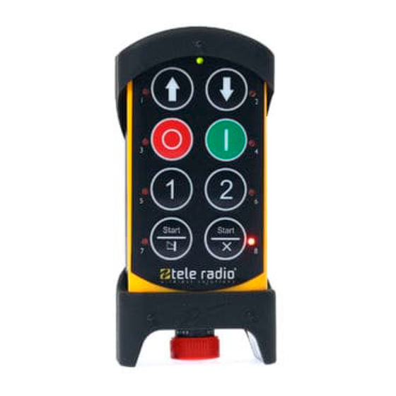
CHAPTER 5: PRODUCT GENERAL DESCRIPTION The pictures shown in this chapter are for illustrative purposes only. 5 . 1 T r a n s m i t t e r f r o n t T9-01, T9-11 T11-05, T11-15 1. Rubber 5. -
Page 20: Transmitter Back
Installation instructions│ T9/T11│ Chapter 5: Product general description 5 . 2 T r a n s m i t t e r b a c k T9-01, T9-11 T11-05, T11-15 1. Rubber cover 4. Product label 7. Charger contacts for Tele Radio holders 2. -
Page 21: Top Led
Installation instructions│ T9/T11│ Chapter 5: Product general description 5 . 3 T o p L E D The transmitter is equipped with one bi-color LED (top LED) for battery indication and radio link information. For more details, see "Chapter 6: Status and error indications"... -
Page 22: Chapter 6: Status And Error Indications
Installation instructions│ T9/T11│ Chapter 6: Status and error indications CHAPTER 6: STATUS AND ERROR INDICATIONS 6 . 1 T o p L E D s t a t u s i n d i c a t i o n The top LED lights or flashes green when the battery capacity is good and red when the battery capacity is poor. - Page 23 Installation instructions│ T9/T11│ Chapter 6: Status and error indications LED0 LED1 LED2 LED3 LED4 LED5 LED6 LED- LED- Indicates green/red Safe buttons has been ž ™ ˜ ™ ™ ™ ™ ™ ™ pressed during start- up or stop button test is required CPU2 start-up test has ž...
- Page 24 Installation instructions│ T9/T11│ Chapter 6: Status and error indications LED0 LED1 LED2 LED3 LED4 LED5 LED6 LED- LED- Indicates green/red Incompatible config-ID ˜ ™ ™ ™ ˜ ™ ™ ™ ™ between TX/RX Unexpected response ˜ ™ ™ ™ ™ ˜...
-
Page 25: Chapter 7: Operation
Installation instructions│ T9/T11│ Chapter 7: Operation CHAPTER 7: OPERATION 7 . 1 G e n e r a l i n f o r m a t i o n To control a receiver, the transmitter must be registered and logged in to the receiver. -
Page 26: Functionality Test
7 . 3 F u n c t i o n a l i t y t e s t NOTE: This list is intended for use as a support for the manufacturer of the equipment where Tele Radio remote control systems are installed. Before operating the radio system, follow the procedure below. -
Page 27: Start A Session (No Pin Code)
Installation instructions│ T9/T11│ Chapter 7: Operation 7 . 4 S t a r t a s e s s i o n ( n o P I N c o d e ) To be able to control a receiver with the transmitter, the transmitter must be registered in the receiver. - Page 28 Installation instructions│ T9/T11│ Chapter 7: Operation When a radio link has been established, the top LED stops flashing and remains lit, the selected receivers red LEDs go out and the stop relays activate. 6. Proceed with the functional test (see "7.3 ...
-
Page 29: Start A Session (Pin Code Required)
If a PIN code is required, it will be indicated as follow. T9: LEDs 1–6 flash red; T11: LEDs 1–10 flash red 3. Enter the PIN code (4 digits). Use the buttons according to the following table. Digit T9-01, T9-11 T11-05, T11-15 1–6 Buttons 1–6 Press and hold button 8 (shift) Button 7 + press button 1... - Page 30 Installation instructions│ T9/T11│ Chapter 7: Operation The receiver(s) selected in the last session are indicated by the corresponding red lit LED. Go to step 5 to log in to the previously selected receiver, go to next step to select another receiver. If no receiver is selected, the red LEDs for all available receivers will flash.
-
Page 31: Log The Transmitter Out From A Receiver
Installation instructions│ T9/T11│ Chapter 7: Operation 7 . 6 L o g t h e t r a n s m i t t e r o u t f r o m a r e c e i v e r A transmitter already logged in to the receiver has to be logged out before any other transmitter can be logged in. -
Page 32: Chapter 8: Configuration Menu
Installation instructions│ T9/T11│ Chapter 8: Configuration menu CHAPTER 8: CONFIGURATION MENU 8 . 1 M e n u m o d e a n d s t a n d a r d s e t t i n g s The Menu mode allows for certain settings to be set directly from the transmitter. -
Page 33: Enter Menu Mode
4. Press the Stop button. 5. Release the right Start button. The top LED flashes and all button LEDs representing a menu flash. 6. Select a menu by pressing the buttons according to the following table. Menu T9-01, T9-11 T11-05, T11-15 Register Button 1 Erase... -
Page 34: Show Current Radio Frequency Channel
Installation instructions│ T9/T11│ Chapter 8: Configuration menu 8 . 3 S h o w c u r r e n t r a d i o f r e q u e n c y c h a n n e l Channels are indicated by LEDs 1 and 2, which represent the first and second digit of the channel respectively. -
Page 35: Select A Radio Frequency Channel
The top LED flashes. The transmitter enters the [Switch channel] menu. 10. Enter the first digit of the new channel by pressing the buttons according to the following table. Digit T9-01, T9-11 T11-05, T11-15 1–6 Buttons 1–6 Press and hold button 8 (shift) Button 7 + press button 1... - Page 36 Installation instructions│ T9/T11│ Chapter 8: Configuration menu Digit T9-01, T9-11 T11-05, T11-15 Press and hold button 8 (shift) Button 10 + press button 4 LED 1 lights and the LED next to the left start button flashes (red). 11. Enter the second digit, or for channels 1–9 press the left Start button directly after entering the first digit.
-
Page 37: Register A Transmitter In A Receiver
Installation instructions│ T9/T11│ Chapter 8: Configuration menu 8 . 5 R e g i s t e r a t r a n s m i t t e r i n a r e c e i v e r T9 transmitters can have up to 6 registered receivers (location 1–6), T11 transmitters up to 10 (location 1–10). - Page 38 Installation instructions│ T9/T11│ Chapter 8: Configuration menu 8 . 5 . 1 R E G I S T E R T H E T R A N S M I T T E R I N A R E C E I V E R W I T H O U T D I S P L A Y ( R 4 , R 1 0 ) RISK OF UNINTENDED EQUIPMENT OPERATION Only transmitters that are intended for use should be registered in the...
- Page 39 Installation instructions│ T9/T11│ Chapter 8: Configuration menu 8. Press the left Start button to confirm. The LEDs next to both start buttons light. ON THE RECEIVER 9. Press the top button (Function button) Function LED 1 flashes (red).Red lit relay LEDs 1–7 show the number of transmitters already registered in the receiver 10.
- Page 40 Installation instructions│ T9/T11│ Chapter 8: Configuration menu 8 . 5 . 2 R E G I S T E R T H E T R A N S M I T T E R I N A R E C E I V E R W I T H D I S P L A Y ( R 9 ) RISK OF UNINTENDED EQUIPMENT OPERATION Only transmitters that are intended for use should be registered in the...
- Page 41 Installation instructions│ T9/T11│ Chapter 8: Configuration menu ON THE RECEIVER 9. Use the mini joystick to select in the receiver display menu. [Register TX] 10. Press the mini joystick to confirm. 11. Use the mini joystick to select [Yes]. Press to confirm and begin registration. The receiver will remain in registration mode until a transmitter has been registered or for up to 1 minute.
-
Page 42: Logout From Menu Mode
Installation instructions│ T9/T11│ Chapter 8: Configuration menu 8 . 6 L o g o u t f r o m M e n u m o d e This logout option is used mainly when the Quick logout button is being used by another function. -
Page 43: Erase
Installation instructions│ T9/T11│ Chapter 8: Configuration menu 8 . 7 E r a s e This procedure will erase the transmitter from the selected receiver and vice versa. NOTE: If a transmitter has been lost or seriously damaged, use the replace procedure on the transmitter. -
Page 44: Replace A Transmitter
Installation instructions│ T9/T11│ Chapter 8: Configuration menu 8 . 8 R e p l a c e a t r a n s m i t t e r It is possible to replace a registered transmitter with another transmitter of the same model. - Page 45 7. Enter the serial number (SN) of the transmitter to be replaced (i.e. the old, lost or damaged transmitter). Press the buttons according to the following table. Digit T9-01, T9-11 T11-05, T11-15 1–6 Buttons 1–6 Press and hold button 8 (shift) Button 7 + press button 1...
- Page 46 6. Press button 5 to enter the [Automatic shutdown] menu. The top LED flashes. 7. Select the automatic shutdown time by pressing a button according to the following table. Automatic shutdown T9-01, T9-11 T11-05, T11-15 time 2 minutes Button 1...
- Page 47 6. Press button 6 to enter the [Load select] menu. The top LED flashes. 7. Select the Load select by pressing a button according to the following table. Load select mode T9-01, T9-11 T11-05, T11-15 Button 1 Button 2 Button 3...
- Page 48 Installation instructions│ T9/T11│ Chapter 8: Configuration menu 8 . 1 0 . 1 L O A D S E L E C T M O D E 0 8 . 1 0 . 2 L O A D S E L E C T M O D E 1 IM-TG2-TX101-EN-v04...
- Page 49 Installation instructions│ T9/T11│ Chapter 8: Configuration menu 8 . 1 0 . 3 L O A D S E L E C T M O D E 2 8 . 1 0 . 4 L O A D S E L E C T M O D E 3 IM-TG2-TX101-EN-v04...
- Page 50 Installation instructions│ T9/T11│ Chapter 8: Configuration menu 8 . 1 0 . 5 L O A D S E L E C T M O D E 4 8 . 1 0 . 6 L O A D S E L E C T M O D E 5 IM-TG2-TX101-EN-v04...
- Page 51 Installation instructions│ T9/T11│ Chapter 8: Configuration menu 8 . 1 0 . 7 L O A D S E L E C T M O D E 6 8 . 1 0 . 8 L O A D S E L E C T M O D E 7 Load select mode 7 is set separately.
- Page 52 Installation instructions│ T9/T11│ Chapter 9: Battery CHAPTER 9: BATTERY 9 . 1 B a t t e r y p r e c a u t i o n s Carefully read the following safety instructions and warnings before using, charging or disposing of the batteries.
- Page 53 Installation instructions│ T9/T11│ Chapter 9: Battery 9 . 1 . 2 D I S P O S A L When discarding batteries, insulate the + and - terminals of batteries with insulating/ masking tape. Do not place multiple batteries in the same plastic bag. Do not incinerate or dispose of batteries in fire.
- Page 54 Installation instructions│ T9/T11│ Chapter 9: Battery 9 . 2 B a t t e r y i n f o r m a t i o n NOTE: Only batteries approved by Tele Radio should be used in T9/T11 transmitters.
- Page 55 Installation instructions│ T9/T11│ Chapter 9: Battery 9 . 2 . 1 R E M O V A L O F T H E I N T E R N A L B A T T E R Y ( T 9 ) Electronics and batteries must be physically separated before disposal.
- Page 56 Installation instructions│ T9/T11│ Chapter 9: Battery 9 . 2 . 2 C H A R G E T H E B A T T E R Y NOTE: For T9 transmitters, the 1/O switch must be in the 1/on position when charging.
- Page 57 Installation instructions│ T9/T11│ Chapter 9: Battery 3. The top LED turns green when the battery is fully charged,. Charger unit: The charger's LED turns green when the battery is fully charged. 4. Remove the charger plug and close the protection cap. For external batteries, remove the battery from the charger unit and put it back in the transmitter.
- Page 58 Installation instructions│ T9/T11│ Chapter 10: Foils CHAPTER 10: FOILS Foils are used to customized transmitters depending on the application. Tele Radio foils are made of durable, soft, flexible GO-PU/SM polyurethane film with a semi- matt surface on the front side.
- Page 59 Tele Radio products are covered by a warranty against material, construction and manufacturing faults. During the warranty period, Tele Radio may replace the product or faulty parts. Work under warranty must be performed by Tele Radio or by an authorized service center specified by Tele Radio.
- Page 60 For proper treatment, recovery and recycling, please take this product to a designated collection point. Tele Radio strives to minimize the use of hazardous materials, promotes reuse and recycling, and reduces emissions to air, soil and water. When a commercially viable alternative is available, Tele Radio strives to restrict or eliminate substances and materials that pose an environmental, health or safety risk.
- Page 61 Installation instructions│ T9/T11│ Chapter 12: Regulatory information 1 2 . 2 N o r t h A m e r i c a Applies to: T9-11, T11-15 1 2 . 2 . 1 F C C S T A T E M E N T This device complies with part 15 of the FCC Rules.
- Page 62 Installation instructions│ T9/T11│ Chapter 12: Regulatory information “Contains FCC ID: ONFC1108A” “Contains IC: 4807A-C1108A” 1 2 . 2 . 2 I C S T A T E M E N T This product complies with Industry Canada's licence-exempt RSSs. Operation is subject to the following two conditions: (1) This device may not cause interference; and (2) This device must accept any interference, including interference that may cause...
- Page 63 Installation instructions│ T9/T11│ Chapter 12: Regulatory information “Contains FCC ID: ONFC1108A” “Contains IC: 4807A-C1108A” 1 2 . 2 . 3 F C C / I C L A B E L S The radio module in this product is labeled with its own FCC ID and IC numbers. The FCC ID and IC numbers are not visible when the radio module is installed inside another device.
- Page 64 1 2 . 3 B r a z i l Applies to: T9-01, T11-05 1 2 . 3 . 1 A N A T E L S T A T E M E N T ( D E C L A R A Ç Ã O A N A T E L ) Este equipamento não tem direito à...
- Page 65 Installation instructions│ T9/T11│ Annex A: Glossary ANNEX A: GLOSSARY Diagnostic Coverage Failures in time (1 FIT = 1 failure per 10^9 hours) Hardware Fault Tolerance MTTF Mean Time To Failure Probability of Failure per Hour Performance level Safety Failure Fraction Safety Integrity Level IM-TG2-TX101-EN-v04...
- Page 66 Installation instructions│ T9/T11│ Annex B: Index ANNEX B: INDEX ANATEL Statement Automatic shutdown Battery Battery information Charge Removal of internal battery Battery precautions Handling Storage CE marking Charging temperature 16, 54 Configuration menu Dimensions Disposal Erase FCC statement FCC/IC labels Foils Frequency management Functionality test...
- Page 67 Installation instructions│ T9/T11│ Annex B: Index IC Statement Inactivity timeout IP code Load select mode Log out Logout from Menu mode Quick logout M245060 Maintenance Menu mode Enter Menu mode, no PIN code Number of channels Number of frequency banks Operating temperature Operating time Power supply...
- Page 68 Installation instructions│ T9/T11│ Annex B: Index Radio frequency output power Radio module Register Register in a receiver without display Register the transmitter in a receiver with display Register Register in R4 and R10 receivers Register Register in R9 receivers Replace Safety Features Safety levels Select a Radio frequency...
- Page 69 Installation instructions│ T9/T11│ Annex B: Index Warnings & restrictions Installation and commission Maintenance Operation WEEE directive Weight IM-TG2-TX101-EN-v04...
- Page 70 Installation instructions│ T9/T11│ This page intentionally left blank. IM-TG2-TX101-EN-v04...
- Page 71 These Installation instructions are subject to change without prior notice. Download the latest instructions from www.tele-radio.com.
Need help?
Do you have a question about the T9-01 and is the answer not in the manual?
Questions and answers