
Related Manuals for Manitou MT 1030 EASY 75D ST3B S2


Summary of Contents for Manitou MT 1030 EASY 75D ST3B S2
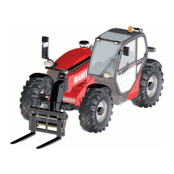
- Page 1 647480 EN (20/10/2017) MT 732 EASY 75D ST3B S1 MT 932 EASY 75D ST3B S1 MT 1030 EASY 75D ST3B S1 MT 1030 EASY 75D ST3B S2 OPERATOR'S MANUAL (ORIGINAL INSTRUCTIONS)
- Page 2 - Descriptions and figures are non binding. - MANITOU reserves the right to change its models and their equipment without being required to update this manual. - The MANITOU network, consisting exclusively of qualified professionals, is at your disposal to answer all your questions.
- Page 3 MANITOU BF. Any violation of the aforementioned may lead to civil and criminal prosecution. The logos as well as the visual identity of the company are the property of MANITOU BF and may not be...
- Page 4 1 - OPERATING AND SAFETY INSTRUCTIONS 2 - DESCRIPTION 3 - MAINTENANCE 4 - OPTIONAL ATTACHMENTS FOR USE WITH THE RANGE...
-
Page 5: Operating And Safety Instructions
1 - OPERATING AND SAFETY INSTRUCTIONS 1 - 1... - Page 6 1 - 2...
- Page 7 1 - 3...
-
Page 8: Table Of Contents
TABLE OF CONTENTS 1 - OPERATING AND SAFETY INSTRUCTIONS INSTRUCTIONS TO THE COMPANY MANAGER THE SITE THE OPERATOR THE LIFT TRUCK A - THE TRUCK'S SUITABILITY FOR THE JOB ..........6 B - ADAPTATION OF THE LIFT TRUCK TO STANDARD ENVIRONMENTAL CONDITIONS . - Page 9 LIFT TRUCK MAINTENANCE INSTRUCTIONS GENERAL INSTRUCTIONS PLACING THE JIB SAFETY WEDGE FITTING THE WEDGE............24 REMOVING THE WEDGE .
-
Page 10: Instructions To The Company Manager
A - THE TRUCK'S SUITABILITY FOR THE JOB - MANITOU has ensured that this lift truck is suitable for use under the standard operating conditions defined in this operator's manual, with a STATIC test coefficient OF 1,33 and a DYNAMIC test coefficient OF 1, as specified in harmonised standard EN 1459 for variable range trucks. -
Page 11: C - Modification Of The Lift Truck
• Adapt the seat adjustment to the operator's weight (according to lift truck model) and maintain it in good condition, as well as the cab suspension. Inflate the tires in accordance with recommendations. • Ensure that the operators adapt their operating speed to suit the conditions on site. •... -
Page 12: Instructions For The Operator
- At any time, as an operator, you must envisage, within reason, the possible risk to yourself, to others or to the lift truck itself when you use it. IMPORTANT In order to reduce or avoid any danger with a MANITOU-approved attachment, follow the instructions of paragraph: 4 - ADAPTABLE ATTACHMENTS IN OPTION ON THE RANGE: INTRODUCTION. GENERAL INSTRUCTIONS A - OPERATOR'S MANUAL - Read the operator's manual carefully. -
Page 13: E - Lifting People
• With a PLATFORM-fitted lift truck, people can only be lifted using platforms designed by MANITOU for the purpose. - MANITOU sells equipment specifically designed for lifting people (OPTION PLATFORM lift truck, contact your dealer). OPERATING INSTRUCTIONS UNLADEN AND LADEN A - BEFORE STARTING THE LIFT TRUCK - Perform the daily service (see: 3 - MAINTENANCE: A - DAILY OR EVERY 10 HOURS SERVICE). -
Page 14: D - Visibility
- Travelling on a longitudinal slope: • Drive and brake gently. • Moving without load: Forks or attachment facing downhill. • Moving with load: Forks or attachment facing uphill. - Take into account the lift truck’s dimensions and its load before trying to negotiate a narrow or low passageway. - Never move onto a loading platform without having first checked: •... -
Page 15: E - Starting The Lift Truck
E - STARTING THE LIFT TRUCK SAFETY INSTRUCTIONS IMPORTANT The lift truck must only be started up or manoeuvred when the operator is sitting in the driver’s cab, with his seat belt adjusted and fastened. - Never try to start the lift truck by pushing or towing it. Such operation may cause severe damage to the transmission. If necessary, to tow the lift truck in an emergency, the transmission must be placed in the neutral position (see: 3 - MAINTENANCE: G - OCCASIONAL MAINTENANCE). -
Page 16: G - Stopping The Lift Truck
- Do not leave the cab when the lift truck has a raised load. - Look where you are going and always make sure you have good visibility along the route. - Use the rear-view mirrors frequently. - Drive round obstacles. - Never drive on the edge of a ditch or steep slope. -
Page 17: H - Driving The Lift Truck On The Public Highway
H - DRIVING THE LIFT TRUCK ON THE PUBLIC HIGHWAY (or see current legislation in other countries) FRENCH ROAD TRAFFIC RULES - The driving of non EC type-approved tractors on the public highway is subject to the provisions of the highway code relating to special machines, defined in article R311-1 of the highway code, in category B of the Equipment Order of 20 November 1969 that determines the procedures applicable to special machines. -
Page 18: Instructions For Handling A Load
INSTRUCTIONS FOR HANDLING A LOAD A - CHOICE OF ATTACHMENTS - Only attachments approved by MANITOU can be used on its lift trucks. - Make sure the attachment is appropriate for the work to be done (see: 4 - ADAPTABLE ATTACHMENTS IN OPTION ON THE RANGE). -
Page 19: D - Transverse Attitude Of The Lift Truck
D - TRANSVERSE ATTITUDE OF THE LIFT TRUCK Depending on the model of lift truck The transverse attitude is the transverse slope of the chassis with respect to the horizontal. Raising the jib reduces the lift truck's lateral stability. The transverse attitude must be set with the jib in down position as follows: 1 - LIFT TRUCK WITHOUT ROLL CORRECTOR USED ON TYRES - Position the lift truck so that the bubble in the level is between the two lines (see: 2 - DESCRIPTION: INSTRUMENTS AND CONTROLS). -
Page 20: F - Taking Up And Laying A High Load On Tyres
F - TAKING UP AND LAYING A HIGH LOAD ON TYRES IMPORTANT You must not raise the jib if you have not checked the transverse attitude of the lift truck (see: INSTRUCTIONS FOR HANDLING A LOAD: D - TRANSVERSE ATTITUDE OF THE LIFT TRUCK). REMINDER: Make sure that the following operations can be performed with good visibility (see: OPERATIONS INSTRUCTIONS UNLADEN AND LADEN: D - VISIBILITY). - Page 21 LAYING A HIGH LOAD ON TYRES - Approach the load in the transport position in front of the stack (fig. F6). - Apply the parking brake and place the forward/reverse selector in neutral. - Raise and extend the jib (1) (2) until the load is above the stack, while monitoring the longitudinal stability limiter and warning device (see: INSTRUCTIONS FOR HANDLING A LOAD: C - LONGITUDINAL STABILITY LIMITER AND WARNING DEVICE).
-
Page 22: G - Taking Up And Laying A High Load On Stabilizers
G - TAKING UP AND LAYING A HIGH LOAD ON STABILIZERS Depending on the model of lift truck IMPORTANT You must not raise the jib if you have not checked the transverse attitude of the lift truck (see: INSTRUCTIONS FOR HANDLING A LOAD: D - TRANSVERSE ATTITUDE OF THE LIFT TRUCK). - Page 23 TAKING UP A HIGH LOAD ON STABILISERS - Ensure that the forks will easily pass under the load. - Check the position of the lift truck with respect to the load and make a test run, if necessary, without taking the load. - Raise and extend the jib (1) (2) until the forks are at the level of the load (fig.
-
Page 24: H - Taking Up And Laying Down A Suspended Load
H - TAKING UP AND LAYING DOWN A SUSPENDED LOAD IMPORTANT Failure to follow the above instructions may lead the lift truck to loose stability and overturn. MUST be used with a lift truck equipped with an operational hydraulic movement cut-out device. CONDITIONS OF USE - The length of the sling or the chain shall be as short as possible to limit swinging of the load. -
Page 25: Platform Operating Instructions
B - LIFT TRUCK SUITABILITY FOR USE - MANITOU has ensured that this platform is suitable for use under the normal operating conditions defined in this operator's manual, with a STATIC test coefficient OF 1,25 and a DYNAMIC test coefficient OF 1,1, as specified in harmonised standard EN 280 for "mobile elevating work platforms". -
Page 26: F - Maintenance
IMPORTANT It is strictly forbidden to use the platform when the wind speed exceeds 45 km/h. - To visually recognise this wind speed, refer to the empirical wind evaluation scale below: BEAUFORT scale (wind speed at a height of 10 m on a flat site) Speed Speed Speed... -
Page 27: Instructions For Using The Radio-Control
INSTRUCTIONS FOR USING THE RADIO-CONTROL For lift trucks with RC radio control HOW TO USE THE RADIO-CONTROL SAFETY INSTRUCTIONS - This radio-control consists of electronic and mechanical safety elements. It cannot receive commands from another transmitter because the internal encoding is unique to each radio-control. IMPORTANT If it is used improperly or incorrectly, there is a risk of danger to: - The physical and mental health of the user or others. - Page 28 LIFT TRUCK MAINTENANCE INSTRUCTIONS GENERAL INSTRUCTIONS - Ensure the area is sufficiently ventilated before starting the lift truck. - Wear clothes suitable for the maintenance of the lift truck, avoid wearing jewellery and loose clothes. Tie and protect your hair, if necessary. - Stop the engine and remove the ignition key, when an intervention is necessary.
- Page 29 LUBRICANT AND FUEL LEVELS - Use the recommended lubricants (never use contaminated lubricants). - Do not fill the fuel tank when the engine is running. - Only fill up the fuel tank in areas specified for this purpose. - Do not fill the fuel tank to the maximum level. - Do not smoke or approach the lift truck with a flame, when the fuel tank is open or is being filled.
- Page 30 IF THE LIFT TRUCK IS NOT TO BE USED FOR A LONG TIME INTRODUCTION The following recommendations are intended to prevent the lift truck from being damaged when it is withdrawn from service for an extended period. IMPORTANT Procedures to follow if the lift truck is not to be used for a long time and for starting it up again afterwards must be performed by your dealership. This long-term storage period must not exceed 12 months.
- Page 31 • Glass items can be removed and collected for processing by glaziers. ENVIRONMENTAL PROTECTION By entrusting the maintenance of your lift truck to the MANITOU network, the risk of pollution is limited and the contribution to environmental protection contribution is made.
- Page 32 1 - 28...
- Page 33 2 - DESCRIPTION 2 - 1...
- Page 34 2 - 2...
- Page 35 MT 732 EASY 75D ST3B S1 CHARACTERISTICS MT 932 EASY 75D ST3B S1 CHARACTERISTICS MT 1030 EASY 75D ST3B S1 CHARACTERISTICS MT 1030 EASY 75D ST3B S2 CHARACTERISTICS TIRES MT 732 EASY 75D ST3B S1 DIMENSIONS AND LOAD CHART MT 932 EASY 75D ST3B S1 DIMENSIONS AND LOAD CHART MT 1030 …...
-
Page 36: Ec" Declaration Of Conformity
The company 430, rue de l’Aubinière - BP 10249 - 44158 - ANCENIS CEDEX - FRANCE Adresse, Address MANITOU BF - 430, rue de l’Aubinière Dossier technique, Technical file BP 10249 - 44158 - ANCENIS CEDEX - FRANCE Constructeur de la machine décrite ci-après,... - Page 37 bg : 1) удостоверение за « СЕ » съответствие (oригинална), 2) Фирмата, 3) Адрес, 4) Техническо досие, 5) Фабрикант на описаната по-долу машина, 6) Обявява, че тази машина, 7) Отговаря на следните директиви и на тяхното съответствие национално право, 8) За машините към допълнение IV, 9) Номер...
-
Page 38: Safety Plates And Stickers
SAFETY PLATES AND STICKERS IMPORTANT Clean all the safety plates and stickers to make them legible. It is essential to replace safety plates and stickers which are illegible or damaged. Check the presence of safety plates and stickers after replacing any spare parts. EXTERNAL PLATES AND STICKERS ITEM PART NO. - Page 39 PLATES AND STICKERS UNDER THE ENGINE BONNET ITEM PART NO. DESCRIPTION 52501046 - Anti-freeze 259398 - Water/diesel separator 52505436 - Engine fuse N°52501046 Diagn F46 F45 Fuel pump Fuel FUEL / WATER pump SEPARATOR N°52505436 FUEL 259398 2 - 7...
- Page 40 Tests performed under intensive operationnal conditions l/hour l/ hour Handling Idle * Calculation based on a 25% idle and 75% handling cycle Kg CO2/hour Tests carried out by Manitou following the EP-695 internal procedure as approved by 2 - 8...
- Page 41 FOPS - ISO 3449 ROPS - ISO 3471 ANSI B 56.6 N 193032 BREVETS - PATENTS FR 93 14367 EP 0 656 315 US PENDING N°223324 MANITOU BF 44158 ANCENIS CEDEX FRANCE MODELE MODELLO SERIE SERIE MODEL MODELO SERIES SERIE Année de fabrication...
- Page 42 NOTE: For the owner's convenience, it is recommended that a note of these numbers is made in the spaces provided at the time of the delivery of the lift truck. LIFT TRUCK MANUFACTURER’S PLATE 1 - MODEL 2 - SERIES MANITOU BF 44158 ANCENIS CEDEX FRANCE MODELE MODELLO SERIE SERIE...
- Page 43 FRONT AXLE • Type • Serial No. • MANITOU Part no. REAR AXLE • Type • Serial No. • MANITOU Part no. • Type • Serial No. BOOM • MANITOU Part no. • Date of manufacture FRAME • Lift truck serial no.
- Page 44 CONNECTION MANFACTURER’S PLATE • Model MANITOU BF 44158 ANCENIS FRANCE MODELE / MODEL / MODELLO / TYP / MODELO • Serial no. N° série / Serial Nr / N. serie / Serienum. / N. Serie • Year of manufacture Année Fabrication / Year manufacture Anno Fabbricazione / Baujahr / Año Fabricacion...
- Page 45 2 - 13...
-
Page 46: Characteristics
CHARACTERISTICS MT 732 EASY 75D ST3B S1 I.C. ENGINE Type DEUTZ TD3,6L/313 Diesel Fuel 4 in line Number of cylinders Supercharged Suction Direct Injection system Ignition sequence 1.3.4.2 Capacity 3621 Bore and stroke 98 x 120 Compression ratio Nominal speed laden 2200 Idling speed slow unladen Max. - Page 47 HYDRAULIC CIRCUIT Hydraulic pump - Type Gear type with flow divider 1st casing 2nd casing - Capacity - Max. rating capacity unladen l/mn - Flow rate at 1600 rpm l/mn Filtration - Return μm - Suction μm Maximum service pressure - Telescoping circuit 190 / 260 - Lifting circuit...
-
Page 48: Characteristics
CHARACTERISTICS MT 932 EASY 75D ST3B S1 I.C. ENGINE Type DEUTZ TD3,6L/313 Diesel Fuel 4 in line Number of cylinders Supercharged Suction Direct Injection system Ignition sequence 1.3.4.2 Capacity 3621 Bore and stroke 98 x 120 Compression ratio Nominal speed laden 2200 Idling speed slow unladen Max. - Page 49 HYDRAULIC CIRCUIT Hydraulic pump - Type Gear type with flow divider 1st casing 2nd casing - Capacity - Max. rating capacity unladen l/mn - Flow rate at 1600 rpm l/mn Filtration - Return μm - Suction μm Maximum service pressure - Telescoping circuit 190 / 260 - Lifting circuit...
-
Page 50: Characteristics
CHARACTERISTICS MT 1030 EASY 75D ST3B S1 I.C. ENGINE Type DEUTZ TD3,6L/313 Diesel Fuel 4 in line Number of cylinders Supercharged Suction Direct Injection system Ignition sequence 1.3.4.2 Capacity 3621 Bore and stroke 98 x 120 Compression ratio Nominal speed laden 2200 Idling speed slow unladen Max. - Page 51 HYDRAULIC CIRCUIT Hydraulic pump - Type Gear type with flow divider 1st casing 2nd casing - Capacity - Max. rating capacity unladen l/mn - Flow rate at 1600 rpm l/mn Filtration - Return μm - Suction μm Maximum service pressure - Telescoping circuit 190 / 260 - Lifting circuit...
-
Page 52: Characteristics
CHARACTERISTICS MT 1030 EASY 75D ST3B S2 I.C. ENGINE Type DEUTZ TD3,6L/313 Diesel Fuel 4 in line Number of cylinders Supercharged Suction Direct Injection system Ignition sequence 1.3.4.2 Capacity 3621 Bore and stroke 98 x 120 Compression ratio Nominal speed laden... - Page 53 HYDRAULIC CIRCUIT Hydraulic pump - Type Gear type with flow divider 1st casing 2nd casing - Capacity - Max. rating capacity unladen l/mn - Flow rate at 1600 rpm l/mn Filtration - Return μm - Suction μm Maximum service pressure - Telescoping circuit 190 / 260 - Lifting circuit...
-
Page 54: Mt 732 Easy 75D St3B S1
TIRES PRESSURE TYRE LOAD (kg) MT 732 EASY 75D ST3B S1 FRONT UNLADEN FRONT LADEN REAR UNLADEN REAR LADEN (bar) 400/80-24 A325 162A8 ATG ALLIANCE 460/70R24 159A8 A580 GOODYEAR 15,5/80-24 SGI 12PR TUBELESS 460/70R24 XMCL 159A8 TUBELESS 1650 4350 1750 400/80-24 156A8 IND POWER CL MICHELIN TUBELESS... - Page 55 PRESSURE ON THE CONTACT SURFACE AREA OF THE CONTACT SURFACE PRESSURE LOAD (kg/cm2) (cm2) (bar) (kg) HARD SOIL LOOSE SOIL HARD SOIL LOOSE SOIL 1650 1700 1750 400/80-24 A325 162A8 ATG 1850 4350 1750 2150 ALLIANCE 4850 1650 1700 460/70R24 159A8 A580 1750 1850 2150...
-
Page 56: Dimensions And Load Chart Mt 1030
DIMENSIONS AND LOAD CHART MT 732 EASY 75D ST3B S1 1200 2810 1193 1128 4761 4696 4193 5961 1930 1930 1260 1715 ° ° 3685 6485 3490 2299 2488 4800 1310 3800 2340 ° ° 2 - 24... - Page 57 MT732-75 50° 60° 63° 40° 6,90 30° 20° 10° 0° -3° 0.5m 3,75 2,55 1,85 1,25 3,94 3,25 2,15 1,70 SUIVANT NORME EN 1459 annexe B. 2 - 25...
-
Page 58: Mt 932 Easy 75D St3B S1
DIMENSIONS AND LOAD CHART MT 932 EASY 75D ST3B S1 1200 2810 1128 1064 4696 4632 4193 5896 1930 1930 1260 1715 ° ° 3685 7620 3460 2299 2488 4770 1310 3800 2340 ° ° 2 - 26... - Page 59 MT932-75 50° 60° 61.5° 40° 9,07 30° 20° 10° 0° 0.5m -5° 6,35 4,40 3,45 2,25 1,20 5,75 3,95 2,65 1,75 SUIVANT NORME EN 1459 annexe B. 2 - 27...
- Page 60 DIMENSIONS AND LOAD CHART MT 1030 … 1200 2690 1513 1602 4992 5081 4050 6192 1930 1930 1260 1715 ° ° 3545 7810 3640 2299 2488 4950 1310 3752 4200 2340 2210 1132 ° 11,9 ° 113,7 2 - 28...
- Page 61 MT1030 S/MT-X1030 ST 50° 60° 61° 40° 9.64 30° 20° 10° 0° 0.5m -5° 1.56 5.15 2.34 1.60 SUIVANT NORME EN 1459 annexe B. MT1030 S/MT-X1030 ST 50° 60° 67.3° 9.98 40° 30° 20° 10° 0° -0.5 0.5m 3.35 7.15 4.45 1.52 SUIVANT NORME EN 1459 annexe B.
-
Page 62: Visibility
VISIBILITY MT 732 EASY 75D ST3B S1 Our lift trucks conform to European standard EN15830 with regard to operator visibility. - Follow the instructions for optimizing operator visibility of the immediate vicinity (see: 1 - OPERATING AND SAFETY INSTRUCTIONS: INSTRUCTIONS TO THE OPERATOR: DRIVING INSTRUCTIONS UNLADEN AND LADEN: D - VISIBILITY). - Page 63 DIRECT AND/OR INDIRECT VISIBILITY BLIND SPOT ZONES In accordance with EN15830, the two diagrams indicate blind spot zones on the visibility test circle (r 12m) and the 1m rectangular zone around the lift truck. HANDLING SUSPENDED LOADS 9,5 m 1 m3 r 12 m 45°...
-
Page 64: Mt 932 Easy 75D St3B S1
VISIBILITY MT 932 EASY 75D ST3B S1 Our lift trucks conform to European standard EN15830 with regard to operator visibility. - Follow the instructions for optimizing operator visibility of the immediate vicinity (see: 1 - OPERATING AND SAFETY INSTRUCTIONS: INSTRUCTIONS TO THE OPERATOR: DRIVING INSTRUCTIONS UNLADEN AND LADEN: D - VISIBILITY). - Page 65 DIRECT AND/OR INDIRECT VISIBILITY BLIND SPOT ZONES In accordance with EN15830, the two diagrams indicate blind spot zones on the visibility test circle (r 12m) and the 1m rectangular zone around the lift truck. HANDLING SUSPENDED LOADS 9,5 m 1 m3 r 12 m 45°...
- Page 66 VISIBILITY MT 1030 … Our lift trucks conform to European standard EN15830 with regard to operator visibility. - Follow the instructions for optimizing operator visibility of the immediate vicinity (see: 1 - OPERATING AND SAFETY INSTRUCTIONS: INSTRUCTIONS TO THE OPERATOR: DRIVING INSTRUCTIONS UNLADEN AND LADEN: D - VISIBILITY).
- Page 67 DIRECT AND/OR INDIRECT VISIBILITY BLIND SPOT ZONES In accordance with EN15830, the two diagrams indicate blind spot zones on the visibility test circle (r 12m) and the 1m rectangular zone around the lift truck. HANDLING SUSPENDED LOADS 9,5 m 1 m3 r 12 m 45°...
- Page 68 INSTRUMENTS AND CONTROLS MT 732 EASY 75D ST3B S1 MT 932 EASY 75D ST3B S1 2 - 36...
- Page 69 DESCRIPTION 1 - DRIVER'S SEAT 2 - SEAT BELT 3 - CONTROL AND SIGNAL LIGHTS PANEL 4 - LONGITUDINAL STABILITY LIMITER AND WARNING DEVICE 5 - EMERGENCY STOP BUTTON 6 - SWITCHES 7 - LIGHTING, HORN AND INDICATOR LIGHTS 8 - FRONT AND REAR WINDSCREEN WIPER SWITCH 9 - IGNITION SWITCH 10 - FUSES AND RELAYS IN THE CAB 11 - FUSES AND RELAYS UNDER THE ENGINE BONNET...
-
Page 70: Instruments And Controls
INSTRUMENTS AND CONTROLS MT 1030 EASY 75D ST3B S1 2 - 38... - Page 71 DESCRIPTION 1 - DRIVER'S SEAT 2 - SEAT BELT 3 - CONTROL AND SIGNAL LIGHTS PANEL 4 - LONGITUDINAL STABILITY LIMITER AND WARNING DEVICE 5 - EMERGENCY STOP BUTTON 6 - SWITCHES 7 - LIGHTING, HORN AND INDICATOR LIGHTS 8 - FRONT AND REAR WINDSCREEN WIPER SWITCH 9 - IGNITION SWITCH 10 - FUSES AND RELAYS IN THE CAB 11 - FUSES AND RELAYS UNDER THE ENGINE BONNET...
-
Page 72: Instruments And Controls
INSTRUMENTS AND CONTROLS MT 1030 EASY 75D ST3B S2 19 19 2 - 40... - Page 73 DESCRIPTION 1 - DRIVER'S SEAT 2 - SEAT BELT 3 - CONTROL AND SIGNAL LIGHTS PANEL 4 - LONGITUDINAL STABILITY LIMITER AND WARNING DEVICE 5 - EMERGENCY STOP BUTTON 6 - SWITCHES 7 - LIGHTING, HORN AND INDICATOR LIGHTS 8 - FRONT AND REAR WINDSCREEN WIPER SWITCH 9 - IGNITION SWITCH 10 - FUSES AND RELAYS IN THE CAB 11 - FUSES AND RELAYS UNDER THE ENGINE BONNET...
- Page 74 1 - DRIVER'S SEAT DRIVER’S SEAT (STANDARD) DESIGNED FOR MAXIMUM COMFORT, THIS SEAT CAN BE ADJUSTED AS FOLLOWS. LONGITUDINAL ADJUSTMENT - Unlock the locking lever 1. - Slide the seat to the desired position. - Release the lever and be sure it returns to the lock position. SEAT HEIGHT ADJUSTMENT - Sit down correctly in the seat.
- Page 75 DRIVER'S PNEUMATIC SEAT (OPTION) DESIGNED FOR MAXIMUM COMFORT, THIS SEAT CAN BE ADJUSTED AS FOLLOWS. SEAT HEIGHT ADJUSTMENT - Sit down correctly in the seat. - Switch on lift truck ignition. - Pull or push lever 1 according to the desired height, making sure that the green indicator lamp 2 remains visible.
- Page 76 3 - CONTROL PANEL • 3A - CONTROL PANEL • 3B - SCREEN DISPLAY 3A - CONTROL PANEL IMPORTANT A permanently lit or flashing warning lamp, with the engine running, is the sign of an operating fault. The lighting of some lamps may be accompanied by an audible signal.
- Page 77 BRAKING OIL LEVEL WARNING INDICATOR LAMP If the indicator lamp and buzzer come on, when the lift truck is running, stop the engine immediately and look for the cause (braking oil level, possible leak, etc.). In the event of an abnormal drop in the level, consult your dealer. PARKING BRAKE INDICATOR LAMP This indicator lamp comes on when the parking brake is applied.
- Page 78 3B - SCREEN DISPLAY - Turn on the lift truck ignition using the ignition key. - The initialization screen appears, please wait. - The screen appears to show: • The direction of travel (F for forward/R for reverse/N for neutral). •...
- Page 79 4 - LONGITUDINAL STABILITY LIMITER AND WARNING DEVICE IMPORTANT The operator must respect the lift truck's load chart, and the operating mode according to the attachment. This device warns the operator of the lift truck's longitudinal stability limits. However, lateral stability can reduce the load chart in the upper part, and this reduction is not detected by the device.
- Page 80 "BUCKET" MODE USE WITH BUCKET CONFIGURATION 1 - Place the lift truck in the transport position. - Press the button, "BUCKET" MODE is confirmed by an audible beep and the lighting of the indicator lamp. - Press this button again to return to "HANDLING” MODE. - Protection against forward tip-over when making aggravating movements is ensured, except when the telescopic boom is retracted.
- Page 81 “SUSPENDED LOAD" MODE USE WITH HOIST (offering a higher safety margin) - Place the lift truck in the transport position. - Press the button, the “SUSPENDED LOAD” MODE is confirmed by a beep and the lighting of the indicator lamp. Hydraulic tilting movements are disabled, as well as the lifting movement when the longitudinal stability limit is reached (indicator lamp A8 lit).
- Page 82 A - VISUAL ALARMS • A1 - A2 - A3: There is a significant reserve of longitudinal stability. • A4 - A5: The lift truck is approaching the limit of longitudinal stability, move with care. • A6: The lift truck is close to the limit for longitudinal stability. Drive carefully. •...
- Page 83 5 - EMERGENCY STOP BUTTON In the event of danger, it enables the engine to be shut down, thereby cutting-off all hydraulic movements. IMPORTANT Warning, hydraulic movements suddenly stop when using this button. If possible, stop the lift truck before using the emergency stop. - Turn the knob to deactivate it before restarting the lift truck.
- Page 84 MT 1030 … S1 - Position 1: Indicator lamp is on, transmission is cut-off with the service brake pedal and the forward/neutral/reverse gear lever. - Position 2: Indicator light is off, transmission is cut-off to the hydraulic control lever and forward/ neutral/reverse gear lever.
- Page 85 MT 1030 … S2 N - ENGINE SPEED REGULATOR See: 2 - DESCRIPTION: DESCRIPTION AND USE OF THE OPTIONS. O - ROTATING BEACON LIGHT P - OPTION FRONT AND REAR WORKING LIGHTS Q - ATTACHMENT HYDRAULIC LOCKING OPTION See: 2 - DESCRIPTION: DESCRIPTION AND USE OF THE OPTIONS. R - NEUTRALIZATION OF HYDRAULIC MOVEMENTS When driving on the road, it is highly recommended (mandatory in Germany) that you cut-off all the hydraulic movements.
- Page 86 10 - FUSES AND RELAYS IN THE CAB A sticker on the inside of the access panel provides a quick indication of the use of the fuse plate's components described below. - Remove access panel 1 to gain access to the fuses and relays, Replace a used fuse with a new fuse of the same quality and capacity.
- Page 87 • F29 - Hazard warning lights (15A). Roof light (15A). Anti-theft device predisposition (15A). Clock (15A). Rev. counter (15A). • F30 - Lights, horn and indicator lights switch (25A). • F31 - Starter relay (5A). • F32 - Diagnostic plug (5A). Hydraulic movement control unit (5A).
- Page 88 12 - DIAGNOSTIC PLUG 13 - ACCELERATOR PEDAL 14 - SERVICE BRAKE PEDAL AND TRANSMISSION CUT-OFF The pedal acts on the front and rear wheels via a power assisted hydraulic braking system that slows the lift truck and brings it to a halt. Depending on the position of the transmission cut-off switch, it enables the transmission to be cut off during the free travel (see: 2 - DESCRIPTION: 6 - SWITCHES).
- Page 89 17 - FORWARD/NEUTRAL/REVERSE GEAR SELECTION When changing the direction of travel, the lift truck should be traveling at slow speed and not accelerating. • FORWARD: Push the switch forward (position A). • REVERSE: Pull the switch backward (position B). Reversing lights and a reversing sound alarm indicate that the lift truck is running in reverse.
- Page 90 19 - HYDRAULIC CONTROLS IMPORTANT Do not attempt to alter the hydraulic system pressure. In the event of malfunction, contact your dealer. ANY ALTERATION MAY RENDER THE WARRANTY NULL AND VOID. Operate the hydraulic controls gently and smoothly to avoid accidents caused by jerking of the lift truck. NOTE: If necessary, operate the steering to reset the hydraulic control steering accumulator.
- Page 91 OPTIONAL ATTACHMENT - Lift lever 1 and move it to the left or right. TRANSMISSION CUT-OFF - Button F (see: 2 - DESCRIPTION: 6 - SWITCH PANEL). FORWARD/REVERSE SELECTOR - Switch G (see 2 - DESCRIPTION: 17 - FORWARD/NEUTRAL/REVERSE GEAR SELECTOR). MT 1030 …...
- Page 92 22 - HEATER CONTROL A - FAN CONTROL This 3-speed control allows the air to be ventilated through the air vents. B - TEMPERATURE CONTROL Adjusts the temperature inside the cab. • B1 - The fan pumps in the air at ambient temperature. •...
- Page 93 24 - CAB VENTILATION FILTER See: 3 - MAINTENANCE: D - EVERY 500 HOURS SERVICE. 25 - WINDSCREEN DEMISTER VENTS For optimum effectiveness, close the heating ventilators. 26 - HEATING VENTS These swiveling heating vents, which can be shut off, allow you to direct and adjust the flow inside the cab. 27 - BRAKING OIL AND WINDSCREEN WASHER TANK ACCESS PANEL - Loosen screw 1 and lift up the braking oil and windscreen washer tank access panel (see: 3 - MAINTENANCE: B - EVERY 50 HOURS OF SERVICE).
- Page 94 33 - SUN VISOR (OPTION) 34 - ROOF LIGHT (OPTION) 35 - HOOK MT 732/932 … - MT 1030 …S2 36 - CIGARETTE LIGHTER For 12 V appliance and max. amperage 10A. MT 732/932 … MT 1030 … S2 MT 732/932 … 37 - ARMREST AND STORAGE Lift the armrest to access the storage.
- Page 95 40 - FRONT HEADLIGHTS • A - Left front indicator. • B - Left front dipped beam headlight. • C - Left front main beam headlight. • D - Left front sidelight. • E - Right front indicator. • F - Right front dipped beam headlight. •...
-
Page 96: Towing Pin And Hook
TOWING PIN AND HOOK IMPORTANT Do not tow a trailer or an attachment that is not in perfect working order. Using a trailer that is not in good condition may affect the steering and braking of the lift truck and therefore the safety of the whole unit. If a third party helps in coupling or uncoupling the trailer, this person must remain visible to the driver at all times and must wait until the lift truck has stopped, the handbrake is on and the engine is switched off before performing the operation. - Page 97 MT 1030 … 4 - TRAILER BRAKE SYSTEM (OPTIONAL) - Connect the brake hose to the provided brake unit 1 on the lift truck. - Make sure the trailer brakes are working properly and test the effects of braking before taking the trailer onto the public highway. 2 - 65...
-
Page 98: Description And Use Of The Options
DESCRIPTION AND USE OF THE OPTIONS 1 - MODCOD ANTI-THEFT SYSTEM 2 - MODCLE ANTI-START SYSTEM 3 - ATTACHMENT CIRCUIT WITH QUICK-RELEASE COUPLERS MT 732/932 … - MT 1030 … S2 4 - ENGINE SPEED REGULATOR MT 732/932 … - MT 1030 … S2 5 - ATTACHMENT HYDRAULIC CONTROL FORCED OPERATION MT 732/932 …... - Page 99 MT 732/932 … - MT 1030 … S2 5 - ATTACHMENT HYDRAULIC CONTROL FORCED OPERATION IMPORTANT This OPTION must only be used with an attachment requiring continuous hydraulic movement, such as a brush, feeder bucket, mixer, spray etc. It is strictly forbidden for use in handling operations and all other applications (winch, crane jib, crane jib with winch, hook, etc.).
- Page 100 8 - BOOM ELECTRICAL PREDISPOSITION Enables an electrical function to be used at the telescope head. NOTE: Setting switch 1 to position A (indicator lamp off ) controls the hydraulic attachment line (see: 2 - DESCRIPTION: 19 - HYDRAULIC AND TRANSMISSION CUT-OFF CONTROLS). MT 732/932 …...
- Page 101 MT 1030 … S1 ATTACHMENT LINE L1 CONTROL - Set switch 2 to position A (indicator lamp off). - Lift and move lever 3 to the left or right. ATTACHMENT LINE L2 CONTROL - Set switch 2 to position B (indicator lamp on). - Hold down button 4 and move lever 3 to the left or right.
- Page 102 11 - TELESCOPE HEAD ELECTROVALVE + HYDRAULIC ATTACHMENT LOCKING The addition of these two options on the attachment line allows two hydraulic functions to be used and locks the attachment onto the carriage. IMPORTANT For ease of connection of the quick-release couplers, decompress the hydraulic circuit by pressing button 1 on the electrovalve.
- Page 103 12 - EXTERIOR DRAIN-BACK Enables connection of a hydraulic attachment for which drain-back is required. 13 - LIFTING RING ON SINGLE CARRIAGE CONDITIONS OF USE IMPORTANT Follow the instructions given in the instruction manual (see: 1 - OPERATING AND SAFETY INSTRUCTIONS: INSTRUCTIONS FOR HANDLING LOADS). - The lifting ring must be used WITHOUT FORKS AND ATTACHMENTS, but the angle of inclination of the carriage must be same as when the forks are used in the horizontal...
- Page 104 15 - SINGLE SIDE-SHIFT CARRIAGE (TSDL) TSDL MT 1030 … S1 IMPORTANT The single side-shift carriage (TSDL) is only compatible with the following attachments: • floating fork carriage (TFF) • tilting fork carriage (PFB) • loading bucket (CBR) • concrete bucket (BB, BBG) •...
- Page 105 3 - MAINTENANCE 3 - 1...
- Page 106 3 - 2...
- Page 107 TABLE OF CONTENTS 3 - MAINTENANCE ORIGINAL MANITOU SPARE PARTS AND EQUIPMENT FILTERS CARTRIDGES AND BELTS LUBRICANTS AND FUEL SERVICING SCHEDULE A - DAILY OR EVERY 10 HOURS OF SERVICE B - EVERY 50 HOURS SERVICE C - EVERY 250 HOURS OF SERVICE...
-
Page 108: Original Manitou Spare Parts And Equipment
• Efficient help with diagnosis. • Improvements due to experience feedback. • Operator training. • Only the MANITOU network has detailed knowledge of the design of the lift truck and therefore the best technical ability to provide maintenance. IMPORTANT ORIGINAL REPLACEMENT PARTS ARE DISTRIBUTED EXCLUSIVELY BY MANITOU AND ITS DEALER NETWORK. -
Page 109: Filters Cartridges And Belts
FILTERS CARTRIDGES AND BELTS ENGINE ENGINE OIL FILTER ALTERNATOR BELT Part number: 799966 Part number: 941243 Change: 500 H Change: 1000 H DRY AIR FILTER CARTRIDGE COMPRESSOR BELT Part number: 563416 (AIR CONDITIONING OPTION) Clean: 50 H Part number: 319790 Change: 1000 H Change: 3000 H SAFETY DRY AIR FILTER CARTRIDGE... -
Page 110: Lubricants And Fuel
USE THE RECOMMENDED LUBRICANTS AND FUEL: - For topping up, oils may not be miscible. - For oil changes, MANITOU oils are perfectly appropriate. DIAGNOSTIC ANALYSIS OF OILS If a service or maintenance contract has been organized with the dealer, a diagnostic analysis of engine, transmission and axle oils may be requested depending on the rate of use. - Page 111 STABILISERS PACKAGING PACKAGING / PART NUMBER PRODUCT 1 LITRE 2 LITRES 5 LITRES 20 LITRES 55 LITRES 209 LITRES - MANITOU OIL EVOLOGY 10W40 API CJ4 895837 895838 895839 895840 - MANITOU OIL AUTOMATIC TRANSMISSION DX IIIG 958186 947972 947973...
-
Page 112: Servicing Schedule
SERVICING SCHEDULE IMPORTANT (1): MANDATORY 500 HOUR OR 6 MONTH SERVICE. This service must be carried out after approximately the first 500 hours of operation or within the 6 months following the start-up of the machine (whichever occurs first). (2): Every 10 hours during the first 50 hours then a final time at 250 hours. (3): Contact your dealer. - Page 113 A = ADJUST, C = CHECK, G = GREASE, N = CLEAN, PAGE P = BLEED, R = REPLACE, V = DRAIN C (3) - Condition of cylinders (leakage, shafts) C (3) - Hydraulic circuit pressures BRAKE 3-17 - Brake oil level 3-20 - Parking brake 3-24...
-
Page 114: A - Daily Or Every 10 Hours Of Service
A - DAILY OR EVERY 10 HOURS OF SERVICE A1 – ENGINE OIL LEVEL CHECK Place the lift truck on level ground with the engine stopped, and let the oil drain into the sump. - Open the engine bonnet. - Pull out dipstick 1. - Clean the dipstick and check the correct level between the two notches. - Page 115 To be carried out every 10 hours during the first 50 hours service, then once at 250 hours. IMPORTANT If the lift truck is used in an abrasive environment (dust, sand, coal) Use lubricating varnish (MANITOU part no.: 483536). Please consult your dealer. Fully extend the boom.
- Page 116 A7 – LONGITUDINAL STABILITY LIMITER AND WARNING DEVICE CHECK IMPORTANT Use the test button only when requested to do so, applying short presses (less than 1 second) and long presses (5 seconds) as instructed. If in doubt during the test procedure, exit cleanly by short pressing the "BUCKET" or "SUSPENDED LOAD"...
- Page 117 3 - 13...
-
Page 118: B - Every 50 Hours Service
30 mm from the cartridge wall. - Cleaning is completed when there is no more dust on the cartridge. - Clean the cartridge seal surfaces with a damp, clean lint-free cloth and grease with a silicone lubricant (MANITOU reference: 479292). - Page 119 B3 – GEAR BOX OIL LEVEL CHECK Park the lift truck on level ground with the boom raised, the engine shut down. Carry out the check within 5 minutes of engine shutdown. IMPORTANT Raise the boom and place the boom safety wedge on the rod of the lifting cylinder (see: 1 - OPERATING AND SAFETY INSTRUCTIONS: LIFT TRUCK MAINTENANCE INSTRUCTIONS).
- Page 120 B5 – GENERAL GREASING GREASE To be carried out weekly, if the lift truck has been operated for less than 50 hours during the week. IMPORTANT In the event of prolonged use in an extremely dusty or oxidizing atmosphere, reduce this interval to every 10 hours of service or every day. Clean and lubricate the following points with grease (see: 3 - MAINTENANCE: LUBRICANTS AND FUEL) and remove the surplus of grease.
- Page 121 B6 – HYDRAULIC OIL LEVEL CHECK Place the lift truck on level ground with the engine stopped, and the boom retracted and lowered as far as possible. IMPORTANT Use a clean funnel and clean the underside of the oil drum before filling. - Check dipstick 1, the correct level must stand at the level of the red point.
- Page 122 B9 – CAB VENTILATION FILTER (AIR CONDITIONING OPTION) CLEAN - Unscrew thumbscrew 1 and remove protective casing 2. - Lift out cab ventilation filter 3. - Clean the filter with a compressed air jet. - Check its condition and change if necessary (see: 3 - MAINTENANCE: FILTERS CARTRIDGES AND BELTS).
- Page 123 3 - 19...
-
Page 124: C - Every 250 Hours Of Service
C - EVERY 250 HOURS OF SERVICE Carry out the operations described previously as well as the following operations. C1 – ANGLE GEAR BOX OIL LEVEL CHECK Park the lift truck on level ground with the boom raised and the engine stopped. IMPORTANT Raise the boom and place the boom safety wedge on the rod of the lifting cylinder (see: 1 - OPERATING AND SAFETY INSTRUCTIONS: LIFT TRUCK MAINTENANCE INSTRUCTIONS). - Page 125 C4 – HEATING BLOCK ONE WAY VALVE CLEAN - Since one way valve 1 is located under the cab, it is possible for it to become obstructed with spattered mud for example. Clean if necessary. C5 – FRONT AND REAR AXLE DIFFERENTIAL OIL LEVEL CHECK Place the lift truck on level ground with the engine stopped.
-
Page 126: D - Every 500 Hours Of Service Or Every Year
D - EVERY 500 HOURS OF SERVICE OR EVERY YEAR Carry out the operations described previously as well as the following operations. D1 – ENGINE OIL DRAIN D2 – ENGINE OIL FILTER CHANGE Place the lift truck on level ground, let the engine run at idle for a few minutes, then stop the engine. IMPORTANT Dispose of the waste oil in an ecological manner. - Page 127 D3 – DALTERNATOR/FAN/CRANKSHAFT BELT TENSION CHECK - ADJUST IMPORTANT If the belt has to be changed, check the tension again after the first 20 hours of operation. - Open the engine bonnet. - Remove the protective casing 1. - Check the belt for signs of wear and cracks and change if necessary (see: 3 - MAINTENANCE: FILTERS CARTRIDGES AND BELTS).
- Page 128 D6 – HYDRAULIC OIL CHECK MANITOU recommends analyzing the hydraulic oil after the first 500 hours of lift truck operation. Following that, MANITOU requests that the oil is analyzed every 500 hours of operation. The results will determine whether or not the hydraulic oil is changed (contact your dealer).
- Page 129 D8 – CAB VENTILATION FILTER CLEAN - Unscrew thumbscrew 1 and remove protective casing 2. - Lift out cab ventilation filter 3. - Clean the filter with a compressed air jet. - Check its condition and change if necessary (see: 3 - MAINTENANCE: FILTERS CARTRIDGES AND BELTS).
-
Page 130: E - Every 1000 Hours Of Service Or Every Two Years
E - EVERY 1000 HOURS OF SERVICE OR EVERY TWO YEARS Carry out the operations described previously as well as the following operations. E1 – DRY AIR FILTER CARTRIDGE CHANGE In case of use in a heavily dust laden atmosphere, there are pre-filtration cartridges, see: 3 - MAINTENANCE: FILTERS CARTRIDGES AND BELTS. - Page 131 E3 – FUEL FILTER CHANGE IMPORTANT Carefully clean the outside of the filter and its holder, to prevent dust from getting into the system. - Unscrew and discard the fuel filter 1. - Clean the inside of the filter head using a brush immersed in clean diesel oil. - Refit a filter and a new seal lubricated with clean diesel beforehand (see: 3 - MAINTENANCE: FILTERS CARTRIDGES AND BELTS).
- Page 132 E7 – GEAR BOX OIL DRAIN E8 – GEAR BOX SUMP STRAINER CLEAN Place the lift truck on level ground with the engine stopped, the gear box oil still warm. IMPORTANT Raise the boom and place the boom safety wedge on the rod of the lifting cylinder (see: 1 - OPERATING AND SAFETY INSTRUCTIONS: LIFT TRUCK MAINTENANCE INSTRUCTIONS).
- Page 133 E9 – ANGLE GEAR BOX OIL DRAIN Place the lift truck on level ground with the engine stopped, the angle gear box oil still warm. IMPORTANT Raise the boom and place the boom safety wedge on the rod of the lifting cylinder (see: 1 - OPERATING AND SAFETY INSTRUCTIONS: LIFT TRUCK MAINTENANCE INSTRUCTIONS).
-
Page 134: F - Every 2000 Hours Of Service Or Every Two Years
F - EVERY 2000 HOURS OF SERVICE OR EVERY TWO YEARS Carry out the operations described previously as well as the following operations. F1 – COOLING LIQUID DRAIN These operations are to be carried out when needed or once every two years at the beginning of winter. - Page 135 F2 – SAFETY DRY AIR FILTER CARTRIDGE REPLACE - For the disassembly and reassembly of the dry air filter cartridge, see: 3 - MAINTENANCE: E1 - AIR FILTER CARTRIDGE. - Gently remove the dry air filter safety cartridge 1, taking care to avoid spilling the dust. - Clean the gasket surface on the filter with a damp, clean lint-free cloth.
- Page 136 REPLACING THE DISTRIBUTOR CONTROL HEAD FILTER MT 732/932 … - MT 1030 … S2 IMPORTANT Be careful to mount the filter 6 in the same direction as the arrow. - Remove the half clamp 4. - Undo the two couplings 5 and replace the filter 6. - Refit half clamp 4.
- Page 137 3 - 33...
-
Page 138: G - Occasional Maintenance
G - OCCASIONAL MAINTENANCE G1 – WHEEL CHANGE For this operation, we advise you to use the MANITOU hydraulic jack, part no. 505507 and the MANITOU safety support, part no. 554772. IMPORTANT In the event of a wheel being changed on the public highway, secure the lift truck vicinity: - Stop the lift truck, if possible on firm, level ground. - Page 139 G2 – LONGITUDINAL STABILITY LIMITER AND WARNING DEVICE RESET According to the use of the lift truck, the device may require to be periodically reset. This procedure allows this operation to be easily done. - Provide a fork carrier or a bucket and a load corresponding to at least half the lift truck's rated capacity. - Preferably perform the reset when the lift truck is still cold (before it is used) or ensure that the temperature of the rear axle is not more than 50°C.
- Page 140 G3 – FRONT HEADLIGHTS ADJUST RECOMMENDED SETTING (as per standard ECE-76/756 76/761 ECE20) h2 = h1 - (l x 2 / 100) Adjustment of -2 % of the dipped beam relative to the horizontal axis of the headlight. ADJUSTMENT PROCEDURE - Place the unladen lift truck in the transport position and perpendicular to a white wall on flat, level ground.
- Page 141 G6 – LIFT TRUCK SLINGING - Take into account the position of the lift truck center of gravity for lifting. A = 1450 mm B = 1360 mm MT 732 … A = 1455 mm B = 1355 mm MT 932 … A = 1210 mm B = 1480 mm MT 1030 …...
- Page 142 G7 – LIFT TRUCK ON A PLATFORM TRANSPORTING IMPORTANT Ensure that the safety instructions associated with the platform are complied with before loading the lift truck and that the driver of the carrier vehicle is informed of the dimensions and the ground of the lift truck (see: 2 - DESCRIPTION: CHARACTERISTICS).
- Page 143 4 - O P T I O N A L ATTACHMENTS FOR USE WITH THE RANGE 4 - 1...
- Page 144 4 - 2...
- Page 145 TABLE OF CONTENTS 4 - OPTIONAL ATTACHMENTS FOR USE WITH THE RANGE INTRODUCTION PICKING UP THE ATTACHMENTS TECHNICAL SPECIFICATIONS OF ATTACHMENTS ATTACHMENT SHIELDS 4 - 3...
- Page 146 4 - 4...
- Page 147 MANITOU. IMPORTANT Only attachments approved by MANITOU are to be used on our lift trucks (see: 4 - ADAPTABLE ATTACHMENTS IN OPTION ON THE RANGE: TECHNICAL SPECIFICATIONS OF ATTACHMENTS). The manufacturer’s liability will be denied in case of modification or of attachment adaptation carried out without his knowing it.
- Page 148 PICKING UP THE ATTACHMENTS 1 - ATTACHMENT WITHOUT HYDRAULICS AND HAND LOCKING DEVICE TAKING UP AN ATTACHMENT - Ensure that the attachment is in a position facilitating the locking to the carriage. If it is not correctly oriented, take the necessary precautions in order to move it safely. - Check that the locking pin and the clip are in position in the bracket (fig.
- Page 149 2 - HYDRAULIC ATTACHMENT AND MANUAL LOCKING DEVICE TAKING UP AN ATTACHMENT - Ensure that the attachment is in a position facilitating the locking to the carriage. If it is not correctly oriented, take the necessary precautions in order to move it safely. - Check that the locking pin and the clip are in position in the bracket (fig.
- Page 150 TECHNICAL SPECIFICATIONS OF ATTACHMENTS FLOATING FORK CARRIAGE TFF 35 MT-1040 TFF 35 MT-1300 PART NUMBER 654093 654094 Rated capacity 3500 kg 3500 kg Width 1040 mm 1300 mm Weight 300 kg 340 kg FLOATING FORK SIDE-SHIFT CARRIAGE TFF 35 MT-1040 DL TFF 35 MT-1300 DL PART NUMBER 751543...
- Page 151 STANDARDISED TILTING FORK CARRIAGE PFB 35 N MT-1260 S2 PFB 35 N MT-1470 S2 PFB 35 N MT-1580 S2 PART NUMBER 653744 653745 653746 Rated capacity 3500 kg 3500 kg 3500 kg Width 1260 mm 1470 mm 1580 mm Weight 95 kg 120 kg 125 kg...
- Page 152 BUILDING BUCKET CBC 800 L2250 CBC 900 L2450 PART NUMBER 654471 654470 Rated capacity 814 l 893 l Width 2250 mm 2450 mm Weight 366 kg 391 kg LOADING BUCKET CBR 900 L2250 CBR 1000 L2450 PART No. 653749 654716 Rated capacity 904 l 990 l...
- Page 153 CONCRETE BUCKET (ADAPTABLE ON FORKS) BB 500 S4 BBH 500 S4 PART NUMBER 654409 751462 Rated capacity 500 l/1300 kg 500 l/1300 kg Width 1100 mm 1100 mm Weight 205 kg 220 kg CONCRETE BUCKET WITH SPOUT (ADAPTABLE ON FORKS) BBG 500 S4 BBHG 500 S4 PART NUMBER...
- Page 154 BOOM CRANE P 600 MT S3 REFERENCE 653228 Rated capacity 600 kg Weight 170 kg BOOM CRANE P 4000 MT S2 REFERENCE 653226 Rated capacity 4000 kg/1200 kg Weight 210 kg CRANE JIB WITH WINCH PT 600 MT S6 REFERENCE 708538 Rated capacity 600 kg...
- Page 155 BOOM CRANE JE 6000/600 REFERENCE 939995 Rated capacity 600 kg Weight 182 kg BOOM CRANE WITH BIG BAG HBB 1500/2400 REFERENCE 931627 Rated capacity 2400 kg Weight 186 kg 4 - 13...
- Page 156 ATTACHMENT SHIELDS FORK PROTECTOR PART NUMBER 227801 FORK BLOCK FOR FLOATING FORK CARRIAGE PART NUMBER 261210 BUCKET PROTECTOR Always ensure that the width of the protector you choose is less than or equal to the width of the bucket. PART NUMBER 206734 206732 206730...
Need help?
Do you have a question about the MT 1030 EASY 75D ST3B S2 and is the answer not in the manual?
Questions and answers