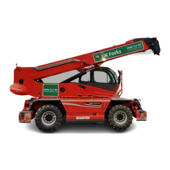
Summary of Contents for Manitou MRT Series
- Page 1 Quick Reference guide for Manitou ST3 Rotational Telehandler 21.50, 24.50 non add Blue Contact Paul Orange – 07711 957985 (North) Chris Moisey - 07711 957974 (South)
- Page 2 HANDOVER GUIDE...
- Page 3 HANDOVER GUIDE The MRT + PRIVILEGE telehandler can work with a comprehensive range of attachments, combining lift, offset and rotation functions within the same machine, and enabling the use of the machine in static mode with stabilisers. The range meets fully all the challenges with working at great heights in cramped sites.
-
Page 4: Dimensions And Weights
MRT /MRT-X PRIVILEGE Dimensions anD weighTs 1850+ 2150+ 2540+ MRT-X 2150+ 2540+ 1200 MRT 1850 + MRT 2150 + MRT 2540 + 1320 MRT-X 2150 + MRT-X 2540 + Machine weight with standard attachment (transport position): 5770 6490 7530 5050 Unladen weight 15 350 kg 16 410 kg... - Page 5 METHODOLOGY The main sTages in The hanDoVeR PRoCess LefT siDe Fuel tank and its access cover Hydraulic oil tank and its access cover (different from the hydraulic oil access cover) Hydraulic oil filling access ReaR Air conditioning radiator located under the roof cap Steering cylinder inside and above the axle Rear axle locking...
- Page 6 engine ComPaRTmenT – RighT siDe Engine oil filler port Oil filter Coolant level Air filter under the cover Battery Engine oil Fuel pre-filter level and filter fRonT Quick coupler (manual locking bolt or hydraulic locking *) Attachments (if required) Safety sleeve (to lock the lifting cylinder) Tilting corrector Telescopic stabilisers...
- Page 7 METHODOLOGY JoysTiCks Control wheel for attachment Speed control validation hydraulic line movements button (use F4 screen) Warning! This switch cuts the attachment Attachment movement selector line movements off Switch: FORWARD GEAR REVERSE GEAR NEUTRAL Check that the machine is in neutral before starting the engine Press the dead man’s button to validate the movement command...
- Page 8 FOCUS Cabine Cabin Dashboard Switch panel (overhead right) Joysticks Turret locking lever: must be on when Load charts transporting the machine or in travel mode Emergency box Heating and air conditioning* Platform emergency key: it allows another operator, in the event of impairment of the platform occupant, to start the engine and operate functions from the cabin, TURN THE KEY AND PRESS THE RED BUTTON (...
-
Page 9: Dashboard Display
FOCUS DashboaRD DisPLay Axle alignment and steering mode indications Turret alignment indication. When the icon is displayed, the turret can be locked using the lever located to the right of the seat. When the turret is aligned, the turret alignment icon is on: Load level indication Red: maximum load allowed in the current position... - Page 10 Working zone limits: the yellow icons indicate that the zone limit has been reached. The configuration is carried out by setting the machine in the required maximum position and pressing F6 to F10 keys Retrieval of speeds from memory as percentage of the boom hydraulic speed Display of attachment recognition by machine...
- Page 11 FOCUS DashboaRD Site speed (low gear) / travel speed (high gear) switch Reset switch: if required, Stabiliser it synchronises gear change movement control indicators The stabiliser movement Manual-mode parking brake selector switch (the machine is equipped as standard with automatic parking brake) Steering mode selector switch: 4 STEERING WHEELS...
- Page 12 FOCUS Emergency pump electric switch (including Electric accelerator Automatic machine Frame levelling in the platform switch levelling* control level provision) Radio-control Economy Boom suspension* switch consumption mode The machine has two speeds: Site speed (low gear) Travel speed (high gear) To select a gear: Select neutral Press fully on the brake...
- Page 13 FOCUS FOCUS Using The sTabiLiseRs Pads fully on the ground Stabiliser fully deployed Select one or several stabilisers Using switch S, select S1 or S2 mode (raise/lower or extend/retract stabilisers) Using switch Q, drive the stabilisers as per the required mode and movement: - Q1 : lower / raise stabilisers - Q 2 : extend /retract stabilisers fRame LeVeLLing...
- Page 14 Tilt the coupler Extend the boom Engage the coupler Insert the locking bolt into the coupler If it is a hydraulic attachment: connect the hoses and the return to the tank if required (e.g. winch) Attachments are now equipped with a RFID chip that enables the machine to recognize them.
-
Page 15: Radio-Control Mode
RaDio-ConTRoL moDe To change to radio-control mode: 1. Start the machine 2. Stabilise the machine 3. Press the radio-control button The engine stops Check that the door is properly closed and the gear lever is in neutral 4. Switch the radio-control on ( 5. -
Page 16: Platform Mode
PLaTfoRm moDe To change to platform mode: Hang the platform to the machine coupler; insert the locking bolt into the coupler Stabilise the machine and do not switch the ignition Connect the platform’s electrical lead to the boom head ( ). - Page 17 Ensure the correct application of all the recommendations and instructions concerning the machine that are described in the Instruction Manual. This document does not substitute in any way the Instruction Manual. www.manitou.com HG004EN_A_0413_MRTPRIV...


Need help?
Do you have a question about the MRT Series and is the answer not in the manual?
Questions and answers