
Related Manuals for Manitou ME 418 48V S3


Summary of Contents for Manitou ME 418 48V S3
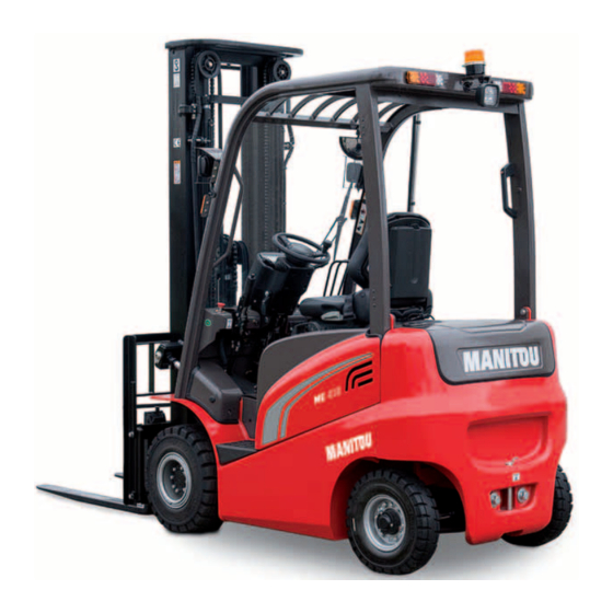
- Page 1 647503 EN (10/05/2017) ME 418 48V S3 ME 420 48V S3 ME 425 C 48V S3 OPERATOR'S MANUAL (ORIGINAL INSTRUCTIONS)
- Page 2 - Descriptions and figures are non binding. - MANITOU reserves the right to change its models and their equipment without being required to update this manual. - The MANITOU network, consisting exclusively of qualified professionals, is at your disposal to answer all your questions.
- Page 3 MANITOU BF. Any violation of the aforementioned may lead to civil and criminal prosecution. The logos as well as the visual identity of the company are the property of MANITOU BF and may not be...
- Page 4 1 - OPERATING AND SAFETY INSTRUCTIONS 2 - DESCRIPTION 3 - MAINTENANCE 4 - OPTIONAL ATTACHMENTS FOR USE WITH THE RANGE...
-
Page 5: Operating And Safety Instructions
1 - O P E R A T I N G A N D S A F E T Y INSTRUCTIONS 1 - 1... -
Page 6: Table Of Contents
TABLE OF CONTENTS 1 - OPERATING AND SAFETY INSTRUCTIONS INSTRUCTIONS TO THE COMPANY MANAGER THE SITE THE OPERATOR THE LIFT TRUCK A - THE TRUCK'S SUITABILITY FOR THE JOB ..........4 B - ADAPTATION OF THE LIFT TRUCK TO STANDARD ENVIRONMENTAL CONDITIONS . - Page 7 IF THE LIFT TRUCK IS NOT TO BE USED FOR A LONG TIME INTRODUCTION PREPARING THE LIFT TRUCK PROTECTING THE LIFT TRUCK BRINGING THE LIFT TRUCK BACK INTO SERVICE LIFT TRUCK DISPOSAL RECYCLING OF MATERIALS METALS..............17 PLASTICS.
-
Page 8: Instructions To The Company Manager
A - THE TRUCK'S SUITABILITY FOR THE JOB - MANITOU has ensured that this lift truck is suitable for use under the standard operating conditions defined in this operator's manual, with a STATIC TEST COEFFICIENT 1.33 and a DYNAMIC TEST COEFFICIENT OF 1, as specified in harmonized norm EN 1726-1 for mast trucks. -
Page 9: C - Modification Of The Lift Truck
- The following are some tips for minimizing these vibration doses: • Select the most suitable lift truck and attachment for the intended use. • Adapt the seat adjustment to the operator's weight (according to lift truck model) and maintain it in good condition, as well as the cab suspension. -
Page 10: Instructions For The Operator
Failure to respect the safety and operating instructions, or instructions for repairing or servicing your lift truck, may lead to serious, even fatal accident. In order to reduce or avoid any danger with a MANITOU-approved attachment, follow the instructions of paragraph: 4 - ADAPTABLE ATTACHMENTS IN OPTION ON THE RANGE: INTRODUCTION. -
Page 11: Operating Instructions Unladen And Laden
OPERATING INSTRUCTIONS UNLADEN AND LADEN A - BEFORE STARTING THE LIFT TRUCK - Carry out daily maintenance (see: 3 - MAINTENANCE: MAINTENANCE SCHEDULE). - Make sure that the driver's cab is clean, particularly the floor and floor mat. Check that no movable object may hinder the operation of the lift truck. -
Page 12: D - Visibility
- Never stack loads on uneven ground, they may tip over. - The load or the attachment must not be left just above a structure for long periods at a time because of the descending mast. In such a case, a constant watch must be kept and the height of the forks or the attachment readjusted if necessary. - When working near aerial lines, ensure that the safety distance is sufficient between the working area of the lift truck and the aerial line. -
Page 13: F - Driving The Lift Truck
F - DRIVING THE LIFT TRUCK SAFETY INSTRUCTIONS IMPORTANT Operators' attention is drawn to the risks involved in using the lift truck, in particular: - Risk of losing control. - Risk of losing lateral and frontal stability of the lift truck. The operator must remain in control of the lift truck. -
Page 14: G - Stopping The Lift Truck
G - STOPPING THE LIFT TRUCK SAFETY INSTRUCTIONS - Never leave the ignition key in the lift truck during the operator's absence. - When the lift truck is stationary, or if the operator has to leave his cab (even for a moment), place the forks or attachment on the ground, apply the parking brake and place the forward/reverse selector in neutral. -
Page 15: Instructions For Handling A Load
INSTRUCTIONS FOR HANDLING A LOAD A - CHOICE OF ATTACHMENTS - Only attachments approved by MANITOU can be used on its lift trucks. - Make sure the attachment is appropriate for the work to be done (see: 4 - ADAPTABLE ATTACHMENTS IN OPTION ON THE RANGE). -
Page 16: D - Picking Up A Load On The Ground
D - PICKING UP A LOAD ON THE GROUND - Approach the lift truck perpendicular to the load, with the forks in a horizontal position (fig. D1). - Adjust the spread and centering of the forks relative to the load to ensure its stability (fig. - Page 17 - Slightly lift the load (1) (fig. E3). - Incline the carriage (2) backwards to stabilize the load (fig. E3). - Reverse the lift truck (1) very carefully and gently to free the load. - Lower the mast (2) to bring the load into the transport position (fig. E4). LAYING A HIGH LOAD ON TYRES - Approach the load in the transport position in front of the pile (fig.
-
Page 18: Lift Truck Maintenance Instructions
LIFT TRUCK MAINTENANCE INSTRUCTIONS GENERAL INSTRUCTIONS NOTE: For any operations other than regular maintenance (see: 3 - MAINTENANCE: SERVICING SCHEDULE), consult your dealer. - Wear clothes suitable for the maintenance of the lift truck, avoid wearing jewelery and loose clothes. Tie and protect your hair, if necessary. -
Page 19: Hydraulics
HYDRAULICS NOTE: It is forbidden to carry out any work on the hydraulic circuit other than the operations described in part: 3 - MAINTENANCE: SERVICING SCHEDULE. IMPORTANT It is dangerous to change the setting and remove the BALANCING VALVES or SAFETY VALVES which may be fitted to your lift truck cylinders. The HYDRAULIC ACCUMULATORS that may be fitted on your lift truck are pressurized units. - Page 20 IF THE LIFT TRUCK IS NOT TO BE USED FOR A LONG TIME INTRODUCTION The following recommendations are intended to prevent the lift truck from being damaged when it is withdrawn from service for an extended period. IMPORTANT Procedures to follow if the lift truck is not to be used for a long time and for starting it up again afterwards must be performed by your dealership. This long-term storage period must not exceed 12 months.
- Page 21 • Glass items can be removed and collected for processing by glaziers. ENVIRONMENTAL PROTECTION By entrusting the maintenance of your lift truck to the MANITOU network, the risk of pollution is limited and the contribution to environmental protection contribution is made.
- Page 22 1 - 18...
- Page 23 2 - DESCRIPTION...
- Page 25 TABLE OF CONTENTS 2 - DESCRIPTION CE DECLARATION OF CONFORMITY SAFETY PLATES AND STICKERS IDENTIFICATION OF THE LIFT TRUCK CHARACTERISTICS MAST CHARACTERISTICS AND LOAD CHARTS ME 418 48 V S3 MAST CHARACTERISTICS AND LOAD CHARTS ME 420 48 V S3 ME 425 C 48 V S3 BATTERY CHARACTERISTICS FRONT AND REAR TYRES...
- Page 26 430, rue de l’Aubinière - BP 10249 - 44158 - ANCENIS CEDEX - FRANCE Dossier technique, Technical file MANITOU BF - 430, rue de l’Aubinière BP 10249 - 44158 - ANCENIS CEDEX - FRANCE Constructeur de la machine décrite ci-après,...
- Page 27 bg : 1) удостоверение за « СЕ » съответствие (oригинална), 2) Фирмата, 3) Адрес, 4) Техническо досие, 5) Фабрикант на описаната по-долу машина, 6) Обявява, че тази машина, 7) Отговаря на следните директиви и на тяхното съответствие национално право, 8) За машините към допълнение IV, 9) Номер...
- Page 28 SAFETY PLATES AND STICKERS IMPORTANT Clean all of the stickers and safety plates to make them legible. It is essential to replace stickers and safety plates which are illegible or damaged. Check the presence of stickers and safety plates after replacing any spare parts. PLATES AND STICKERS ITEM PART NO.
- Page 29 CAPACITE NOMINALE RATED CAPACITY NENNKAPAZITÄT CAPACIDAD NOMINAL CAPACITÀ NOMINALE CAPACITES EFFECTIVES ACTUAL CAPACITIES EFFEKTIVE KAPAZITÄT SUIVANT NORME ISO3691-1 (ISO22915-2) CAPACIDAD EFECTIVA CAPACITÀ EFFETTIVA Jusqu'à hauteur de levée Up to height of Bis zur hubhöhe Hasta altura de elevación Sino ad altezza di sollevamento Pour hauteur maximale de For maximum height of Für maximale Höhe...
- Page 30 IDENTIFICATION OF THE LIFT TRUCK As our policy is to promote a constant improvement in our products, our range of lift trucks may undergo certain modifications, without any obligation for us to advise our customers. When you order parts, or when you require any technical information, always specify: NOTE: For the owner's convenience, it is recommended that a note of these numbers is made in the spaces provided, at the time of the delivery of the lift truck.
- Page 31 MAST • Mast identification No. FRAME • Frame No. ATTACHMENT MANUFACTURER’S PLATE • Model MANITOU BF 44158 ANCENIS CEDEX FRANCE • Serial No. MODELE • Year of manufacture N dans la série Année fabrication Masse à vide C d G / Tablier A vide / En charge : mm Cap.
- Page 32 CHARACTERISTICS MANUFACTURER MANITOU MODEL TYPE ME418 48V ME420 48V ME425C 48V Propulsion: battery, diesel, petrol, LPG, mains Battery Type of operation: manual, pedestrian, standing, seated Seated Rated capacity/load on forks (basic capacity) Q (t) Center of gravity of load c (mm)
- Page 33 Drive motor power rating Lift motor power rating Size of battery tray DIN 43531 B as per DIN 43 531/35/36 A, B, C, no Battery voltage/capacity 48/465 48/700 48/700 V / Ah Energy consumption according to VDI cycle kWh / h Speed control Electronic Working hydraulic pressure for attachments...
- Page 34 MAST CHARACTERISTICS AND LOAD CHARTS ME 418 48 V S3 NOTE: The specifications given are not binding on the manufacturer and can be modified without prior notification. 2-12...
- Page 35 CAPACITE NOMINALE RATED CAPACITY RATED CAPACITY NENNKAPAZITÄT CAPACIDAD NOMINAL CAPACITÀ NOMINALE ACTUAL CAPACITIES CAPACITES EFFECTIVES ACTUAL CAPACITIES EFFEKTIVE KAPAZITÄT SUIVANT NORME ISO3691-1 (ISO22915-2) (according to standard ISO 3691-1) CAPACIDAD EFECTIVA CAPACITÀ EFFETTIVA Jusqu'à hauteur de levée 1 - Up to height of Up to height of Bis zur hubhöhe Hasta altura de elevación...
- Page 36 MAST CHARACTERISTICS AND LOAD CHARTS ME 420 48 V S3 ME 425 C 48 V S3 NOTE: The specifications given are not binding on the manufacturer and can be modified without prior notification. 2-14...
- Page 37 CAPACITE NOMINALE RATED CAPACITY RATED CAPACITY NENNKAPAZITÄT CAPACIDAD NOMINAL CAPACITÀ NOMINALE ACTUAL CAPACITIES CAPACITES EFFECTIVES ACTUAL CAPACITIES EFFEKTIVE KAPAZITÄT SUIVANT NORME ISO3691-1 (ISO22915-2) (according to standard ISO 3691-1) CAPACIDAD EFECTIVA CAPACITÀ EFFETTIVA Jusqu'à hauteur de levée 1 - Up to height of Up to height of Bis zur hubhöhe Hasta altura de elevación...
- Page 38 BATTERY CHARACTERISTICS COMPARTMENT DIMENSIONS (MM) WEIGHT OF BATTERY + BATTERY TYPE BATTERY CAPACITY COMPARTMENT STANDARD 48V-320A-465Ah EXIDE FULMEN HIGH CAPACITY 48V-320A-600Ah STANDARD 48V-320A-465Ah 835 418 130 769 784 ME 418 HOPPECKE HIGH CAPACITY 48V-320A-600Ah STANDARD 48V-320A-465Ah HAWKER HIGH CAPACITY 48V-320A-630Ah STANDARD 48V-320A-700Ah 1154 kg...
- Page 39 2-17...
- Page 40 FRONT AND REAR TYRES PRESSURE (bar) FRONT ME 418 ME 420 ME 425 C LOAD PER TYRE (kg) PRESSURE SOLID PPS 21 X 8 - 9 unladen laden 2200 PRESSURE SOLID PPS 21 X 8 - 9 unladen Non marking laden 2200 ADVANCE...
- Page 41 GROUND CONTACT PRESSURE GROUND CONTACT AREA (cm2) PRESSURE LOAD (kg/cm2) FRONT (bar) (kg) HARD GROUND SOFT GROUND HARD GROUND SOFT GROUND PPS 21 X 8 - 9 SOLID 2200 PPS 21 X 8 - 9 SOLID Non marking 2200 1000 ADVANCE PPS 23 X 9 - 10 SOLID...
- Page 42 PRESSURE (bar) REAR ME 418 ME 420 ME 425 C LOAD PER TYRE (kg) PRESSURE SOLID PPS 5.00 - 8 unladen laden PRESSURE SOLID PPS 5.00 - 8 unladen Non marking laden ADVANCE PRESSURE SOLID SOLID PPS 18 X 7 - 8 unladen 1050 1150...
- Page 43 GROUND CONTACT PRESSURE GROUND CONTACT AREA (cm2) PRESSURE LOAD REAR (kg/cm2) (bar) (kg) HARD GROUND SOFT GROUND HARD GROUND SOFT GROUND PPS 5.00 - 8 SOLID PPS 5.00 - 8 SOLID Non marking ADVANCE PPS 18 X 7 - 8 SOLID 1050 1150...
- Page 44 INSTRUMENTS AND CONTROLS DESCRIPTION 1 - DRIVER'S SEAT 2 - SEAT BELT 3 - STEERING WHEEL TILTING KNOB 4 - DRIVING SEAT ACCESS HANDLE 5 - REAR-VIEW MIRROR 6 - SWITCHES 7 - HORNS 8 - CONTROL AND SIGNAL LIGHTS PANEL 9 - LIGHT AND INDICATOR SWITCH 10 - IGNITION SWITCH 11 - FORWARD/REVERSE SHUTTLE...
- Page 45 2-23...
- Page 46 1 - DRIVER'S SEAT DESIGNED FOR MAXIMUM COMFORT, THIS SEAT CAN BE ADJUSTED AS FOLLOWS. WEIGHT ADJUSTMENT (FIG. A) Adjust the weight when the driver is sitting on the seat. - Pull the weight adjustment lever 1 fully out. - Move the weight adjustment lever 1 up to increase the weight or down to reduce it. - There are ten possible positions between the min and max weights.
- Page 47 2 - SEAT BELT IMPORTANT In no event should the lift truck be used if the seat belt is defective (fixing, locking, cuts, tears, etc.). Repair or replace the seat belt immediately. - Sit correctly on the seat. - Check that seat belt is not twisted. - Place the seat belt at hip level.
- Page 48 8 - CONTROL AND SIGNAL LIGHTS PANEL When the lift truck is switched on the control screen displays MANITOU. The main menu will then appear. The operator can only access keys 1, 2 and 3. NOTE: All the other keys of the control panel are reserved for the dealer.
- Page 49 9 - LIGHT AND INDICATOR SWITCH The switch controls the visual signals. • A - The lights are off. • B - The sidelights and the rear lights are on. • C - The front working lights and rear lights are on. •...
- Page 50 14 - PARKING BRAKE To apply the parking brake, depress the service brake pedal and pull the lever backwards into position A. To release the parking brake, push the lever forwards into position B. NOTE: If the parking brake is released when the driver is not present, an intermittent audible signal is sounded.
- Page 51 18 - DOCUMENT CLIP 19 - DOCUMENT HOLDER Make sure that the operator’s manual is in the right place, i.e. in the waterproof document holder. 20 - LIFT BATTERY COVER IMPORTANT For your safety, set down the forks or the attachment on the ground to avoid any incident due to inadvertent operation of the hydraulic controls, and press the emergency stop button.
- Page 52 21 - POWER FUSES • FP1 - Hydraulic control motor (250 A). • FP2 - Rear wheel motor (250 A). NOTE: Replace a used fuse with a new fuse of the same quality and capacity. Never reuse a repaired fuse. IMPORTANT In case of technical faults, consult your dealer.
- Page 53 25 - BRAKE OIL TANK See: 3 - MAINTENANCE: B - EVERY 50 HOURS OF SERVICE. 26 - FRONT SIDELIGHTS AND WORKING LIGHTS • A - Front left sidelight. - Front left working light. • B - Front right sidelight. - Front right working light.
- Page 54 31 - MINI LEVERS HYDRAULIC CONTROLS (OPTION) IMPORTANT Do not attempt to alter the hydraulic system pressure by interfering with the pressure regulating valve. In the event of suspected malfunction, contact your dealer. ANY ALTERATION MAY RENDER THE WARRANTY NULL AND VOID. Use the hydraulic controls carefully without jerking, to avoid accidents caused by shaking the lift truck.
- Page 55 3 - MAINTENANCE...
- Page 57 TABLE OF CONTENTS 3 - MAINTENANCE ORIGINAL MANITOU SPARE PARTS AND EQUIPMENT FILTERS AND CARTRIDGES LUBRICANTS SERVICING SCHEDULE A - DAILY OR EVERY 10 HOURS OF SERVICE B - EVERY 50 HOURS OF SERVICE C - EVERY 250 HOURS OF SERVICE...
-
Page 58: Original Manitou Spare Parts And Equipment
• Efficient help with diagnosis. • Improvements due to experience feedback. • Operator training. • Only the MANITOU network has detailed knowledge of the design of the lift truck and therefore the best technical ability to provide maintenance. IMPORTANT ORIGINAL REPLACEMENT PARTS ARE DISTRIBUTED ONLY BY MANITOU AND THE DEALER NETWORK. -
Page 59: Filters And Cartridges
FILTERS AND CARTRIDGES HYDRAULIC SYSTEM HYDRAULIC RETURN OIL FILTER CARTRIDGE SUCTION STRAINER FOR HYDRAULIC OIL TANK • Part no.: 824074 • Part no.: 824571 • Change: 1000 H • Clean: 1000 H... -
Page 60: Lubricants
USE THE RECOMMENDED LUBRICANTS: - For topping up, oils may not be miscible. - For oil changes, MANITOU oils are perfectly appropriate. DIAGNOSTIC ANALYSIS OF OILS If a service or maintenance contract has been organized with the dealer, a diagnostic analysis of engine, transmission and axle oils may be requested depending on the rate of use. -
Page 62: Servicing Schedule
SERVICING SCHEDULE IMPORTANT (1): COMPULSORY 500 HOUR OR 6 MONTH SERVICE. This service must be carried out after approximately the first 500 hours of operation or within the 6 months following the start-up of the machine (whichever occurs first). (2): Consult your dealer. A = ADJUST, C = CHECK, D = RECHARGE, G = GREASE, PAGE N = CLEAN, P = BLEED, R = REPLACE, V = DRAIN... - Page 63 A = ADJUST, C = CHECK, D = RECHARGE, G = GREASE, PAGE N = CLEAN, P = BLEED, R = REPLACE, V = DRAIN OVERHEAD GUARD - Seat belt 3-21 - Condition of the rear view mirrors C(2) - Structure C(2) FRAME - Structure...
-
Page 64: A - Daily Or Every 10 Hours Of Service
A - DAILY OR EVERY 10 HOURS OF SERVICE A1 – BATTERY RECHARGE IMPORTANT Do not discharge a battery beyond 80% of its capacity and recharge in one operation in a well ventilated space. The charger must be adjusted to suit the battery. Refer to the charger instruction manual for details of this operation. - Page 65 WITH CENTRAL FILLING - Raise the battery cover (see: 2 - DESCRIPTION: INSTRUMENTS AND CONTROLS). - Disconnect the battery plug (1). - The level indicators (3) must be in the up position. - If necessary, top up with clean distilled or demineralized water. - Connect the pipe (4) to the pipe of the pump (5).
-
Page 66: B - Every 50 Hours Of Service
B - EVERY 50 HOURS OF SERVICE Carry out the operations described previously as well as the following operations. B1 – ELECTROLYTE LEVEL IN ALL BATTERY CELLS CHECK Perform the same operation as that carried out daily (see: 3 - MAINTENANCE: A2 - battery electrolyte level), but checking all of the cells of the battery. - Page 67 B4 – WHEEL NUT TIGHTENING CHECK - Check the condition of the tyres, to detect cuts, blisters, wear, etc. - Check the wheel nut tightening torques. Failure to comply with this instruction may lead to damage and failure of the wheel studs and distortion to the wheels.
- Page 68 B7 – HYDRAULIC OIL LEVEL CHECK IMPORTANT Use a clean funnel and clean the underside of the oil drum before filling. Place the lift truck on level ground with the mast tilted backward and lowered as far as possible. - Raise the battery cover (see: 2 - DESCRIPTION: INSTRUMENTS AND CONTROLS). - Pull out dipstick 1.
- Page 69 3-15...
-
Page 70: C - Every 250 Hours Of Service
C - EVERY 250 HOURS OF SERVICE Carry out the operations described previously as well as the following operations. C1 – CONDITION OF CONTROL PANELS CHECK IMPORTANT In case of technical faults, consult your dealer. - Remove the access panel 1. - Check the connections and the general condition of the control panels (2) (oxidation, bared wires, etc.). - Page 71 3-17...
-
Page 72: D - Every 500 Hours Of Service
D - EVERY 500 HOURS OF SERVICE Carry out the operations described previously as well as the following operations. D1 – BATTERY INSULATION RESISTANCE CHECK IMPORTANT In case of technical faults, consult your dealer. - Raise the battery cover (see: 2 - DESCRIPTION: INSTRUMENTS AND CONTROLS). - Set the mutimeter (1) to the ohmmeter position. - Page 73 3-19...
-
Page 74: E - Every 1000 Hours Of Service
E - EVERY 1000 HOURS OF SERVICE Carry out the operations described previously as well as the following operations. E1 – TRANSFER GEARBOX OIL DRAIN IMPORTANT Dispose of the drain oil in an ecological manner. Place the lift truck on level ground with the transmission oil still warm. - Place a container under the drain plug 1 and unscrew it. - Page 75 CLEANING THE STRAINER - Unscrew the locking screws of the access panel 3. - Lift the access cover, unscrew the suction strainer 4, clean it with a compressed air jet, check its condition and replace if necessary (see: 3 - MAINTENANCE: FILTERS AND CARTRIDGES).
-
Page 76: F - Occasional Maintenance
F - OCCASIONAL MAINTENANCE F1 – BATTERY TRAY REMOVE Place the lift truck on level ground. - Raise the battery cover (see: 2 - DESCRIPTION: INSTRUMENTS AND CONTROLS). - Disconnect the battery plug (1). - Remove the right- and left-hand side casings 2. - Place the hooks in the fastening points 3 provided for this purpose. - Page 77 F4 – LIFT TRUCK ON A PLATFORM TRANSPORTING IMPORTANT Ensure that the safety instructions associated with the platform are complied with before loading the lift truck and that the driver of the carrier vehicle is informed of the dimensions and the weight of the lift truck (see 2 - DESCRIPTION: CHARACTERISTICS).
- Page 78 3-24...
- Page 79 4 - O P T I O N A L A D A P T A B L E AT TACHMENTS FOR THE RANGE...
- Page 81 TABLE OF CONTENTS 4 - OPTIONAL ADAPTABLE ATTACHMENTS FOR THE RANGE INTRODUCTION TECHNICAL SPECIFICATIONS FOR ATTACHMENTS ATTACHMENT SHIELDS...
- Page 83 INTRODUCTION Your lift truck must be used with interchangeable equipment. These items are called: ATTACHMENTS. A wide range of attachments is available, guaranteed by MANITOU and designed to fit your lift truck perfectly. IMPORTANT Only attachments approved by MANITOU are to be used on our lift trucks (see: 4 - ADAPTABLE ATTACHMENTS IN OPTION ON THE RANGE: TECHNICAL SPECIFICATIONS OF ATTACHMENTS).
- Page 84 52532033 Rated capacity Spacing - mm - mm Width Weight STANDARDIZED FORK ME 418 48V S3 PART NO. 306169 315873 315874 Section 100 x 35 x 1070 mm 100 x 35 x 1150 mm 100 x 35 x 1220 mm Weight PART NO.
- Page 85 LOAD BACK REST PART NO. 52532046 Width 1200 mm Weight LOAD BACK REST ME 418 48V S3 PART NO. 52532042 Width 1000 mm Weight 17 kg LOAD BACK REST ME 420 48V S3 / ME 425 C 48V S3 PART NO.
- Page 86 ATTACHMENT SHIELDS FORK PROTECTOR PART NO. 227801...
Need help?
Do you have a question about the ME 418 48V S3 and is the answer not in the manual?
Questions and answers