Sign In
Upload
Download
Table of Contents
Contents
Add to my manuals
Delete from my manuals
Share
URL of this page:
HTML Link:
Bookmark this page
Add
Manual will be automatically added to "My Manuals"
Print this page
×
Bookmark added
×
Added to my manuals
Manuals
Brands
Manitou Manuals
Forklifts
78 SEC 2
Operator's manual
Manitou 78 SEC 2 Operator's Manual
Hide thumbs
1
2
3
4
5
6
Table Of Contents
7
8
9
10
11
12
13
14
15
16
17
18
19
20
21
22
23
24
25
26
27
28
29
30
31
32
33
34
35
36
37
38
39
40
41
42
43
44
45
46
47
48
49
50
51
52
53
54
55
56
57
58
59
60
61
62
63
64
65
66
67
68
69
70
71
72
73
74
75
76
77
78
79
80
81
82
83
84
85
86
87
88
89
90
91
92
93
94
95
96
97
98
99
100
101
102
page
of
102
Go
/
102
Contents
Table of Contents
Bookmarks
Table of Contents
Table of Contents
Instructions to the Company Manager
Preamble
Site
The Operator
The Platform
The Instructions
The Maintenance
Instructions for the Operator
Preamble
General Instructions
Driving Instructions
Instructions for Welding and Blow Torch Work on the External Structure
Platform Maintenance Instructions
General Instructions
Maintenance
Lubricant and Fuel Levels
Level of Electrolyte in the Battery
Hydraulic
Electricity
Welding on the Access Platform
Washing the Platform
If the Platform Is Not to be Used for a Long Time
Introduction
Preparing the Platform
Rotecting the I .C. Engine
Charging the Batteries
Protecting the Platform
Bringing the Platform Back into Service
Scrapping the Nacelle
Lifting Platform ID
Electrical Characteristics 78 Sec - 100 Sec - 120 Se
Characteristics 78 Sec
Characteristics 100 Sec
Characteristics 120 Se
Dimensions 78 Sec
Diagram 78 Sec
Dimensions 100 Sec
Diagram 100 Sec
Dimensions 120 Se
Diagram 120 Se
Lifting Platform Operation
Base Control Instrumentation
Basket Control Instrumentation
Base Control Instrumentation
Basket Control Instrumentation
Using the Lifting Platform
Rescue Procedure
Manitou Replacement Parts and Original Equipment
Commissioning Check List
Lubricants and Fuel
Maintenance Table
A - Daily or Every 10 Hours of Operation
B - Every 50 Hours of Operation
C - Every 250 Hours of Operation
D - Every 500 Hours of Operation
E - Every 1000 Hours of Operation
F - Every 2000 Hours of Operation
G - Every 4000 Hours of Operation
H - Occasional Maintenance
Advertisement
Quick Links
1
The Maintenance
2
Electricity
Download this manual
647369
EN (01/03/2017)
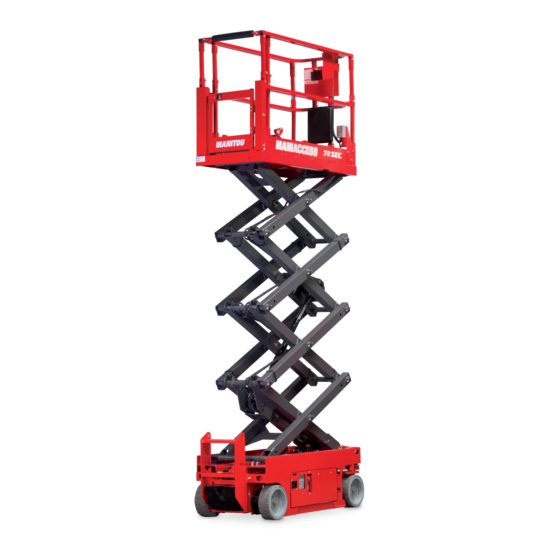
78 SEC 2
100 SEC 2
120 SE 2
OPERATOR'S MANUAL
(ORIGINAL INSTRUCTIONS)
Table of
Contents
Previous
Page
Next
Page
1
2
3
4
5
Advertisement
Table of Contents
Need help?
Do you have a question about the 78 SEC 2 and is the answer not in the manual?
Ask a question
Questions and answers
Related Manuals for Manitou 78 SEC 2
Forklifts Manitou MHT 790 104JD H ST4 S1 Operator's Manual
(175 pages)
Forklifts Manitou MT 732 EASY 75D ST3B S1 Basic Instruction Sheet
(2 pages)
Forklifts Manitou MT 1030 EASY 75D ST3B S2 Operator's Manual
(156 pages)
Forklifts Manitou MT 733 EASY 75D ST5 S1 Basic Instruction Sheet
(2 pages)
Forklifts Manitou MHT-X 780 T-E3 Operator's Manual
(22 pages)
Forklifts Manitou 100 SEC 2 Operator's Manual
(102 pages)
Forklifts Manitou MSI 50 Operator's Manual
(117 pages)
Forklifts Manitou MC 30 Turbo Serie 3-E3 Operator's Manual
(178 pages)
Forklifts Manitou MT6642XT Operators & Service Manual
Telescopic handler (115 pages)
Forklifts Manitou MLT625-75 H S1-E3 Operator's Manual
(160 pages)
Forklifts Manitou MRT 1840 Easy User Handbook Manual
(213 pages)
Forklifts Manitou MLT 845 120 LSU 3-E3 Series Operator's Manual
(128 pages)
Forklifts Manitou ME 418 48V S3 Operator's Manual
(86 pages)
Forklifts Manitou MRT 1440 ST3B Operator's Manual
(246 pages)
Forklifts Manitou MT 1440 A 100D ST5 S1 Operator's Manual
(200 pages)
Forklifts Manitou MT 1440 E3 Operator's Manual
(142 pages)
This manual is also suitable for:
100 sec 2
120 se 2
Table of Contents
Save PDF
Print
Rename the bookmark
Delete bookmark?
Delete from my manuals?
Login
Sign In
OR
Sign in with Facebook
Sign in with Google
Upload manual
Upload from disk
Upload from URL


Need help?
Do you have a question about the 78 SEC 2 and is the answer not in the manual?
Questions and answers