
Subscribe to Our Youtube Channel
Related Manuals for SIGMATEK DIAS-Drive 2000


Summary of Contents for SIGMATEK DIAS-Drive 2000
- Page 1 DIAS-Drive 2000 Power/Axes & Axes Modules Instruction Manual Date of creation: 24.09.2021 Version date: 12.03.2024 Article number: 09-8x-x00-xxx-E...
-
Page 2: Size
(print, photocopy, microfilm or in any other process) without express permission. We reserve the right to make changes in the content without notice. SIGMATEK GmbH & Co KG is not responsible for technical or printing errors in this handbook and assumes no responsibility for damages that occur through... - Page 3 With a power/axis module, several axis modules can be powered. The DIAS-Drive 2000 is a complete servo drive system for the low to mid power range, which can also be used for applications high control performance. It is completely integrated into the LASAL design environment.
-
Page 4: Table Of Contents
DIAS-DRIVE 2000 POWER/AXES & AXES MODULES Table of Contents 1 Introduction 1.1 Target Group/Purpose of this Operating Manual 1.2 Important Reference Documentation 1.3 Contents of Delivery 2 General Instructions 2.1 Abbreviations 2.2 Brief Descriptions Used 2.3 Available Models 2.3.1 Upon Request 3 Basic Safety Directives 3.1 Symbols Used... - Page 5 POWER/AXES & AXES MODULES DIAS-DRIVE 2000 4.2 Safety of the Machine or Equipment 4.3 Directives 4.3.1 Norms 4.3.2 EU Conformity Declaration 4.4 Safety-Relevant Parameters 5 Description of Multi-Converter Systems 5.1 System Components 5.2 Concept 5.3 Function Power/Axis Module 5.4 Function Axis Module 5.5 Software Function...
- Page 6 DIAS-DRIVE 2000 POWER/AXES & AXES MODULES 6.2.2.2 SLA (Safely limited Acceleration) 6.2.2.3 SMA – Safe Maximum Acceleration 6.2.2.4 SLS - Safely Limited Speed 6.2.2.5 SLS with Activation by Delay Time 6.2.2.6 SLS with Activation by Low Speed 6.2.2.7 SLS with Delay Monitoring 6.2.2.8 SMS –...
- Page 7 POWER/AXES & AXES MODULES DIAS-DRIVE 2000 7.7 Expanded MDP 2XXX Specifications 7.7.1 Power Supply 7.7.2 Ballast Resistance 7.8 Communication 7.9 Motor Holding Brake 7.10 Mechanics 7.11 Environmental Conditions 7.12 Miscellaneous 8 Mechanical Dimensions 8.1 Size 1 8.2 Size 2 9 Connectors and Cables 9.1 Size 1 Overview...
- Page 8 DIAS-DRIVE 2000 POWER/AXES & AXES MODULES 9.3.5 X31: Ballast Resistance (MDP 210X, MDP 2200) 9.3.6 X20: +24 V Supply 9.3.7 X21: STO Diagnostic Relays 9.3.8 X22: Safe Inputs/Capture Inputs 9.3.9 X23: Safe Inputs/Capture Inputs/Clock Signal Outputs 9.3.10 VARAN Bus (Industrial Mini I/O) 9.3.11 X11, X12 X13: Optional Encoder Module...
- Page 9 POWER/AXES & AXES MODULES DIAS-DRIVE 2000 10 Configuration and Setting 10.1 Training Opportunities 11 Electrical Configuration 11.1 Motor Selection 11.1.1 Internal 11.1.2 With Encoder Interface 11.1.3 Supplementary Specifications Encoder 11.2 Electrical Installation 11.2.1 Fuse 11.2.2 Guidelines for Installation and Wiring 11.2.3 Protective Earth Connection...
- Page 10 DIAS-DRIVE 2000 POWER/AXES & AXES MODULES 12.4.1 Connecting DC-Link and VARAN 12.5 Installing Universal Encoder Modules 13 Monitoring and Warning Functions 13.1 Error Configuration 13.2 Over Temperature Protection 13.3 Motor Overload Protection 14 Decommissioning and Maintenance 14.1 Repairing Individual Devices 14.2 Maintenance...
-
Page 11: Introduction
POWER/AXES & AXES MODULES DIAS-DRIVE 2000 1 Introduction 1.1 Target Group/Purpose of this Operating Manual This operating manual contains all information required for the operation of the product. This operating manual is intended for: Project planners Technicians Commissioning engineers Machine operators Maintenance/test technicians General knowledge of automation technology is required. -
Page 12: Contents Of Delivery
DIAS-DRIVE 2000 POWER/AXES & AXES MODULES 1.3 Contents of Delivery 1x DIAS-Drive 2000 Component Power/Axis Module MDP: 2x VARAN Mini-I/O-Block (VARAN IN/VARAN OUT) 2x DC-link covers Universal encoder module (optional) Axis Module MDD: 1x Bus Connection Block 1x DC Connection Block... -
Page 13: General Instructions
POWER/AXES & AXES MODULES DIAS-DRIVE 2000 2 General Instructions 2.1 Abbreviations American Wire Gauge Bus Connection Block Cat. Safety category according to ISO 13849-1 Communauté Européenne (Symbol for conformity with EU directives (manufacturer's self- declaration)) CLOCK Clock signal DC Connection Block... -
Page 14: Brief Descriptions Used
DIAS-DRIVE 2000 POWER/AXES & AXES MODULES V AC Alternating current V DC Direct current 2.2 Brief Descriptions Used Power/Axis Module MDP 210X, MDP 2200 Axis Module MDD 210X, MDD 2200 Axis Combination of control and power electronics for a motor within a module. -
Page 15: Basic Safety Directives
POWER/AXES & AXES MODULES DIAS-DRIVE 2000 3 Basic Safety Directives 3.1 Symbols Used The following symbols are used in the operator documentation for warning and danger messages, as well as informational notes. DANGER Danger indicates that death or serious injury will occur, if the specified measures are not taken. - Page 16 DIAS-DRIVE 2000 POWER/AXES & AXES MODULES CAUTION Caution indicates that moderate to slight injury can occur, if the specified measures are not taken. To avoid moderate to slight injuries, observe all guidelines. Attention indique une situation dangereuse qui, faute de prendre les mesures adéquates, peut entraîner des blessures assez graves ou...
-
Page 17: Disclaimer
Please thoroughly read the corresponding documents and this operating manual before handling a product. SIGMATEK GmbH & Co KG is not liable for damages caused through, non-compliance with these instructions or applicable regulations. -
Page 18: General Safety Directives
Regarding the requirements for Safety and health connected to the use of machines, the manufacturer must perform a risk assessment in accordance with machine directives 2006/42/EG before introducing a machine to the market. Operate the unit with devices and accessories approved by SIGMATEK only. Page 18 12.03.2024... - Page 19 POWER/AXES & AXES MODULES DIAS-DRIVE 2000 CAUTION Handle the device with care and do not drop or let fall. Prevent foreign bodies and fluids from entering the device. The device must not be opened! Manipulez l’appareil avec précaution et ne le laissez pas tomber.
-
Page 20: Designated Use
POWER/AXES & AXES MODULES 3.4 Designated Use The PDS of the DIAS-Drive 2000 series are designed exclusively for use in the control cabinet with the supply /axis modules, of the same series. They are combined and installed as components in electrical equipment and machines and can only be operated such machines and equipment. - Page 21 POWER/AXES & AXES MODULES DIAS-DRIVE 2000 CAUTION The instructions contained in this operating manual must be followed. Installation, mounting, programming, initial start-up, operation, maintenance and decommissioning can only be performed by qualified personnel. Qualified personnel in this context are people, who have completed...
-
Page 22: Danger Electrical Shock
DIAS-DRIVE 2000 POWER/AXES & AXES MODULES 3.5 Danger Electrical Shock DANGER During installation and operation, an especially high risk of electric shock exists. Conductive components cannot be handled. Il existe un risque de choc électrique pendant l'installation et l'utilisation. Les pièces sous tension ne doivent pas être touchées. -
Page 23: Hot Surface Warning
POWER/AXES & AXES MODULES DIAS-DRIVE 2000 1. Disconnect electrical circuits from voltage supply (including electronics and auxiliary circuits) 2. secure against restarting. 3. Verify voltage-free condition 4. Ground and short circuit 5. cover or cordon off any neighboring voltage-carrying components After competing the work, the safety measures taken must be removed in reverse order. -
Page 24: Operation Modes
Drive 2000. Which safety functions are to be used for the application is defined via a configuration file. The complete safety functions of the DIAS-Drive 2000 can be used in a system with a SIGMATEK FSoE safety controller (e.g. SCP 111). In addition to the safety PLC, the complete system consists of a functional PLC ( e.g. -
Page 25: Safe State
DIAS-DRIVE 2000 3.8 Safe State The safe state of the DIAS-Drive 2000 is defined by STO. The motor supply is switched off on two channels. Thus, no motor torque is generated. This state can be triggered by the application or by configurable inputs. The safety functions can also trigger STO if their limits are violated, among other things. -
Page 26: Software/Training
DIAS-DRIVE 2000 POWER/AXES & AXES MODULES INFORMATION Default delivery: SS1 for all axes (500 ms ramp time) With cross-circuit detection - output 1 (clock A) must be connected to input 1 and output 2 (clock B) to input 2. See 6.3 Wiring Examples Safety. -
Page 27: Standards And Directives
POWER/AXES & AXES MODULES DIAS-DRIVE 2000 4 Standards and Directives 4.1 Residual Risks CAUTION The following residual risks for the product must be included in the system integrator's risk assessment: Release of non-environmentally safe substances, emissions and unusual temperatures Hazardous contact voltages... -
Page 28: Safety Of The Machine Or Equipment
DIAS-DRIVE 2000 POWER/AXES & AXES MODULES 4.2 Safety of the Machine or Equipment INFORMATION Observe all on-site rules and regulations for accident prevention and occupational safety. 4.3 Directives The product was constructed in compliance with the following European Union directives and tested for conformity. -
Page 29: Eu Conformity Declaration
POWER/AXES & AXES MODULES DIAS-DRIVE 2000 4.3.2 EU Conformity Declaration EU Declaration of Conformity The product DIAS-Drive 2000 conforms to the following European directives: 2006/42/EG Machine Directive 2014/30/EU Electromagnetic Compatibility (EMC Directive) 2011/65/EU “Restricted use of certain hazardous substances in electrical and electronic equipment”... - Page 30 DIAS-DRIVE 2000 POWER/AXES & AXES MODULES 4.7E-09 (1/h) MTTF 453 years 99 % Parameter Safety Function SOS, SLS, SS1, SS2, SMS, SLP, SLA, SLI, SDI, SMP, SMA, SSM, SCA gemäß EN 62061 SIL 3, HFT 1 PL-Kategorie gemäß EN ISO PL e / Cat. 4...
-
Page 31: Description Of Multi-Converter Systems
POWER/AXES & AXES MODULES DIAS-DRIVE 2000 5 Description of Multi-Converter Systems The DIAS-Drive 2000 series is a multi-converter system for synchronous motors. The device configuration can consist of several power/axis modules (MDP 2XXX) and up to 10 axis modules (MDD 2XXX). -
Page 32: Concept
POWER/AXES & AXES MODULES 5.2 Concept The servo drive systems of the DIAS-Drive 2000 series consist of: Power/axis module with integrated IGBT power outputs for up to three axes Axis modules with IGBT power outputs for up to three axes power input of the power/axis module with integrated power filter for EN 61800 C3, rectifier and inrush current limiting. -
Page 33: Function Power/Axis Module
POWER/AXES & AXES MODULES DIAS-DRIVE 2000 Protective functions against: DC-link circuit Under/overvoltage Several short circuit conditions Phase error in the main voltage supply Ballast resistor over heating Over temperature (heat sink, ambient and motor) INFORMATION For USA: The integrated contactless short-circuit detector does not serve as branch... -
Page 34: Software Function
DIAS-DRIVE 2000 POWER/AXES & AXES MODULES 5.5 Software Function Field-oriented current controller (Cycle time 62.5 µs) Feedback detection and speed controller (access time 62.5 µs) Spline interpolation and position controller (cyclic time 62.5 µs) full synchronization up to the output stage to the control frequency with cycle times of 250 µs, 500 µs and 1 ms to 8 ms... -
Page 35: Safety Functions
6 Safety Functions 6.1 Overview The devices of the series DIAS-Drive 2000 have the following safety features: Safe Torque Off (does not require safe position detection) Safe Stop 1 (does not require safe position detection if SS1 with time control) - Page 36 DIAS-DRIVE 2000 POWER/AXES & AXES MODULES Safety functions such as Safe Limited Speed require safe position detection. In order to be able to implement the requirement according to EN ISO 13849, category 4, it must be possible to represent a continuous 2-channel structure.
-
Page 37: Description Of The Safety Functions
POWER/AXES & AXES MODULES DIAS-DRIVE 2000 6.2 Description of the Safety Functions 6.2.1 Stop Functions The different stop functions are explained below. 6.2.1.1 STO - Safe Torque Off 6.2.1.2 SS1 – Safe Stop 1 6.2.1.3 SS1 with Constant Time Delay 6.2.1.4 SS1 with Speed Monitoring... -
Page 38: Sto - Safe Torque Off
DIAS-DRIVE 2000 POWER/AXES & AXES MODULES 6.2.1.1 STO - Safe Torque Off With the STO safety function the drive can be safely switched momentlessly and the axis can thus be brought to a standstill without being controlled. As soon as the function is executed, no more torque can be built up. - Page 39 POWER/AXES & AXES MODULES DIAS-DRIVE 2000 Functional Description By activating the STO control bit, the drive is switched momentlessly and the axis is brought to an uncontrolled standstill (1). From this point on, the axis can no longer be controlled and will coast to a stop, if it was previously in motion.
-
Page 40: Ss1 With Constant Time Delay
DIAS-DRIVE 2000 POWER/AXES & AXES MODULES 6.2.1.2 SS1 – Safe Stop 1 With the SS1 safety function the drive can be switched momentless with a time delay and the axis can thus be brought to a controlled standstill. The function related part can brake the axis appropriately during the execution of SS1 to prevent it from spinning out. - Page 41 POWER/AXES & AXES MODULES DIAS-DRIVE 2000 The sequence shown in the figure shows the standard variant of SS1, where the SS1 trigger (control bit) is active for longer than t . In the sequence shown in the following figure, in comparison, the trigger is activated only for a short moment.
- Page 42 DIAS-DRIVE 2000 POWER/AXES & AXES MODULES Functional Description By activating SS1 (t ) the timer starts counting, which leads to the execution of the safety function STO, after t has expired. The activation of SS1 is communicated to the function related part and signaled via the status bit, so that the brakes can be applied accordingly.
-
Page 43: Ss1 With Speed Monitoring
POWER/AXES & AXES MODULES DIAS-DRIVE 2000 6.2.1.4 SS1 with Speed Monitoring In addition to the standard variant, the speed can be monitored to trigger STO prematurely, if the speed is in the zero window (n ) long enough (t zero... -
Page 44: Ss1 With Deceleration Monitoring
DIAS-DRIVE 2000 POWER/AXES & AXES MODULES 6.2.1.5 SS1 with Deceleration Monitoring In addition to the monitoring already mentioned, the deceleration can also be monitored with SS1. This monitors, whether the speed is within the configured ramp during the braking process. This means, that it can be detected at an early stage, whether braking is working and STO can be triggered earlier in the event of an error. -
Page 45: Ss1 With Sbc
POWER/AXES & AXES MODULES DIAS-DRIVE 2000 Functional Description The temporal behavior of SS1 remains unchanged. In addition, the delay of the speed is monitored. Since the function related part cannot start braking immediately, a delay (t ) is waited for... - Page 46 DIAS-DRIVE 2000 POWER/AXES & AXES MODULES Timing The figure shows the same example as in the last figure but with additional SBC option. Therefore, the respective SS1 checks do not directly lead to SS1 finalization followed by STO, but as previously described first to the triggering of SBC. Only the case marked with arrow (1) does not delay the STO execution backwards, but executes SBC correspondingly earlier.
- Page 47 POWER/AXES & AXES MODULES DIAS-DRIVE 2000 Error Reaction With SS1 2 different types of errors can occur: Speed at the end not within the zero window: If the zero window is configured, the speed must be within the zero window (between -n...
- Page 48 DIAS-DRIVE 2000 POWER/AXES & AXES MODULES The error case shown in the figure shows the behavior of SS1, when the speed is outside the zero window, after t has elapsed. The following diagram shows the error case for delay monitoring.
- Page 49 POWER/AXES & AXES MODULES DIAS-DRIVE 2000 6.2.1.7 SS2 – Safe Stop 2 With the SS2 safety function the drive can be stopped in a controlled manner without the axis being switched momentless. As a result, the SOS safety function is executed to hold the axis at the current position.
-
Page 50: Ss2 With Constant Time Delay
DIAS-DRIVE 2000 POWER/AXES & AXES MODULES 6.2.1.8 SS2 with Constant Time Delay The standard and at the same time minimum variant of SS2 is the one with time-delayed SOS. In this case, SOS is triggered after execution of SS2 after a set waiting time (t... - Page 51 POWER/AXES & AXES MODULES DIAS-DRIVE 2000 By activating SS2 (t ), the timer starts counting, which leads to the execution of the associated safety function SOS, after t has elapsed. By "associated" is meant, that for the 4th instance of SS2 (SS2_4) also the 4th instance of SOS (SOS_4) is used as a subsequent function.
-
Page 52: Ss2 With Speed Monitoring
DIAS-DRIVE 2000 POWER/AXES & AXES MODULES However, if SS2 triggering is removed prematurely (see t in "SS2 with Constant Time Delay" figure 2), the function is still finalized and SOS is executed at the end for only one cycle (if automatic restart is configured). -
Page 53: Ss2 With Deceleration Monitoring
POWER/AXES & AXES MODULES DIAS-DRIVE 2000 Functional Description In order to be able to trigger SOS before the time t has elapsed in the event of a faster deceleration, speed monitoring can also be activated. This speed monitoring checks, if the... - Page 54 DIAS-DRIVE 2000 POWER/AXES & AXES MODULES Functional Description The temporal behavior of SS2 remains unchanged. In addition, the delay of the speed is monitored. Since the function related part cannot start braking immediately, a delay (t ) is waited for...
- Page 55 POWER/AXES & AXES MODULES DIAS-DRIVE 2000 The described error case is shown below with the help of a timing diagram. The time of the error is marked with t Parameters Time SOS (t Timespan until SOS is activated. This activates the same instance of SOS (e.g.
-
Page 56: Monitoring Functions
DIAS-DRIVE 2000 POWER/AXES & AXES MODULES 6.2.2 Monitoring Functions The different monitoring functions are explained below. 6.2.2.1 SOS – Safe Operation Stop 6.2.2.2 SLA (Safely limited Acceleration) 6.2.2.3 SMA – Safe Maximum Acceleration 6.2.2.4 SLS - Safely Limited Speed 6.2.2.5 SLS with Activation by Delay Time 6.2.2.6 SLS with Activation by Low Speed... -
Page 57: Sos - Safe Operation Stop
POWER/AXES & AXES MODULES DIAS-DRIVE 2000 6.2.2.1 SOS – Safe Operation Stop This function prevents the motor from deviating from the stop position by more than a specified amount. The drive is supplied with energy that enables it to withstand being attacked by external forces. - Page 58 DIAS-DRIVE 2000 POWER/AXES & AXES MODULES Functional Description With the activation of SOS by the control bit (t ) the monitoring of the position is started. First the position measured at time t is stored as the initial position. Then it is checked, whether the...
- Page 59 POWER/AXES & AXES MODULES DIAS-DRIVE 2000 The two error cases are shown below with the help of timing diagrams. The time of the error is marked with t In the error case shown, it can be seen, that after the error has been detected (t...
- Page 60 DIAS-DRIVE 2000 POWER/AXES & AXES MODULES The error case with activated speed monitoring is shown below: Parameters Position Tolerance (s Tolerance for position 0 zero Velocity Zero-Window (n Optional: Tolerance for velocity 0 zero Error Reaction Function started in case of an error Possible entries: STO, SS1_1,…SS1_8...
-
Page 61: Sla (Safely Limited Acceleration)
POWER/AXES & AXES MODULES DIAS-DRIVE 2000 6.2.2.2 SLA (Safely limited Acceleration) If the same acceleration or deceleration limits are to be used for both directions of rotation, the following applies: = -a acc_limit_pos acc_limit_neg = -a dec_limit_pos dec_limit_neg The SLA safety function can be used to restrict the acceleration of the drive to a configurable range. - Page 62 DIAS-DRIVE 2000 POWER/AXES & AXES MODULES Functional Description With the activation of SLA by the control bit (t ) a timer is started, which starts the monitoring of the acceleration/deceleration, after the time t has elapsed. Until it has expired (t ), the configured limit values may still be exceeded.
- Page 63 POWER/AXES & AXES MODULES DIAS-DRIVE 2000 The described error case is shown below with the help of a timing diagram. The time of the error is marked with t The error case shown indicates, that when the acceleration limit is exceeded (depending on the direction of rotation), the configured error reaction is triggered immediately.
- Page 64 DIAS-DRIVE 2000 POWER/AXES & AXES MODULES Parameters Error Reaction Function started in case of an error Possible entries: STO, SS1_1,…SS1_8 Page 64 12.03.2024...
-
Page 65: Sma - Safe Maximum Acceleration
POWER/AXES & AXES MODULES DIAS-DRIVE 2000 6.2.2.3 SMA – Safe Maximum Acceleration The SMA safety function can be used to limit the maximum acceleration or deceleration of the drive. The function is active by parameterization and executes the configured error reaction, when the set limit values are exceeded. - Page 66 DIAS-DRIVE 2000 POWER/AXES & AXES MODULES Error Reaction Only one error can occur with SMA: Permitted acceleration/deceleration exceeded: If SMA is parameterized, the acceleration/deceleration must be within the set limit values depending on the direction of rotation. Should an overrun be detected, the configured error reaction is triggered.
-
Page 67: Sls - Safely Limited Speed
POWER/AXES & AXES MODULES DIAS-DRIVE 2000 6.2.2.4 SLS - Safely Limited Speed The SLS safety function can be used to limit the speed of the drive. While the function is active, the speed is monitored for compliance with the configured limit values. -
Page 68: Sls With Activation By Low Speed
DIAS-DRIVE 2000 POWER/AXES & AXES MODULES Functional Description With the activation of SLS by the control bit (t ) a timer is started, which starts the monitoring of the speed after the time t has elapsed. Until this has expired (t ), the speed may still exceed the configured limits. -
Page 69: Sls With Delay Monitoring
POWER/AXES & AXES MODULES DIAS-DRIVE 2000 Functional Description Similar to SS1 and SS2, in addition to the time delay, the speed can be checked to start speed monitoring ahead of time. For this the time t must be configured with a value unequal 0. - Page 70 DIAS-DRIVE 2000 POWER/AXES & AXES MODULES Functional Description The temporal behavior of SLS remains unchanged. In addition, the delay of the speed is monitored. Since the function related part cannot start braking immediately, a delay (t ) is waited for...
- Page 71 POWER/AXES & AXES MODULES DIAS-DRIVE 2000 The two error cases are shown below with the help of timing diagrams. The time of the error is marked with t The figure shows the behavior of SLS, when the speed leaves the permitted range, while speed monitoring is already active (the behavior of STO is shown as the error reaction).
- Page 72 DIAS-DRIVE 2000 POWER/AXES & AXES MODULES Parameters Time Velocity (t Maximum time to reach the limit values Upper Limit (n Maximum value for velocity upper_limit Lower Limit (n Minimum value for velocity lower_limit Time Velocity Limit (t Optional: Time until velocity monitoring is activated after limit values are...
-
Page 73: Sms - Safe Maximum Speed
POWER/AXES & AXES MODULES DIAS-DRIVE 2000 6.2.2.8 SMS – Safe Maximum Speed With the SMS safety function, the maximum speed of the drive can be restricted. The function is active by parameterization and executes the configured error reaction, when the set limit values are exceeded. - Page 74 DIAS-DRIVE 2000 POWER/AXES & AXES MODULES The described error case is shown below with the help of a timing diagram. The time of the error is marked with t The example above shows an error case with STO as error reaction. Speed monitoring...
-
Page 75: Slp - Safely Limited Position
POWER/AXES & AXES MODULES DIAS-DRIVE 2000 6.2.2.9 SLP - Safely Limited Position With the SLP safety function the position of the drive can be restricted to a configurable range. While the function is active, the position is monitored for compliance with the configured limit values. - Page 76 DIAS-DRIVE 2000 POWER/AXES & AXES MODULES Functional Description With the activation of SLP by the control bit (t ) the monitoring of the position is started immediately. It remains active, until SLP (t ) is deactivated. If the function is configured with the setting "Region = inside window", the position may only...
- Page 77 POWER/AXES & AXES MODULES DIAS-DRIVE 2000 The described error case is shown below with the help of two timing diagrams. The time of the error is marked with t In both error cases shown, position monitoring is continued, so that in the event of an error acknowledgment and SLP remaining active, an error is immediately detected again.
- Page 78 DIAS-DRIVE 2000 POWER/AXES & AXES MODULES Parameters Upper Limit (s Upper limit for position upper_limit Lower Limit (s Lower limit for position lower_limit Error Reaction Function started in case of an error Possible entries: STO, SS1_1,…SS1_8 Region Position must be inside or outside the limits...
-
Page 79: Sli - Safely Limited Increment
POWER/AXES & AXES MODULES DIAS-DRIVE 2000 6.2.2.10 SLI - Safely Limited Increment The SLI safety function can be used to restrict the movement of the drive. As soon as the function is active, the position may only change upwards or downwards by the set values. The position determined, at the time the function was activated, is used as the basis. - Page 80 DIAS-DRIVE 2000 POWER/AXES & AXES MODULES Error Reaction Only one error can occur with SLI: Permitted position change exceeded: When monitoring is active, the position, starting from the initial position determined when the safety function was activated, may only change by the set values. Should an overrun be detected, the configured error reaction is triggered.
-
Page 81: Sdi - Safe Direction
POWER/AXES & AXES MODULES DIAS-DRIVE 2000 6.2.2.11 SDI – Safe Direction With the SDI safety function, the direction of rotation of the drive can be restricted. Once the function is active, only the positive or negative direction of rotation is allowed, depending on the configuration. - Page 82 DIAS-DRIVE 2000 POWER/AXES & AXES MODULES Functional Description With SDI configuration parameters can be used to set, whether only the positive or only the negative direction of rotation should be allowed, while SDI is active. The restriction to "only positive direction of rotation allowed" is exemplified in the first figure, while the variant "only negative direction of rotation allowed"...
- Page 83 POWER/AXES & AXES MODULES DIAS-DRIVE 2000 Error Reaction With SDI 2 different types of errors can occur: Speed in non-permitted direction of rotation too high: While monitoring is active, the speed must not fall below the value -n , if the direction of rotation is only...
- Page 84 DIAS-DRIVE 2000 POWER/AXES & AXES MODULES The following shows the error case with low speed but position violation: Parameters Direction This direction is allowed for movement, opposite direction is monitored (limited), possible entries: positive, negative Position Zero-Window (s Tolerance for position...
-
Page 85: Sca - Safe Cam
POWER/AXES & AXES MODULES DIAS-DRIVE 2000 6.2.2.12 SCA - Safe CAM The position of the drive can be monitored with the SCA safety function. The function is active by parameterization and signals with the status bit, whether the set limits are currently being observed or have been exceeded. -
Page 86: Ssm - Safe Speed Monitor
DIAS-DRIVE 2000 POWER/AXES & AXES MODULES 6.2.2.13 SSM - Safe Speed Monitor This function provides a safe output signal to indicate whether the motor speed is within a defined limit value. With the SSM safety function the speed of the drive can be monitored. The function is active by parameterization and signals with the status bit, whether the set limits are currently being observed or have been exceeded. -
Page 87: Output Functions Per Axis
POWER/AXES & AXES MODULES DIAS-DRIVE 2000 6.2.3 Output Functions per Axis The different output functions are explained below. 6.2.3.1 SBC - Safe Brake Control 6.2.3.2 SBT – Safe Brake Test 12.03.2024 Page 87... -
Page 88: Sbc - Safe Brake Control
DIAS-DRIVE 2000 POWER/AXES & AXES MODULES 6.2.3.1 SBC - Safe Brake Control With the SBC safety function the holding brake (if present) of the drive can be safely closed. The function can be used independently, but also together with STO and SS1. The independent use is described below. -
Page 89: Sbt - Safe Brake Test
POWER/AXES & AXES MODULES DIAS-DRIVE 2000 6.2.3.2 SBT – Safe Brake Test The SBT function is not a safety function in the conventional sense, but a diagnostic function for the service brake. With SBT, the brake is tested with a defined torque. In this process, current is injected into the drive for the duration "Test Duration Time". - Page 90 DIAS-DRIVE 2000 POWER/AXES & AXES MODULES Timing In order to better describe the temporal relationships during test execution, an exemplary sequence is shown in the following figure: The presented process consists of 5 phases, of which the first and last phase concern only the function related part.
- Page 91 POWER/AXES & AXES MODULES DIAS-DRIVE 2000 Phase 1 – Load Determination When preparation is complete, the function related part triggers the brake test in the safety related part. From this point in time (t ), the brake test thus runs both function related and safety related.
- Page 92 DIAS-DRIVE 2000 POWER/AXES & AXES MODULES Phase 3 – Check Brake In this phase, the previously applied test current I is held for the duration t test load test_duration while the brake remains closed. The position must not change in the process, which is why a...
- Page 93 POWER/AXES & AXES MODULES DIAS-DRIVE 2000 SBT Error During the preparation time the After parameter “Error Reaction” position changes by more than "Position Limit Preparation" During the test phase the position After parameter “Error Reaction” changes by more than "Position Limit Test"...
-
Page 94: Wiring Examples Safety
DIAS-DRIVE 2000 POWER/AXES & AXES MODULES 6.3 Wiring Examples Safety To be able to execute the configured safety functions, they must be controlled via safe digital inputs. Dual channel mapping is used here. 6.3.1 Dual Channel Input Mapping 4 inputs are available. For dual channel mapping, 2 inputs must always be considered in... - Page 95 POWER/AXES & AXES MODULES DIAS-DRIVE 2000 An MDD 2000 with cross-connection testing: here, the clock output signals A & B are connected with the safe inputs SI1&2. 12.03.2024 Page 95...
- Page 96 DIAS-DRIVE 2000 POWER/AXES & AXES MODULES Multiple MDD 2000 with cross-circuit testing: Page 96 12.03.2024...
-
Page 97: Preconditions For Safety Functions
The use of safe Hiperface DSL encoders requires verification of the encoders. The verification process is executed from the functional application and is done using a predefined flow. The DIAS-Drive 2000 runs in a restricted functional mode until the verification is completed. 12.03.2024... -
Page 98: Technical Data
DIAS-DRIVE 2000 POWER/AXES & AXES MODULES 7 Technical Data 7.1 DC-link Circuit Module MDP/MDD 2102 MDP/MDD 2100 MDP/MDD 2200 Effective nominal power 1.3 kW 2.6 kW for 4 kW 8 kW for 9 kW 18 kW for 10 s 10 s 10 s Intermediate circuit nominal 325 V 565 V 565 V... -
Page 99: Axis/Motor Connection
POWER/AXES & AXES MODULES DIAS-DRIVE 2000 7.3 Axis/Motor Connection Module MDP/MDD 210X MDP/MDD 2200 Maximum number of drives Switching frequency 8 kHz Derating 2.5 %/°C over 45 °C (axis current and DC-link power are affected) Continuous current/peak current for 1 s per axis... -
Page 100: Signal Output For Cross-Circuit Detection
DIAS-DRIVE 2000 POWER/AXES & AXES MODULES 7.5 Signal Output for Cross-Circuit Detection Module MDP/MDD 210X MDP/MDD 2200 Number 1x signal A per module 1x signal B per module Rated output voltage +24 V Output voltage range +22-30 V Output current... -
Page 101: Encoder Interface
POWER/AXES & AXES MODULES DIAS-DRIVE 2000 7.6 Encoder Interface Module MDP/MDD 210X MDP/MDD 2200 Internal Maximum amount Type Hiperface DSL Connection type Single cable solution Power supply 12 V Optional Maximum amount Type Resolver/Sin-Cos/TTL/Hiperface/EnDAT 2.1/Tamagawa/BiSS-C Voltages 5 V (with Remote Sensing)/9 V... -
Page 102: Expanded Mdp 2Xxx Specifications
DIAS-DRIVE 2000 POWER/AXES & AXES MODULES 7.7 Expanded MDP 2XXX Specifications 7.7.1 Power Supply Module MDP 2102 MDP 2100 MDP 2200 Rated supply voltage 1x 230 V AC 3x 400 V AC Supply voltage range 1x 230 V AC ±10 % 3x 380-480 V AC ±10 %... -
Page 103: Ballast Resistance
POWER/AXES & AXES MODULES DIAS-DRIVE 2000 7.7.2 Ballast Resistance Module MDP 2102 MDP 2100 MDP 2200 Internal brake resistor available yes (25 Ω) yes (25 Ω) yes (25 Ω) Peak power int./ext. 7.4 kW/12.3 kW 28.9 kW/28.9 kW 28.9 kW/36.1 kW Continuous power int./ext. -
Page 104: Mechanics
DIAS-DRIVE 2000 POWER/AXES & AXES MODULES Overload and short-circuit protection Under voltage monitor Cable break monitor Brake voltage reduction yes (12-24 V) 7.10 Mechanics Module MDP/MDD 210X MDP/MDD 2200 Cooling Air, Cold-Plate in preparation Backplane not required Mounting position vertically hanging... -
Page 105: Environmental Conditions
POWER/AXES & AXES MODULES DIAS-DRIVE 2000 7.11 Environmental Conditions Module MDP/MDD 210X MDP/MDD 2200 Storage temperature -25 ... +70 °C Nominal environmental temperature 0 ... +45 °C Environmental temperature max. 0 ... +55 °C (with derating 2.5 %/°C above 45 °C) -
Page 106: Mechanical Dimensions
DIAS-DRIVE 2000 POWER/AXES & AXES MODULES 8 Mechanical Dimensions 8.1 Size 1 Page 106 12.03.2024... - Page 107 POWER/AXES & AXES MODULES DIAS-DRIVE 2000 8.2 Size 2 12.03.2024 Page 107...
-
Page 108: Connectors And Cables
DIAS-DRIVE 2000 POWER/AXES & AXES MODULES 9 Connectors and Cables 9.1 Size 1 Overview 9.1.1 Size 1 Front Interfaces Page 108 12.03.2024... -
Page 109: Size 1 Top Interfaces
POWER/AXES & AXES MODULES DIAS-DRIVE 2000 9.1.2 Size 1 Top Interfaces 12.03.2024 Page 109... -
Page 110: Size 1 Bottom Interfaces (Power/Axis Module)
DIAS-DRIVE 2000 POWER/AXES & AXES MODULES 9.1.3 Size 1 Bottom interfaces (Power/Axis Module) Page 110 12.03.2024... -
Page 111: Size 2 Overview
POWER/AXES & AXES MODULES DIAS-DRIVE 2000 9.2 Size 2 Overview 9.2.1 Size 2 Front Interfaces 12.03.2024 Page 111... -
Page 112: Size 2 Top Interfaces
DIAS-DRIVE 2000 POWER/AXES & AXES MODULES 9.2.2 Size 2 Top Interfaces Page 112 12.03.2024... -
Page 113: Size 2 Bottom Interfaces (Power/Axis Module)
POWER/AXES & AXES MODULES DIAS-DRIVE 2000 9.2.3 Size 2 Bottom interfaces (Power/Axis Module) 9.3 Connector Layout 9.3.1 X1, X2, X3: Motor Connection not included in delivery Weidmüller (1080440000) BVF 7.62HP/04/180 BCF/06R SN BK BX Article number: 4080221212 Function Hiperface DSL+... -
Page 114: Pin Assignment Hiperface Dsl Cable
DIAS-DRIVE 2000 POWER/AXES & AXES MODULES 9.3.1.1 Pin Assignment Hiperface DSL Cable Connector Layout Variant 1 (Hiperface DSL) BVF 7.62HP/04/180... Function Color Epic LS1 D6 3+PE+4 K 10.5-15.5 Hiperface DSL+ Not defined Hiperface DSL- Not defined Motor brake+ Not defined... -
Page 115: X30 Bg1: Power Supply (Mdp 2100)
POWER/AXES & AXES MODULES DIAS-DRIVE 2000 9.3.3 X30 BG1: Power Supply (MDP 2100) Function Ground wire Power phase L1 Power phase L2 Power phase L3 9.3.4 X30 BG2: Power Supply (MDP 2200) Function Ground wire Power phase L1 Power phase L2 Power phase L3 9.3.5 X31: Ballast Resistance (MDP 210X, MDP 2200) -
Page 116: X20: +24 V Supply
DIAS-DRIVE 2000 POWER/AXES & AXES MODULES 9.3.6 X20: +24 V Supply Function +24 V 9.3.7 X21: STO Diagnostic Relays Function STO DIAG RELAIS NC1 STO DIAG RELAIS NC2 STO DIAG RELAIS NO1 STO DIAG RELAIS NO2 9.3.8 X22: Safe Inputs/Capture Inputs Configuration see following chapter "Wiring Examples Safety"... -
Page 117: X11, X12 X13: Optional Encoder Module
POWER/AXES & AXES MODULES DIAS-DRIVE 2000 Function Tx+/Rx+ Tx-/Rx- Rx+/Tx+ n.c. n.c. Rx-/Tx- n.c. n.c. 9.3.11 X11, X12 X13: Optional Encoder Module Function +9 V +5 V Encoder B+ Encoder B- Encoder A+ Encoder A- Clock-/B- Clock+/B+ Data-/A- Data+/A+ n.c. -
Page 118: Endat Cable Pin Assignment
DIAS-DRIVE 2000 POWER/AXES & AXES MODULES Function 5 V Sense+ Battery Battery+ Manufacturer Article Number Description Specification Hirose 4080225722 DH-27-CT1B plug cover case metal button type Hirose 4080225723 DH40-27S plug unit - solder contact solder contacts type Hirose 4080225725 DH-27-CMB(6.9) 244-... -
Page 119: Resolver Cable Pin Assignment
POWER/AXES & AXES MODULES DIAS-DRIVE 2000 9.3.11.2 Resolver Cable Pin Assignment Connector Layout Variant 2 (Resolver) Drive Function Color Twisted Pair Motor Resolver Cosinus- Pair 1 Resolver Cosinus+ orange Pair 1 Resolver Sinus- green Pair 2 Resolver Sinus+ yellow Pair 2... -
Page 120: Biss-C Cable Pin Assignment
DIAS-DRIVE 2000 POWER/AXES & AXES MODULES 9.3.11.4 BiSS-C Cable Pin Assignment Connector Layout Variant 1 (BiSS-C) Drive Function Color Twisted Pair Motor white Pair 1 grey Pair 1 Clock-/B- orange/white Pair 2 Clock+/B+ red/white Pair 2 Data-/A- violet Pair 3... -
Page 121: Status Leds
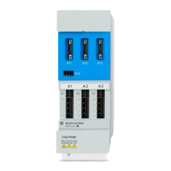
POWER/AXES & AXES MODULES DIAS-DRIVE 2000 9.4 Status LEDs 3 status LEDs are located on the front panel of the DIAS-Drive 2000 series, which are used to read the drive states. The LEDs are labeled A1-A3 (Axis 1, Axis 2, Axis 3) 12.03.2024... -
Page 122: Cable Cross Sections
DIAS-DRIVE 2000 POWER/AXES & AXES MODULES Color Status Frequency Definition blinks 2x blink - Pause - 2x blink ... Error in the Start-up phase Yellow blinks Slow blink Start-up phase Blue blinks Slow blink Firmware update blinks Fast blinking frequency:... -
Page 123: X30 Bg1 (Power Supply), X31 (Ballast Resistor), X20 (+24 V Supply)
POWER/AXES & AXES MODULES DIAS-DRIVE 2000 Fine-stranded wire, H05(07) V-K (signal) 0.14-1.5 mm with AEH with collar DIN 46 228/4, (power) 0.5-6 mm with AEH with collar DIN 46 228/4, (signal) 0.25-1.5 mm with ferrule according to DIN 46 228/1, (power) 0.5-6 mm... -
Page 124: X30 Bg2 (Power Supply)
DIAS-DRIVE 2000 POWER/AXES & AXES MODULES 9.5.3 X30 BG2 (power supply) Connector type: Weidmüller (1060410000) BVFL 7.62HP/04/180 SN BK BX Terminal range, min. 0.5 mm Terminal range, max. 10 mm Single-wire, min. H05(07) V-U 0.5 mm Single-wire, max. H05(07) V-U 10 mm Multi-strand max. -
Page 125: Cable Lengths
POWER/AXES & AXES MODULES DIAS-DRIVE 2000 Conductor cross section flexible with ferrule with plastic sleeve: 0.25-0.75 mm (reason for reduction d2 of the ferrule) 9.6 Cable Lengths The cross sections of the cable depends on the configuration used and must be selected so that the nominal requirements are met. -
Page 126: Cable Strain Relief
DIAS-DRIVE 2000 POWER/AXES & AXES MODULES 9.7 Cable Strain Relief In order to avoid unnecessary strain on the connected plugs, and also as a safeguard, a strain relief can be used to affix the cable to the housing. As an alternative, the cable can be places in a cable channel over the shortest distance possible. -
Page 127: Power Supply
The maximum cable length from the first device to the primary bus participants is 100 m. The contacts must be made in compliance with TIA- 568A/B. The appropriate cable configurations can be found on the SIGMATEK homepage. 9.8.3 DC-link Circuit For the DC-link connection, the DC connection blocks (included with delivery) from SIGMATEK GmbH &... -
Page 128: Encoder Cables
POWER/AXES & AXES MODULES 9.8.5 Encoder Cables Endat/Hiperface Lapp 00277101 Resolver Lapp 00277151 Equivalent cables s are also authorized. INFORMATION The appropriate motor and encoder cables can be ordered from SIGMATEK, see chapter 17.1 Cable Type Key Page 128 12.03.2024... -
Page 129: Configuration And Setting
DIAS-DRIVE 2000 10 Configuration and Setting The modules of the DIAS-Drive 2000 series are integrated into the design environment LASAL. There, the devices can be configured and linked with control programs. In addition, LASAL has numerous debugging functions the simplify trouble shooting on the machine are available. -
Page 130: Electrical Configuration
POWER/AXES & AXES MODULES 11 Electrical Configuration 11.1 Motor Selection With the DIAS-Drive 2000 series, synchronous servo motors can be controlled. The motors must meet the requirements specified in the technical data. INFORMATION During the initial start-up, ensure that the motor parameters are set correctly. -
Page 131: Supplementary Specifications Encoder
POWER/AXES & AXES MODULES DIAS-DRIVE 2000 11.1.3 Supplementary Specifications Encoder Type Specification Resolver Excitation frequency of 8 kHz or higher Endat 2.1 Maximum frequency of incremental signals 1 MHz Hiperface Identifier Encoder designation example 0x02 SCS60 0x07 SCM60 0x12 SNS50... -
Page 132: Electrical Installation
11.2 Electrical Installation The following sections describe the electrical installation and wiring of the converter system and are generally based on the modules of the DIAS-Drive 2000 series. 11.2.1 Fuse The supply line of the devices must be protected with a fuse. The dimensioning of the fuse depends on the application, however, the “Maximum Fuse Protection”... -
Page 133: Protective Earth Connection
POWER/AXES & AXES MODULES DIAS-DRIVE 2000 11.2.3 Protective Earth Connection 12.03.2024 Page 133... -
Page 134: Protective Earth Connection Between Multiple Modules
DIAS-DRIVE 2000 POWER/AXES & AXES MODULES The connection of the protective earth must be made as follows: The protective earth must have a minimum cross section according to the table. Each protective earth that is not a component of the cable must have a minimum cross section of 4... -
Page 135: Ground Fault Interrupter
POWER/AXES & AXES MODULES DIAS-DRIVE 2000 INFORMATION On the 1st and last module, 1 protective earth line is always connected by via cable. 11.2.5 Ground Fault Interrupter INFORMATION This product can cause a DC current in the protective ground conductor. -
Page 136: Shield Connector Clamps
11.3 Guidelines for Correct EMC Control Cabinet Construction The converters of the DIAS-Drive 2000 series are designed for operation in an industrial environment, in which high electromagnetic noise is expected. Only correct installation ensures safe and disruption-free operation. -
Page 137: Configuration Of The Control Cabinet
POWER/AXES & AXES MODULES DIAS-DRIVE 2000 11.3.1 Configuration of the Control Cabinet All metal components of the control cabinet (side panels, back walls, top and bottom panels) must have an electrically conductive connection – as flat as possible or over a large number of point-formed screw terminals –... -
Page 138: Using Cooling Devices
DIAS-DRIVE 2000 POWER/AXES & AXES MODULES 11.4 Using Cooling Devices The Servo amplifier functions up to an environmental temperature of 45 °C (55 °C with reduced power). Under some circumstances, a cooling device is required. WARNING Cooling units produce condensation water The important points must therefore be observed! Les unités de refroidissement produisent de l'eau de condensation Les... - Page 139 POWER/AXES & AXES MODULES DIAS-DRIVE 2000 Cooling device mounted in the top of the control cabinet Cooling device mounted in the cabinet door 12.03.2024 Page 139...
-
Page 140: Pre-Start Check List
DIAS-DRIVE 2000 POWER/AXES & AXES MODULES 11.5 Pre-Start Check List The initial start-up must be designed for the machine in which the device is installed. This is the responsibility of the machine builder. All cables connected correctly? Devices secure and tightly screwed down? - Page 141 POWER/AXES & AXES MODULES DIAS-DRIVE 2000 WARNING Incorrect motor parameter files can lead to serious damage to the motor and connected machine components. 12.03.2024 Page 141...
-
Page 142: Assembly/Installation
12 Assembly/Installation This chapter describes the assembly of the multi-converter system and is generally based on the modules of the DIAS-Drive 2000 series. 12.1 Check Contents of Delivery Ensure that the contents of the delivery are complete and intact. See chapter 1.3 Contents of Delivery. -
Page 143: Position Of The Mounting Holes
POWER/AXES & AXES MODULES DIAS-DRIVE 2000 INFORMATION Mounting The machine manufacturer must ensure that the drive is installed using the appropriate tools according to the applicable regulations and in compliance with the safety guidelines, as well as according to the conditions and requirements (e.g. protective... - Page 144 DIAS-DRIVE 2000 POWER/AXES & AXES MODULES 12.3.2 Size 2 Page 144 12.03.2024...
-
Page 145: Mounting And Connecting The Mdp And Mdd Modules
POWER/AXES & AXES MODULES DIAS-DRIVE 2000 12.4 Mounting and Connecting the MDP and MDD Modules Installation begins with the MDP on the left side. The individual modules are mounted on the back wall of the control cabinet with the appropriate screws. -
Page 146: Connecting Dc-Link And Varan
DIAS-DRIVE 2000 POWER/AXES & AXES MODULES 12.4.1 Connecting DC-Link and VARAN The VARAN connection with the MDP (VARAN In) is made via cable. VARAN signals are transmitted via the VARAN connectors to the additional MDDs. The DC-link is transmitted according to the same principle. On the MDP, remove the right single DC-link/VARAN connection Remove the double DC-link/VARAN connection from the MDD and use it as a bridge between MDP and MDD. -
Page 147: Installing Universal Encoder Modules
POWER/AXES & AXES MODULES DIAS-DRIVE 2000 12.5 Installing Universal Encoder Modules CAUTION The exchange or installation of the universal encoder mode is only permitted with appropriate ESD safety equipment. 1. With the appropriate screwdriver, release the 4 latches by pressing them in and holding them so that the latch does not reengage. -
Page 148: Monitoring And Warning Functions
DIAS-DRIVE 2000 POWER/AXES & AXES MODULES 13 Monitoring and Warning Functions 13.1 Error Configuration Many errors can be deactivated for debugging and setting purposes. However, it is highly recommended that they be reactivated before restarting normal operation. For the safety of the device and personnel, errors that serve to protect the modules are not turned off. -
Page 149: Decommissioning And Maintenance
To do this, interrupt the power supply. 14.3 Exchanging the Fan The DIAS-Drive 2000 series fan is exchangeable. The fan can be removed and exchanged or cleaned by loosening the locking screw (TX10) on the bottom panel. 12.03.2024... - Page 150 DIAS-DRIVE 2000 POWER/AXES & AXES MODULES WARNING Before removing the fan, the device must be turned off for at least 7 minutes. To ensure that the DC-link circuit is discharged, the voltage at the DC link socket must be measured.
-
Page 151: Encoder Exchange
14.5 Forming The DC-link circuit of the DIAS-Drive 2000 series is based on electrolytic capacitors With longer storage times, the oxide layer of the capacitors can be damaged If the device is out of operation or in storage for longer than one year, the DC-link capacitors must be formed. For storage times less than a year, forming is unnecessary. -
Page 152: Forming Of Capacitors
3. 2 hours with 75 % nominal voltage 4. 2 hours with 100 % nominal voltage INFORMATION Lifespan If the PDS of the DIAS-Drive 2000 series are in storage longer than 5 years, they should no longer be operated. Page 152 12.03.2024... -
Page 153: Exchange Of Mdd
POWER/AXES & AXES MODULES DIAS-DRIVE 2000 14.6 Exchange of MDD INFORMATION All points of the initial commissioning (chapter 11.5 ) must be performed, if a communication with a safety CPU takes place (FSoE). 14.7 Restarting WARNING After triggering a safety function, a user action is normally required. As long as a primary (e.g. -
Page 154: Transport/Storage
DIAS-DRIVE 2000 POWER/AXES & AXES MODULES 15 Transport/Storage INFORMATION This device contains sensitive electronics. During transport and storage, high mechanical stress must therefore be avoided. For storage and transport, the same values for humidity and vibration as for operation must be maintained! Temperature and humidity fluctuations may occur during transport. - Page 155 POWER/AXES & AXES MODULES DIAS-DRIVE 2000 Storage The environmental temperature must be within -25 ... +70 °C (-13 ... +158 °F). Max. change 20 °C/h. Maximum relative humidity 85 % (non-condensing). The modules must be stored clean and dry in the original packaging, as well as protected from weather affects.
-
Page 156: Maintenance
DIAS-DRIVE 2000 POWER/AXES & AXES MODULES 16 Maintenance INFORMATION During maintenance as well as servicing, observe the safety instructions from chapter 3 Basic Safety Directives. Lors de l'entretien et de la maintenance, respectez les consignes de sécurité du chapitre 3 Basic Safety Directives. -
Page 157: Accessories
POWER/AXES & AXES MODULES DIAS-DRIVE 2000 17 Accessories 17.1 Cable Type Key 17.1.1 Motor Cables Article Number Cable Diameter Outer ⌀ Brake Connector Motor cable without Hiperface DSL M200B-15-1-XXX-0-00 4x1.5 mm + 2x0.5 mm 12 mm M200B-15-1-XXX-1-00 4x1.5 mm + 2x0.5 mm... - Page 158 DIAS-DRIVE 2000 POWER/AXES & AXES MODULES Standard Cable Lengths XXX Length 1 Meter 3 Meters 5 Meters 10 Meters 15 Meters 20 Meters 25 Meters 30 Meters Page 158 12.03.2024...
-
Page 159: Encoder Cables
POWER/AXES & AXES MODULES DIAS-DRIVE 2000 17.1.2 Encoder Cables Article Number Encoder Type Outer ⌀ Connector F-R0-200-XXX-0-00 Resolver ca. 6.4 mm F-R0-200-XXX-1-00 Resolver ca. 6.4 mm ytec F-EE-200-XXX-0-00 EnDat ca. 7.8 mm F-EH-200-XXX-0-00 Hipferface ca. 7.8 mm Standard cable lengths XXX... -
Page 160: Encoder Modules
DIAS-DRIVE 2000 POWER/AXES & AXES MODULES 17.2 Encoder Modules Description Order Number MDFM 031 09-83-021 MD feedback module with 3 encoder connections 17.3 Replacement Fan Description Order Number Replacement fan for SZ1/2 01-270-2144-E3 Page 160 12.03.2024... -
Page 161: Disposal
POWER/AXES & AXES MODULES DIAS-DRIVE 2000 18 Disposal INFORMATION Should you need to dispose of the device, the national regulations for disposal must be followed. The device appliance must not be disposed of as household waste. 12.03.2024 Page 161... - Page 162 DIAS-DRIVE 2000 POWER/AXES & AXES MODULES Changes Chart Change Affected Chapter Note date page(s) 24.09.2021 2.3 Available Models changed 3.4 Designated Use changed Warning against electromagnetic deleted fields Operation Modes changed 3.8 Safe State changed Safe position evaluation deleted Safe current evaluation deleted 3.11 Safe Inputs and Outputs...
- Page 163 POWER/AXES & AXES MODULES DIAS-DRIVE 2000 Change Affected Chapter Note date page(s) 03.02.2022 7.10 Mechanics Life span fan added 26.08.2022 4.4 Safety-Relevant Parameters Safety-Relevant Parameters input added 6.2.1.2 SS1 – Safe Stop 1 SS1 => SS1-t 18.10.2022 1.3 Contents of Delivery required opposing connector modified 9.3 Connector Layout...
- Page 164 DIAS-DRIVE 2000 POWER/AXES & AXES MODULES Change Affected Chapter Note date page(s) 18.08.2023 Document Size 3 removed 3.4 Designated Use Chapter extended 3.7 Operation Modes Chapter added 3.8 Safe State Chapter extended 3.9 Safe Position Evaluation Chapter added 3.10 Current Evaluation changed 3.11 Safe Inputs and Outputs...
- Page 165 POWER/AXES & AXES MODULES DIAS-DRIVE 2000 Change Affected Chapter Note date page(s) 6.1 Overview Additional Informations 6.2 Description of the Safety Graphics new Functions 6.2.1.2 SS1 – Safe Stop 1 Activate SBC: optional 6.2.1.7 SS2 – Safe Stop 2 Information added 6.2.2.4 SLS - Safely Limited Speed...
Need help?
Do you have a question about the DIAS-Drive 2000 and is the answer not in the manual?
Questions and answers