Sign In
Upload
Manuals
Brands
SIGMATEK Manuals
Control Unit
DIAS-Drive 2000
SIGMATEK DIAS-Drive 2000 Drive System Manuals
Manuals and User Guides for SIGMATEK DIAS-Drive 2000 Drive System. We have
2
SIGMATEK DIAS-Drive 2000 Drive System manuals available for free PDF download: Instruction Manual, Operating Manual
SIGMATEK DIAS-Drive 2000 Instruction Manual (165 pages)
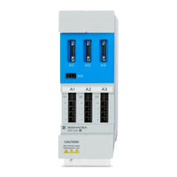
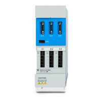
Power/Axes & Axes Modules
Brand:
SIGMATEK
| Category:
Control Unit
| Size: 4 MB
Table of Contents
Size
2
Table of Contents
4
Introduction
11
Target Group/Purpose of this Operating Manual
11
Important Reference Documentation
11
Contents of Delivery
12
General Instructions
13
Abbreviations
13
Brief Descriptions Used
14
Available Models
14
Upon Request
14
Basic Safety Directives
15
Symbols Used
15
Disclaimer
17
General Safety Directives
18
Designated Use
20
Danger Electrical Shock
22
Safety Rules
22
Hot Surface Warning
23
Operation Modes
24
Safe State
25
Safe Position Evaluation
25
Current Evaluation
25
Safe Inputs and Outputs
25
Software/Training
26
Standards and Directives
27
Residual Risks
27
Safety of the Machine or Equipment
28
Directives
28
Norms
28
EU Conformity Declaration
29
Safety-Relevant Parameters
29
Description of Multi-Converter Systems
31
System Components
31
Concept
32
Function Power/Axis Module
33
Function Axis Module
33
Software Function
34
Safety Functions
35
Overview
35
Description of the Safety Functions
37
Stop Functions
37
SS1 - Safe Stop
37
SS2 - Safe Stop
37
STO - Safe Torque off
38
SS1 with Constant Time Delay
40
SS1 with Speed Monitoring
43
SS1 with Deceleration Monitoring
44
SS1 with SBC
45
SS2 with Constant Time Delay
50
SS2 with Speed Monitoring
52
SS2 with Deceleration Monitoring
53
Monitoring Functions
56
SOS - Safe Operation Stop
57
SLA (Safely Limited Acceleration)
61
SMA - Safe Maximum Acceleration
65
SLS - Safely Limited Speed
67
SLS with Activation by Delay Time
67
SLS with Activation by Low Speed
68
SLS with Delay Monitoring
69
SMS - Safe Maximum Speed
73
SLP - Safely Limited Position
75
SLI - Safely Limited Increment
79
SDI - Safe Direction
81
SCA - Safe CAM
85
SSM - Safe Speed Monitor
86
Output Functions Per Axis
87
SBC - Safe Brake Control
88
SBT - Safe Brake Test
89
Wiring Examples Safety
94
Dual Channel Input Mapping
94
Preconditions for Safety Functions
97
Referencing the Position
97
Encoder Verification
97
Technical Data
98
DC-Link Circuit
98
Auxiliary Voltage
98
Axis/Motor Connection
99
Safe/Capture Inputs
99
Signal Output for Cross-Circuit Detection
100
Encoder Interface
101
Expanded MDP 2XXX Specifications
102
Power Supply
102
Ballast Resistance
103
Communication
103
Motor Holding Brake
103
Mechanics
104
Environmental Conditions
105
Miscellaneous
105
Mechanical Dimensions
106
Size
106
Connectors and Cables
108
Size 1 Overview
108
Size 1 Front Interfaces
108
Size 1 Top Interfaces
109
Size 1 Bottom Interfaces (Power/Axis Module)
110
Size 2 Overview
111
Size 2 Front Interfaces
111
Size 2 Top Interfaces
112
Size 2 Bottom Interfaces (Power/Axis Module)
113
Connector Layout
113
X1, X2, X3: Motor Connection
113
Pin Assignment Hiperface DSL Cable
114
Motor Temperature Cable Pin Assignment
114
X30 BG1: Power Supply (MDP 2102)
114
X30 BG1: Power Supply (MDP 2100)
115
X30 BG2: Power Supply (MDP 2200)
115
X31: Ballast Resistance (MDP 210X, MDP 2200)
115
X20: +24 V Supply
116
X21: STO Diagnostic Relays
116
X22: Safe Inputs/Capture Inputs
116
X23: Safe Inputs/Capture Inputs/Clock Signal Outputs
116
VARAN Bus (Industrial Mini I/O)
116
X11, X12 X13: Optional Encoder Module
117
Endat Cable Pin Assignment
118
Resolver Cable Pin Assignment
119
Hiperface Cable Pin Assignment
119
Biss-C Cable Pin Assignment
120
X10: Battery Terminal
120
Status Leds
121
Cable Cross Sections
122
X1, X2, X3 (Motor Connection)
122
X30 BG1 (Power Supply), X31 (Ballast Resistor), X20 (+24 V Supply)
123
X30 BG2 (Power Supply)
124
Connector)
124
Cable Lengths
125
Cable Strain Relief
126
Applicable Cable Types
126
Power Supply
127
Varan
127
DC-Link Circuit
127
Motor Cable
127
Encoder Cables
128
Configuration and Setting
129
Training Opportunities
129
Electrical Configuration
130
Motor Selection
130
Internal
130
With Encoder Interface
130
Supplementary Specifications Encoder
131
Electrical Installation
132
Fuse
132
Guidelines for Installation and Wiring
132
Protective Earth Connection
133
Protective Earth Connection between Multiple Modules
134
Ground Fault Interrupter
135
Shield Connector Clamps
136
Guidelines for Correct EMC Control Cabinet Construction
136
Configuration of the Control Cabinet
137
Wiring
137
Using Cooling Devices
138
Pre-Start Check List
140
Safety
140
Assembly/Installation
142
Check Contents of Delivery
142
Safety Guideline
142
Position of the Mounting Holes
143
Size
143
Mounting and Connecting the MDP and MDD Modules
145
Connecting DC-Link and VARAN
146
Installing Universal Encoder Modules
147
Monitoring and Warning Functions
148
Error Configuration
148
Over Temperature Protection
148
Motor Overload Protection
148
Decommissioning and Maintenance
149
Repairing Individual Devices
149
Maintenance
149
Exchanging the Fan
149
Encoder Exchange
151
Forming
151
Forming of Capacitors
152
Exchange of MDD
153
Restarting
153
Transport/Storage
154
Packaging, Transport and Storage Specifications
154
Maintenance
156
Repair
156
Accessories
157
Cable Type Key
157
Motor Cables
157
Encoder Cables
159
Encoder Modules
160
Replacement Fan
160
Disposal
161
Advertisement
SIGMATEK DIAS-Drive 2000 Operating Manual (101 pages)
Brand:
SIGMATEK
| Category:
Control Unit
| Size: 7 MB
Table of Contents
Size
2
Table of Contents
4
1 Introduction
10
Target Group/Purpose of this Operating Manual
10
Important Reference Documentation
10
Contents of Delivery
11
2 General Instructions
12
Abbreviations
12
Brief Descriptions Used
13
Available Models
13
Upon Request
13
3 Basic Safety Guidelines
14
Symbols Used
14
Disclaimer
16
General Safety Guidelines
17
Designated Use
19
Danger Electrical Shock
21
Safety Rules
21
Hot Surface Warning
22
Operation Modes
22
Safe State
22
Safe Inputs and Outputs
23
Software/Training
23
4 Standards and Guidelines
24
Residual Risks
24
Safety of the Machine or Equipment
25
Guidelines
25
Norms
25
EU Conformity Declaration
26
Safety-Relevant Parameters
26
5 Description of Multi-Converter Systems
27
System Components
27
Concept
28
Function Power/Axis Module
29
Function Axis Module
29
Software Function
29
6 Safety Functions
31
Overview
31
Description of the Safety Functions
32
Stop Functions
32
Safe Torque off (STO)
32
Safe Stop 1 (SS1)
33
Wiring Examples Safety
34
7 Technical Data
37
DC-Link Circuit
37
Auxiliary Voltage
37
Axis/Motor Connection
38
Safe/Capture Inputs
38
Signal Output for Cross-Circuit Detection
38
Encoder Interface
39
Expanded MDP 2XXX Specifications
40
Power Supply
40
Ballast Resistance
40
Communication
41
Motor Holding Brake
41
Mechanics
41
Environmental Conditions
42
Miscellaneous
42
8 Mechanical Dimensions
43
Size
43
Size
45
9 Connectors and Cables
46
Size 1 Overview
46
Size 1 Front Interfaces
46
Size 1 Top Interfaces
47
Size 1 Bottom Interfaces (Power/Axis Module)
48
Size 2 Overview
49
Size 2 Front Interfaces
49
Size 2 Top Interfaces
50
Size 2 Bottom Interfaces (Power/Axis Module)
51
Size 3 Overview
52
Size 3 Front Interfaces
52
Size 3 Top Interfaces
53
Size 3 Bottom Interfaces (Power/Axis Module)
54
Connector Layout
54
X1, X2 X3: Motor Connection
54
Pin Assignment Hiperface DSL Cable
55
Motor Temperature Cable Pin Assignment
55
X30 BG1: Power Supply (MDP 2102)
55
X30 BG1: Power Supply (MDP 2100)
56
X30 BG2: Power Supply (MDP 2200)
56
X30 BG3: Power Supply (MDP 2300)
56
X31: Ballast Resistance (MDP 210X, MDP 2200, MDP 2300)
57
X20: +24 V Supply
57
X21: STO Diagnostic Relays
57
X22: Safe Inputs/Capture Inputs
57
X23: Safe Inputs/Capture Inputs/Clock Signal Outputs
58
VARAN Bus (Industrial Mini I/O)
58
X11, X12 X13: Optional Encoder Module
59
Endat Cable Pin Assignment
60
Resolver Cable Pin Assignment
61
Hiperface Cable Pin Assignment
61
X10: Battery Terminal
62
Status Leds
63
Cable Cross Sections
64
X1, X2, X3 (Motor Connection)
64
X30 BG1 (Power Supply), X31 (Ballast Resistor), X20 (+24 V Supply)
65
X30 BG2 (Power Supply)
66
X30 BG3 (Power Supply)
66
X21 (STO Diagnostic Relay), X22 (Inputs), X23 (Signal Output), X10 (Battery Connector)
67
Cable Lengths
68
Cable Strain Relief
68
Applicable Cable Types
69
Power Supply
69
Varan
69
DC-Link Circuit
70
Motor Cable
70
Encoder Cables
70
10 Configuration and Setting
71
Training Opportunities
71
11 Electrical Configuration
72
Motor Selection
72
Internal
72
With Encoder Interface
72
Supplementary Specifications Encoder
73
Electrical Installation
73
Fuse
74
Guidelines for Installation and Wiring
74
Protective Earth Connection
75
Protective Earth Connection between Multiple Modules
76
Ground Fault Interrupter
77
Shield Connector Clamps
78
Guidelines for Correct EMC Control Cabinet Construction
78
Configuration of the Control Cabinet
79
Wiring
79
Using Cooling Devices
80
Pre-Start Check List
82
12 Assembly/Installation
83
Check Contents of Delivery
83
Safety Guideline
83
Position of the Mounting Holes
84
Size
84
Size
85
Mounting and Connecting the MDP and MDD Modules
85
Connecting DC-Link and VARAN
87
Installing Universal Encoder Modules
87
13 Monitoring and Warning Functions
89
Error Configuration
89
Over Temperature Protection
89
Motor Overload Protection
89
14 Decommissioning and Maintenance
90
Repairing Individual Devices
90
Maintenance
90
Exchanging the Fan
90
Forming
91
Forming of Capacitors
92
Restarting
93
15 Transport/Storage
94
Packaging, Transport and Storage Specifications
94
16 Maintenance
95
Repair
95
17 Accessories
96
Cable Type Key
96
Motor Cables
96
Encoder Cables
98
Encoder Modules
99
Replacement Fan
99
18 Disposal
100
Advertisement
Related Products
Sigmatek DC 061-1
SIGMATEK DM 167
SIGMATEK S-DIAS DM 821
SIGMATEK DI 169
SIGMATEK DC 102
SIGMATEK DM 046
SIGMATEK DC 101
SIGMATEK DC 104
SIGMATEK S-DIAS DC 064
SIGMATEK DI 200
SIGMATEK Categories
Control Unit
I/O Systems
Touch terminals
Control Panel
Computer Hardware
More SIGMATEK Manuals
Login
Sign In
OR
Sign in with Facebook
Sign in with Google
Upload manual
Upload from disk
Upload from URL