
Related Manuals for SIGMATEK DC 061-1


Summary of Contents for SIGMATEK DC 061-1
- Page 1 DC 061-1 S-DIAS Axis Module Instruction Manual Date of creation: 26.07.2016 Version date: 05.12.2023 Article number: 20-014-061-1E...
- Page 2 (print, photocopy, microfilm or in any other process) without the express permission. We reserve the right to make changes in the content without notice. The SIGMATEK GmbH & Co KG is not responsi- ble for technical or printing errors in the handbook and assumes no responsibility for damages that occur through...
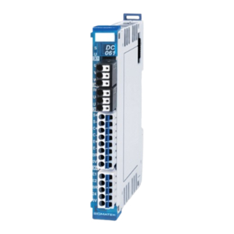
- Page 3 1 resolver input 1 holding brake The S-DIAS DC 061-1 axis module is used to control a brushless DC motor with a 48-Volt supply voltage and phase current of up to 6 A. A resolver input is available for position feedback. A 24 V output for con- necting a holding brake is provided.
-
Page 4: Table Of Contents
DC 061-1 S-DIAS AXIS MODULE Contents Introduction ................6 Target Group/Purpose of this Operating Manual ...... 6 Important Reference Documentation ......... 6 Contents of Delivery ..............6 Basic Safety Guidelines ............7 Symbols Used ................7 Disclaimer ..................9 General Safety Directives ............10 Designated Use ................ - Page 5 Applicable Connectors ............... 29 Label Field ................... 31 Wiring ..................32 Wiring Example ................32 Notes .................... 33 Wiring SIGMATEK Motors ............34 Servo Motor and Encoder Cables ..........35 9.4.1 Motor Cable AKM with M23 Round Connectors ........ 36 9.4.2 Motor Cable AKM with Y-Tec Connectors ........
- Page 6 DC 061-1 S-DIAS AXIS MODULE 9.4.3 Motor Cable AKM with Molex Connectors ......... 42 9.4.4 Encoder Cable with M23 Round Connectors ........45 9.4.5 Encoder Cable with Y-Tec Connectors ..........46 9.4.6 Encoder Cable with Molex Connectors ..........48 10 Motor Overload Protection ............50 11 Additional Safety Information ..........51...
- Page 7 S-DIAS AXIS MODULE DC 061-1 16 Storage ................... 69 17 Maintenance ................70 17.1 Service ..................70 17.2 Repair ................... 70 18 Disposal ................. 70 05.12.2023 Page 5...
-
Page 8: Introduction
General knowledge of automation technology is required. Further help and training information, as well as the appropriate accessories can be found on our website www.sigmatek-automation.com. Our support team is happily available to answer your questions. Please see our website for our hotline number and business hours. -
Page 9: Basic Safety Guidelines
S-DIAS AXIS MODULE DC 061-1 Basic Safety Guidelines Symbols Used The following symbols are used in the operator documentation for warning and danger messages, as well as informational notes: DANGER Danger indicates that death or serious injury will occur, if the speci- fied measures are not taken. - Page 10 DC 061-1 S-DIAS AXIS MODULE DANGER • Electrical voltage • Tension électrique CAUTION Danger for ESD-sensitive components. Les signes de danger pour les composants sensibles aux décharges électrostatiques. INFORMATION Information Provides important information on the product, handling or relevant sections of the documentation, which require atten- tion.
-
Page 11: Disclaimer
It does not guarantee properties under the warranty. Please thoroughly read the corresponding documents and this operat- ing manual before handling a product. SIGMATEK GmbH & Co KG is not liable for damages caused through, non-compliance with these instructions or applicable regulations. -
Page 12: General Safety Directives
DC 061-1 S-DIAS AXIS MODULE General Safety Directives The Safety Directives in the other sections of this operating manual must be observed. These instructions are visually emphasized by symbols. INFORMATION According to EU Directives, the operating manual is a component of a product. - Page 13 S-DIAS AXIS MODULE DC 061-1 CAUTION Handle the device with care and do not drop or let fall. Prevent foreign bodies and fluids from entering the device. The device must not be opened! Manipulez l’appareil avec précaution et ne le laissez pas tomber.
-
Page 14: Designated Use
The Safety functions implemented in the product are designed for use with safety applica- tions in a SIGMATEK control and meet the required conditions for safe operation according to SIL 3, HFT 1 n compliance with EN IEC 62061 and according to PL e, Kat. 4 in compli- ance with EN ISO 13849-1. -
Page 15: Software/Training
S-DIAS AXIS MODULE DC 061-1 prévue. Non-designated use consists of: • any changes made to the module or the use of damaged modules. • use of the module inconsistent with the technical margins de- scribed in this operating manual or the specifications defined in the technical data. -
Page 16: Security
DC 061-1 S-DIAS AXIS MODULE IT Security S-DIAS safety modules were developed for integration into a network protected against unauthorized access. For example, the following dangers can affect the network: • Unauthorized access • Data manipulation • and many other IT security violations It is the responsibility of the operator to protect the safe connection between S-DIAS mod- ules against unauthorized access. -
Page 17: Standards And Directives
S-DIAS AXIS MODULE DC 061-1 Standards and Directives Residual Risks CAUTION The following residual risks for the product must be included in the system integrator's risk assessment: • Release of non-environmentally safe substances, emissions and unusual temperatures • Possible effects of information technology devices Les risques résiduels suivants pour le produit doivent être inclus dans... -
Page 18: Functional Safety Standards
EN ISO 13849-2 - Safety of machinery — Safety-related parts of control systems — Part 2: Validation 4.3.2 EU Conformity Declaration EU Declaration of Conformity The product DC 061-1 conforms to the following European directives: • 2006/42/EG Machine Directive • 2014/30/EU Electromagnetic Compatibility (EMC Directive) •... -
Page 19: Type Plate
S-DIAS AXIS MODULE DC 061-1 Type Plate HW: Hardware version SW: Software version 05.12.2023 Page 17... -
Page 20: Technical Data
DC 061-1 S-DIAS AXIS MODULE Technical Data Motor Driver Specifications Type brushless DC Operating voltage +24-55 V Maximum continuous current Maximum peak current (10 sec) 15 A Controller frequency 16 kHz PWM frequency 16 kHz Overload protection short circuit cutoff... -
Page 21: Enable Inputs Specifications
SIGMATEK provides a regen resistor of 15 Ω/50 W (20-014-061-Z1) for the DC 061-1. For most applications this resistor is sufficient. There- fore, the parameter P49 G-RBAL is set to 15 Ω on the standard parameter files of the 48V motors. - Page 22 DC 061-1 S-DIAS AXIS MODULE WARNING Hot surface warning! Physical contact poses a burn hazard! During operation, the surface of the brake resistor can become very hot and remain so for some time after operation. Avertissement de surface chaude Le contact physique pose un risque de brûlure Pendant le fonctionnement, la surface de la résistance de freinage...
-
Page 23: Electrical Requirements
S-DIAS AXIS MODULE DC 061-1 Electrical Requirements Power supply +24 V (X4) +18-30 V, Class 2 Current consumption of the load-dependent (holding brake) +24 V supply Supply voltage motor (X2) +24-55 V DC Switching threshold for motor minimum 18 V... - Page 24 DC 061-1 S-DIAS AXIS MODULE Use wires only that are allowed for at least 75 °C! There is no motor thermostat evaluation in the motor output stage. Incorrectly set parameter or incorrect wiring can lead to destruction of the motor. In particular, motor currents and the I2T settings (A-I2TT, A- I2TERR) must be monitored, which can be parameterized in the DIAS- Drive Editor via the LASAL Class 2 tool.
- Page 25 S-DIAS AXIS MODULE DC 061-1 05.12.2023 Page 23...
-
Page 26: Miscellaneous
DC 061-1 S-DIAS AXIS MODULE Miscellaneous Article number 20-014-061-1 20-014-061-1X (polymer coated printed circuit board) Standard UL 508C (E336350) Approvals , CE, TÜV-Austria EG-type-examined Mission time 20 years Reaction time see chapter "Reaction and Turn-off Time" in the Safety System Handbook... -
Page 27: Mechanical Dimensions
S-DIAS AXIS MODULE DC 061-1 Mechanical Dimensions 05.12.2023 Page 25... -
Page 28: Connector Layout
With the layout, an M-ROFF of 270 °C results. M-ROFF is the angle offset between the mechanical 0° position of the encoder and the elec- trical 0° position. SIGMATEK uses the angle as the 0° position when the voltage space pointer is impressed at 0°, so that the current space pointer points to 270°. -
Page 29: Sigmatek
S-DIAS AXIS MODULE DC 061-1 SIGMATEK INFORMATION Both holding brake outputs (BR) are internally connected in parallel. The holding brake can therewith be optionally connected to X3 (pin 7- Pin 8) or X4 (pin 3-pin 5). When using motors with even pole pair number (e.g. AKM31K 4 pole pairs) this results in a feedback offset of 180°. -
Page 30: Status Leds
DC 061-1 S-DIAS AXIS MODULE Status LEDs Module Status green module active no supply available BLINKING (5 Hz) no communication User yellow can be set from the application (e.g. the module LED can be set to blinking through the visuali-... -
Page 31: Applicable Connectors
S-DIAS AXIS MODULE DC 061-1 Applicable Connectors X1, X2: Weidmüller socket connector with spring terminal (included in delivery) X3, X4: Phoenix connectors with spring terminals (included in delivery) The spring terminals are suitable connecting ultrasonically compacted (ultrasonically weld- ed) strands. - Page 32 DC 061-1 S-DIAS AXIS MODULE Connections Phoenix Plug Connectors: Stripping length: 10 mm Plug-in direction: parallel to conductor axis or to PCB Conductor cross section, rigid: 0.2-1.5 mm Conductor cross section, flexible: 0.2-1.5 mm Conductor cross section, ultrasonically compacted: 0.2-1.5 mm...
-
Page 33: Label Field
S-DIAS AXIS MODULE DC 061-1 Label Field Manufacturer Weidmüller Type MF 10/5 CABUR MC NE WS Weidmüller article number 1854510000 Compatible printer Weidmüller Type Printjet Advanced 230V Weidmüller article number 1324380000 05.12.2023 Page 31... -
Page 34: Wiring
DC 061-1 S-DIAS AXIS MODULE Wiring Wiring Example Page 32 05.12.2023... -
Page 35: Notes
S-DIAS AXIS MODULE DC 061-1 Notes The following installation instructions must be observed: • The DIN rail must have a proper ground connection. • A shielded cable must be used for wiring the resolver. For a resolver - encoder, the use of a shielded and twisted cable is recommended. -
Page 36: Wiring Sigmatek Motors
DC 061-1 S-DIAS AXIS MODULE Wiring SIGMATEK Motors with SIGMATEK resolver and motor ca- bles Page 34 05.12.2023... -
Page 37: Servo Motor And Encoder Cables
Fixed installation: 7,5 x D / Flexible use: 10 x D Resolver cable 4 x 2 x 0,18 mm² - Ø 6,4 mm: Fixed installation: 4 x D / Flexible use: 7,5 x D Overview cables SIGMATEK motors M23 specifications (0): Power cable + brake... -
Page 38: Motor Cable Akm With M23 Round Connectors
DC 061-1 S-DIAS AXIS MODULE 9.4.1 Motor Cable AKM with M23 Round Connectors With Holding Brake Length M061E-10-1-015-0-0 1.5 m M061E-10-1-030-0-0 3.0 m M061E-10-1-050-0-0 5.0 m M061E-10-1-100-0-0 10.0 m Motor cable, shielded, suitable for drag chains, with round plug on motor side and wire end sleeves on module side and 6.3 mm flat connector for the shield and PE. - Page 39 S-DIAS AXIS MODULE DC 061-1 INFORMATION The Shielding/PE connections of the motor cable must be grounded on the module side via the 6.3 mm flat connector provided on the respec- tive cables. Without Holding Brake Length M061E-10-0-015-0-0 1.5 m M061E-10-0-030-0-0 3.0 m...
- Page 40 DC 061-1 S-DIAS AXIS MODULE INFORMATION The Shielding/PE connections of the motor cable must be grounded on the module side via the 6.3 mm flat connector provided on the respec- tive cables. Page 38 05.12.2023...
-
Page 41: Motor Cable Akm With Y-Tec Connectors
S-DIAS AXIS MODULE DC 061-1 9.4.2 Motor Cable AKM with Y-Tec Connectors With Holding Break Length M061E-10-1-015-1-0 1.5 m M061E-10-1-030-1-0 3.0 m M061E-10-1-050-1-0 5.0 m M061E-10-1-100-1-0 10.0 m Motor cable, shielded, suitable for drag chains, with round plug on motor side and wire end sleeves on module side and 6.3 mm flat connector for the shield and PE. - Page 42 DC 061-1 S-DIAS AXIS MODULE INFORMATION The Shielding/PE connections of the motor cable must be grounded on the module side via the 6.3 mm flat connector provided on the respec- tive cables. Without Holding Break Length M061E-10-0-015-1-0 1.5 m M061E-10-0-030-1-0 3.0 m...
- Page 43 S-DIAS AXIS MODULE DC 061-1 INFORMATION The Shielding/PE connections of the motor cable must be grounded on the module side via the 6.3 mm flat connector provided on the respec- tive cables. 05.12.2023 Page 41...
-
Page 44: Motor Cable Akm With Molex Connectors
DC 061-1 S-DIAS AXIS MODULE 9.4.3 Motor Cable AKM with Molex Connectors With Holding Brake Length M061E-10-1-015-3-0 1.5 m M061E-10-1-030-3-0 3.0 m M061E-10-1-050-3-0 5.0 m M061E-10-1-100-3-0 10.0 m Motor cable, shielded, suitable for drag chains, with plug on motor side and wire end sleeves on module side and 6.3 mm flat connector for the shield and PE. - Page 45 S-DIAS AXIS MODULE DC 061-1 INFORMATION The Shielding/PE connections of the motor cable must be grounded on the module side via the 6.3 mm flat connector provided on the respec- tive cables. Without Holding Brake Length M061E-10-0-015-3-0 1.5 m M061E-10-0-030-3-0 3.0 m...
- Page 46 DC 061-1 S-DIAS AXIS MODULE INFORMATION The Shielding/PE connections of the motor cable must be grounded on the module side via the 6.3 mm flat connector provided on the respec- tive cables. With increased interference, it may be necessary to also connect the motor cable on the motor side.
-
Page 47: Encoder Cable With M23 Round Connectors
S-DIAS AXIS MODULE DC 061-1 9.4.4 Encoder Cable with M23 Round Connectors Name Encoder type Length Outer diameter F-RO-061-015-0-00 Resolver 1.5 m 6.4 mm F-RO-061-030-0-00 Resolver 6.4 mm F-RO-061-050-0-00 Resolver 6.4 mm F-RO-061-100-0-00 Resolver 10 m 6.4 mm Encoder cable, shielded, suitable for drag chains, with round plug on motor side and wire end sleeves on module side and 6.3 mm flat connector for the shield. -
Page 48: Encoder Cable With Y-Tec Connectors
DC 061-1 S-DIAS AXIS MODULE 9.4.5 Encoder Cable with Y-Tec Connectors Name Encoder type Length Outer diameter F-RO-061-015-1-00 Resolver 1.5 m 6.4 mm F-RO-061-030-1-00 Resolver 6.4 mm F-RO-061-050-1-00 Resolver 6.4 mm F-RO-061-100-1-00 Resolver 10 m 6.4 mm Encoder cable, shielded, suitable for drag chains, with round plug on motor side and wire end sleeves on module side and 6.3 mm flat connector for the shield. - Page 49 S-DIAS AXIS MODULE DC 061-1 INFORMATION The Shielding/PE connections of the encoder cable shielding must be grounded on the module side via the 6.3 mm flat connector provided on the respective cables. 05.12.2023 Page 47...
-
Page 50: Encoder Cable With Molex Connectors
DC 061-1 S-DIAS AXIS MODULE 9.4.6 Encoder Cable with Molex Connectors Name Encoder type Length Outer diameter F-RO-061-015-3-00 Resolver 1.5 m 6.4 mm F-RO-061-030-3-00 Resolver 6.4 mm F-RO-061-050-3-00 Resolver 6.4 mm F-RO-061-100-3-00 Resolver 10 m 6.4 mm Encoder cable, shielded, suitable for drag chains, with plug on motor side and wire end sleeves on module side and 6.3 mm flat connector for the shield. - Page 51 S-DIAS AXIS MODULE DC 061-1 INFORMATION The Shielding/PE connections of the encoder cable shielding must be grounded on the module side via the 6.3 mm flat connector provided on the respective cables. With increased interference, it may be necessary to also connect en- coder cable on the motor side.
-
Page 52: Motor Overload Protection
DC 061-1 S-DIAS AXIS MODULE 10 Motor Overload Protection Equipment does not incorporate motor overload protection. External or remote overload protection in accordance with National Electrical Code and any additional local codes must be provided in the field. Motor overtemperature sensing is not provided by the drive. -
Page 53: Additional Safety Information
DC 061-1 11 Additional Safety Information The Safety function “STO” is an integrated part of the DC 061-1. It meets all necessary requirements for safe operation in SIL 3 according to EN IEC 62061 and in compliance with PL e. Cat. 4 in accordance with EN ISO 13849-1. - Page 54 DC 061-1 S-DIAS AXIS MODULE Correct EMC installation is also included in the designated use. Pour votre propre sécurité et celle des autres, les modules de sécurité ne doivent être utilisés qu’à des fins prévues. Une installation CEM correcte est également incluse dans l’utilisation prevue.
- Page 55 S-DIAS AXIS MODULE DC 061-1 DANGER Failure to follow the above safety measures can lead to severe injuries. Le non-respect des mesures de sécurité ci-dessus peut entraîner des blessures graves. • Only trained personnel are authorized to install the "safe re- start lock"...
- Page 56 DC 061-1 S-DIAS AXIS MODULE l'extérieur de l'armoire électrique. Eviter les courts-circuits ou les courts-circuits croisés dans les lignes de signalisation ! Voir EN ISO 13849 • Si des forces externes influencent les axes utilisés avec la fonction de sécurité STO (par ex. charge suspendue), des mesures supplémentaires doivent être prises (par ex.
-
Page 57: Sto
S-DIAS AXIS MODULE DC 061-1 11.1 STO The DC 061-1 supports the safety functions STO (Safe Torque Off) and meets the re- quirements for Category 4 Performance Level "e" according to EN ISO 13849-1 and SILCL 3 according to EN IEC 62061. -
Page 58: Function Test
DC 061-1 S-DIAS AXIS MODULE 11.3 Function Test WARNING The safety function test is required to ensure correct operation. The entire safety circuit must be tested for full functionality. Tests must be performed at the following times: • After installation •... -
Page 59: Wiring Examples
S-DIAS AXIS MODULE DC 061-1 12 Wiring Examples In the following sub chapters, wiring examples are provided. It must be ensured that all constructive measures etc. are complied with and applied in order to fulfill the requirements of the category used. - Page 60 DC 061-1 S-DIAS AXIS MODULE Page 58 05.12.2023...
-
Page 61: Performance Level E, Category 3 & Silcl 3 - Safety Plc
S-DIAS AXIS MODULE DC 061-1 12.2 Performance Level e, Category 3 & SILCL 3 – Safety PLC To meet the requirements of safety category 3, performance level "e" for EN 13849-1 and SILCL 3 according to EN IEC 62061, an error-proof output of a safety PLC must be used. - Page 62 DC 061-1 S-DIAS AXIS MODULE Page 60 05.12.2023...
-
Page 63: Performance Level E, Category 4 Or Silcl 3 - Conventional
S-DIAS AXIS MODULE DC 061-1 12.3 Performance Level e, Category 4 or SILCL 3 – Conventional To meet the requirements of safety category 4, performance level "e" for EN ISO 13849-1 and SILCL 3 according to EN IEC 62061, the placement of the lines must comply with EN ISO 13849-2, table D.4 (separate placement, prohibiting of error via short circuits between... - Page 64 DC 061-1 S-DIAS AXIS MODULE Page 62 05.12.2023...
-
Page 65: Performance Level D, Category 2 Or Sil 2 - Conventional
S-DIAS AXIS MODULE DC 061-1 12.4 Performance Level d, Category 2 or SIL 2 – Conventional This involves 1-channel wiring, whereby the Enable inputs are tested separately. Here, no cross-circuit detection is possible. 05.12.2023 Page 63... - Page 66 DC 061-1 S-DIAS AXIS MODULE Page 64 05.12.2023...
-
Page 67: Assembly/Installation
S-DIAS AXIS MODULE DC 061-1 13 Assembly/Installation 13.1 Check Contents of Delivery Ensure that the contents of the delivery are complete and intact. See chapter Contents of Delivery. INFORMATION On receipt and before initial use, check the device for damage. If the device is damaged, contact our customer service and do not install the device in your system. -
Page 68: Mounting
DC 061-1 S-DIAS AXIS MODULE 13.2 Mounting The S-DIAS modules are designed for installation into the control cabinet. To mount the modules a DIN-rail is required. The DIN rail must establish a conductive connection with the back wall of the control cabinet. The individual S-DIAS modules are mounted on the DIN rail as a block and secured with latches. - Page 69 S-DIAS AXIS MODULE DC 061-1 Recommended minimum distances of the S-DIAS modules to the surrounding components or control cabinet wall: a, b, c … distances in mm (inches) 05.12.2023 Page 67...
-
Page 70: Supported Cycle Times
DC 061-1 S-DIAS AXIS MODULE 14 Supported Cycle Times The DC 061 can be accessed via the S-DIAS bus with different bus cycle times. 14.1 Cycle Times below 1 ms (in µs) 14.2 Cycle Times equal to or higher than 1 ms (in ms) Page 68 05.12.2023... -
Page 71: Transport/Storage
S-DIAS AXIS MODULE DC 061-1 15 Transport/Storage INFORMATION This device contains sensitive electronics. During transport and stor- age, high mechanical stress must therefore be avoided. For storage and transport, the same values for humidity and vibration as for operation must be maintained! Temperature and humidity fluctuations may occur during transport. -
Page 72: Maintenance
DC 061-1 S-DIAS AXIS MODULE 17 Maintenance INFORMATION During maintenance as well as servicing, observe the safety instruc- tions from chapter Basic Safety Directives. 17.1 Service This product was constructed for low-maintenance operation. 17.2 Repair INFORMATION In the event of a defect/repair, send the device with a detailed error description to the address listed at the beginning of this document. - Page 73 S-DIAS AXIS MODULE DC 061-1 Documentation Changes Change date Affected Chapter Note page(s) 06.02.2017 1.6 Electrical Requirements Added warning 19.05.2017 4.1 Wiring example Diagram replaced 17.08.2017 1.8 Environmental Conditions Added operating conditions 3.4 Applicable Connectors Added sleeve length Added info regarding ultrasonically welded strands 18.10.2017...
- Page 74 DC 061-1 S-DIAS AXIS MODULE 25.11.2019 2.8 Environmental Conditions Functional security added 5.2 Wiring AKM Motors Graphic corrected 7.3 Safety-Relevant Parame- Updated and expanded chapter ters Additional Safety Information SS1 removed 16.12.2019 4.2 Kollmorgen Info box added 20.01.2020 2.1 Motor Driver Specifica-...
- Page 75 S-DIAS AXIS MODULE DC 061-1 05.12.2023 Page 73...
Need help?
Do you have a question about the DC 061-1 and is the answer not in the manual?
Questions and answers