
Related Manuals for Vega VEGAPOINT 23


Summary of Contents for Vega VEGAPOINT 23
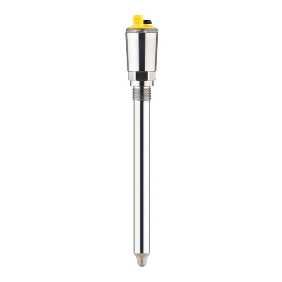
- Page 1 Operating Instructions Capacitive level switch VEGAPOINT 23 Three-wire: IO-Link, transistor Document ID: 62324...
-
Page 2: Table Of Contents
Sensor parameter adjustment ..................31 Setup with PC/notebook (Bluetooth) ................... 32 Preparations ........................32 Connecting ........................32 Sensor parameter adjustment ..................33 10 Diagnostics and servicing ....................34 10.1 Maintenance ........................34 10.2 Rectify faults ........................34 VEGAPOINT 23 • Three-wire: IO-Link, transistor... - Page 3 13.1 Technical data ........................ 43 13.2 Device communication IO-Link ..................46 13.3 Dimensions ........................52 13.4 Industrial property rights ....................53 13.5 Licensing information for open source software ............. 53 13.6 Trademark ........................53 Editing status: 2024-07-22 VEGAPOINT 23 • Three-wire: IO-Link, transistor...
-
Page 4: About This Document
Symbols used Document ID This symbol on the front page of this instruction refers to the Docu- ment ID. By entering the Document ID on www.vega.com you will reach the document download. Information, note, tip: This symbol indicates helpful additional infor- mation and tips for successful work. -
Page 5: For Your Safety
During work on and with the device, the required personal protective equipment must always be worn. Appropriate use The VEGAPOINT 23 is a sensor for point level detection. You can find detailed information about the area of application in chapter "Product description". Operational reliability is ensured only if the instrument is properly used according to the specifications in the operating instructions manual as well as possible supplementary instructions. -
Page 6: Safety Instructions For Ex Areas
Safety instructions for Ex areas For applications in hazardous areas (Ex), only devices with corre- sponding Ex approval may be used. Observe the Ex-specific safety instructions. These are an integral part of the device documentation and are enclosed with every device with Ex approval. VEGAPOINT 23 • Three-wire: IO-Link, transistor... -
Page 7: Product Description
Information sheet "PINs and Codes" (with Bluetooth versions) with: – Bluetooth access code Information: Optional instrument features are also described in this instructions. The respective scope of delivery results from the order specification. Constituent parts The VEGAPOINT 23 consists of the components: • Housing with integrated electronics • Process fitting • Plug (optional) Fig. -
Page 8: Principle Of Operation
Open the VEGA Tools app and enter the serial number under "Documentation". Principle of operation The VEGAPOINT 23 is a capacitive point level sensor for point level Application area detection It is designed for industrial use in all areas of process technology and can be used on site in water-based liquids without adjustment of the medium. -
Page 9: Packaging, Transport And Storage
Transport Transport must be carried out in due consideration of the notes on the transport packaging. Nonobservance of these instructions can cause damage to the device. Reduced effective range with M12 x 1 plug stainless steel (closed full metal housing), see chapter "Technical Data" VEGAPOINT 23 • Three-wire: IO-Link, transistor... -
Page 10: Accessories
The instructions for the listed accessories can be found in the down- load area on our homepage. Threaded and hygienic Various threaded and hygienic sockets are available for devices with socket threaded version. You can find further information in chapter "Technical Data". VEGAPOINT 23 • Three-wire: IO-Link, transistor... -
Page 11: Mounting
• Abrasion and mechanical influences Switching point The VEGAPOINT 23 can be mounted in any position. The instrument must be mounted in such a way that the sensor is at the height of the requested switching point. VEGAPOINT 23 • Three-wire: IO-Link, transistor... - Page 12 (e.g. through cleaning processes) and on cooled or heated vessels. Handling The level switch is a measuring device for stationary screw mounting and must be treated accordingly. Damage to the measuring tip will destroy the instrument. VEGAPOINT 23 • Three-wire: IO-Link, transistor...
-
Page 13: Mounting Instructions
For this reason, do not use an overly long extension tube for VEGAPOINT 23, but check if you can mount a short level switch on the side of the vessel in horizontal position. - Page 14 4 Mounting Fig. 5: Lateral suppot of VEGAPOINT 23 VEGAPOINT 23 • Three-wire: IO-Link, transistor...
-
Page 15: Connecting To Power Supply
EN 61326-1 for industrial areas, shielded cable should be used. Connecting Instrument versions Fig. 6: Instrument versions Device version with housing 316L and plastic Device version with full metal housing 316L 360° status indication VEGAPOINT 23 • Three-wire: IO-Link, transistor... -
Page 16: Wiring Plan
Contact, plug connector Function/Polarity Voltage supply/+ Transistor output 2 Voltage supply/- Transistor output 1/IO-Link Switch-on phase After switching on, the device first carries out a self-test in which the function of the electronics is checked. The current measured value is then output on the signal cable. VEGAPOINT 23 • Three-wire: IO-Link, transistor... -
Page 17: Access Protection
It can't be changed. The emergency device code can also be found on the supplied information sheet "Ac- cess protection". If this document is lost, the emergency device code can be retrieved from your personal contact person after legitimation. VEGAPOINT 23 • Three-wire: IO-Link, transistor... -
Page 18: Storing The Codes In Myvega
"PINs and Codes". This greatly simplifies the use of additional adjust- ment tools, as all Bluetooth access and device codes are automati- cally synchronized when connected to the "myVEGA" account VEGAPOINT 23 • Three-wire: IO-Link, transistor... -
Page 19: Setup
NAMUR NE 107. Coverage 360° status indi- cation Switching status Switching status Output 1 Output 2 Covered open closed Green Uncovered closed open Yellow Fault open open (Covered/Uncov- ered) Default setting Switching status of output 1 VEGAPOINT 23 • Three-wire: IO-Link, transistor... -
Page 20: Menu Overview
Output Transistor function (P-N) Switching output Function output (OU1) Dry run protection/MIN (HNC) Switching point (SP1) 65 % Reset point (RP1) 67 % Switching delay (DS1) 0.5 s Reset delay (DR1) 0.5 s Only for "User-defined" application VEGAPOINT 23 • Three-wire: IO-Link, transistor... -
Page 21: Parameter Adjustment
Upper and lower case letters from A … Z • Numbers from 0 … 9 • Special characters and blanks Application In this menu item you can select the application. You can choose from the following applications: Only DTM adjustment VEGAPOINT 23 • Three-wire: IO-Link, transistor... - Page 22 Individual signalling If you have selected "Individual signaling", you can select the respec- tive LED colour separately for the following switching states. • Fault • Switching output • Operating status The following colours are available: VEGAPOINT 23 • Three-wire: IO-Link, transistor...
- Page 23 Opener = FNC (Window Normally Closed) Function output 2 (OU2) In this menu item you can set the function of the two outputs indepen- dently of each other. The selection options are the same as in output 1. VEGAPOINT 23 • Three-wire: IO-Link, transistor...
- Page 24 Window High (FH) and Window Low (FL). If the measured variable leaves the window, the output returns to its previous state. If the measured variable moves within the window, the state of the output does not change. VEGAPOINT 23 • Three-wire: IO-Link, transistor...
- Page 25 The setting is a degree for the sensitivity of the sensor tip. Reset point (RP1) The reset point (RP) controls the sensitivity of the sensor when the sensor tip becomes free. The percentage defines the upper range limit of the hysteresis. The setting is a degree for the sensitivity of the sensor tip. VEGAPOINT 23 • Three-wire: IO-Link, transistor...
- Page 26 After a reset, parameter adjustments made by the user are reset. The following reset functions are available: Restore basic settings: Resetting the parameter settings incl. spe- cial parameters to the default values of the respective device. VEGAPOINT 23 • Three-wire: IO-Link, transistor...
- Page 27 In this menu item you can retrieve the current measured values of the device. Measured values Here you can view the current coverage status of the device (covered/ uncovered). Additional measured values Here you can find additional measured values of the device. • Electronic temperature (°C/°F) VEGAPOINT 23 • Three-wire: IO-Link, transistor...
- Page 28 Click on the button "Accept simulation value". The sensor now switches to the desired simulation switching status. During simulation, the LED display flashes in the colour of the se- lected switching status. A simulation of the fault status is not possible. To cancel the simulation, click on "Terminate simulation". VEGAPOINT 23 • Three-wire: IO-Link, transistor...
- Page 29 In this menu item you can retrieve the sensor features of the device. This menu item can only be selected via PACTware with DTM. • Order texts • Instrument version • Electronics • etc. VEGAPOINT 23 • Three-wire: IO-Link, transistor...
-
Page 30: Setup With Smartphone/Tablet (Bluetooth)
• Operating system: Android 5.1 or newer • Bluetooth 4.0 LE or newer Download the VEGA Tools app from the "Apple App Store", "Goog- le Play Store" or "Baidu Store" to your smartphone or tablet. Connecting Connecting Start the adjustment app and select the function "Setup". The smart- phone/tablet searches automatically for Bluetooth-capable instru- ments in the area. -
Page 31: Sensor Parameter Adjustment
The sensor adjustment menu is divided into two halves: On the left you'll find the navigation section with the menus "Setup", "Diagnosis" and others. The selected menu item, recognisable by the colour change, is dis- played in the right half. Fig. 11: Example of an app view - Setup VEGAPOINT 23 • Three-wire: IO-Link, transistor... -
Page 32: Setup With Pc/Notebook (Bluetooth)
Enter Bluetooth access For authentication, enter in the next menu window the 6-digit code Bluetooth access code: Fig. 12: Enter Bluetooth access code VEGAPOINT 23 • Three-wire: IO-Link, transistor... -
Page 33: Sensor Parameter Adjustment
The sensor adjustment menu is divided into two halves: On the left you'll find the navigation section with the menus "Setup", "Display", "Diagnosis" and others. The selected menu item, recognisable by the colour change, is dis- played in the right half. Fig. 13: Example of a DTM view - Setup VEGAPOINT 23 • Three-wire: IO-Link, transistor... -
Page 34: Diagnostics And Servicing
24 hour service hotline Should these measures not be successful, please call in urgent cases the VEGA service hotline under the phone no. +49 1805 858550. The hotline is also available outside normal working hours, seven days a week around the clock. -
Page 35: Diagnosis, Fault Messages
The switching point (SP) must be smaller than the reset point (RP) F260 Error in the calibration Repeat device adjustment F261 Error in the instrument settings Carry out device reset Reset device to delivery status VEGAPOINT 23 • Three-wire: IO-Link, transistor... -
Page 36: Status Messages According To Ne 107
• Failure • Function check • Out of specification • Maintenance required and explained by pictographs: Fig. 14: Pictographs of the status messages Failure - red 2 Out of specification - yellow Function check - orange Maintenance required - blue VEGAPOINT 23 • Three-wire: IO-Link, transistor... - Page 37 Carry out a reset values Error in the instrument set- tings Function check Code Cause Rectification Text message C700 A simulation is active Finish simulation Simulation active Wait for the automatic end after 60 mins. VEGAPOINT 23 • Three-wire: IO-Link, transistor...
-
Page 38: Software Update
• The serial number of the instrument • A short description of the fault • Details of the medium, if applicable Print the generated instrument return form. Clean the instrument and pack it damage-proof. VEGAPOINT 23 • Three-wire: IO-Link, transistor... - Page 39 10 Diagnostics and servicing Send the printed instrument return form and possibly a safety data sheet together with the device. You will find the address for the return on the generated instrument return form. VEGAPOINT 23 • Three-wire: IO-Link, transistor...
-
Page 40: Dismount
If personal data is stored on the old device to be disposed of, delete it before disposal. If you have no way to dispose of the old instrument properly, please contact us concerning return and disposal. VEGAPOINT 23 • Three-wire: IO-Link, transistor... -
Page 41: Certificates And Approvals
Protection of the environment is one of our most important duties. That is why we have introduced an environment management system with the goal of continuously improving company environmental pro- tection. The environment management system is certified according to DIN EN ISO 14001. VEGAPOINT 23 • Three-wire: IO-Link, transistor... - Page 42 12 Certificates and approvals Help us to meet these requirements and observe the environmental instructions in the chapters "Packaging, transport and storage", "Dis- posal" of this instructions manual. VEGAPOINT 23 • Three-wire: IO-Link, transistor...
-
Page 43: Supplement
Ʋ Pipe thread, cylindrical (DIN 3852-A) G½, G¾, G1 or ISO 228-1 Ʋ Pipe thread, conical (ASME B1.20.1) ½ NPT, ¾ NPT, 1 NPT Ʋ Metric fine thread, cylindrical M24 x 1.5 Ʋ Clamp 1", 1½", 2" Ʋ Collar socket DIN 11851, PN 40 DN 25, DN 40, DN 50 VEGAPOINT 23 • Three-wire: IO-Link, transistor... - Page 44 Process conditions Process pressure Ʋ Standard version -1 … 25 bar/-100 … 2500 kPa (-14.5 … 363 psig) Ʋ Full metal version (stainless steel) -1 … 64 bar/-100 … 6400 kPa (-14.5 … 928 psig) VEGAPOINT 23 • Three-wire: IO-Link, transistor...
- Page 45 Voltage supply Operating voltage 12 … 35 V DC Max. power consumption Reverse voltage protection Integrated Max. power consumption Bluetooth interface Bluetooth standard Bluetooth 5.0 Frequency 2.402 … 2.480 GHz Max. emitted power +2.2 dBm VEGAPOINT 23 • Three-wire: IO-Link, transistor...
-
Page 46: Device Communication Io-Link
Speed: COM2 38.4 kBaud Min. cycle time 4.0 ms Length process data word: 32 Bit IO-Link Data Storage: Yes Block parameter adjustment: Yes Depending on the local conditions; with M12 x 1 plug stainless steel (closed full metal housing) effective range up to approx. 5 m (16.40 ft) Depending on the instrument version VEGAPOINT 23 • Three-wire: IO-Link, transistor... - Page 47 Device data can be parameters, identification data and diagnostic information. They are exchanged acyclically and on request of the IO-Link master. Device data can be written to the sensor (write) or read from the device (read). The ISDU (Indexed Service Data Unit) determines, among other things, VEGAPOINT 23 • Three-wire: IO-Link, transistor...
- Page 48 PDin 0x0028 see process word VEGA-specific device data Designation ISDU (dez) ISDU (hex) Size Data type Access Value range (Byte) Measurement loop name 0x0100 String (TAG) Detailed error information can be found Under Diagnosis, Error Messages VEGAPOINT 23 • Three-wire: IO-Link, transistor...
- Page 49 1 = Red Operating status 0x0119 Unsigned8 2 = Orange 3 = White 4 = Green 5 = Blue 6 = Yellow 7 = No Signalling 0x011A 0 … 255 Individual Signal- ling - operating state VEGAPOINT 23 • Three-wire: IO-Link, transistor...
- Page 50 Unsigned16 RO Counter for change of pa- 0x0128 Unsigned32 RO rameters (PCO) Actual electronics tem- 0x0129 Float perature Min. electronics temper- 0x012B Float ature Detailed error information can be found Under Diagnosis, Error Messages VEGAPOINT 23 • Three-wire: IO-Link, transistor...
- Page 51 1= Closed Simulation switching out- 0x013D Unsigned8 0 = Off put 2 1= On Simulation value output 0x013E Unsigned16 RW 0 = Open 1= Closed Device status detailed 0x013F Unsigned32 RO 0 = Open status 1= Closed VEGAPOINT 23 • Three-wire: IO-Link, transistor...
-
Page 52: Dimensions
(0.71") (0.71") Fig. 15: VEGAPOINT 23, standard version - thread with M12 x 1 plug Thread ½ NPT, ¾ NPT, 1 NPT with M12 x 1 plug connection (Housing: 316L and plastic) Thread G½, G¾, G1 (DIN ISO 228/1) with M12 x 1 plug connection (Housing: 316L and plastic) Thread G½, G¾, G1, ¾... -
Page 53: Industrial Property Rights
Les lignes de produits VEGA sont globalement protégées par des droits de propriété intellec- tuelle. Pour plus d'informations, on pourra se référer au site www.vega.com. VEGA lineas de productos están protegidas por los derechos en el campo de la propiedad indus- trial. Para mayor información revise la pagina web www.vega.com. - Page 54 Notes VEGAPOINT 23 • Three-wire: IO-Link, transistor...
- Page 55 Notes VEGAPOINT 23 • Three-wire: IO-Link, transistor...
- Page 56 Subject to change without prior notice © VEGA Grieshaber KG, Schiltach/Germany 2024 VEGA Grieshaber KG Am Hohenstein 113 Phone +49 7836 50-0 77761 Schiltach E-mail: info.de@vega.com...
Need help?
Do you have a question about the VEGAPOINT 23 and is the answer not in the manual?
Questions and answers