Vega VEGAVIB 61 Operating Instructions Manual
Contactless electronic switch
Hide thumbs
Also See for VEGAVIB 61:
- Operating instructions manual (40 pages) ,
- Safety instructions (12 pages) ,
- Operating instructions manual (36 pages)

Related Manuals for Vega VEGAVIB 61


Summary of Contents for Vega VEGAVIB 61
-
Page 1: Operating Instructions
Operating Instructions VEGAVIB 61 - contactless electronic switch Document ID: 29266 Vibration... -
Page 2: Table Of Contents
Supplement Technical data ......27 VEGAVIB 61 • - contactless electronic switch... -
Page 3: Vegavib 61 • - Contactless Electronic Switch
You can find them listed in chapter "Product description". Instructions manuals for accessories and replacement parts Tip: To ensure reliable setup and operation of your VEGAVIB 61, we offer accessories and replacement parts. The corresponding documenta- tions are: 31086 - External housing - VEGAVIB... -
Page 4: About This Document
This symbol indicates special instructions for Ex applications. List The dot set in front indicates a list with no implied sequence. à Action This arrow indicates a single action. Sequence Numbers set in front indicate successive steps in a procedure. VEGAVIB 61 • - contactless electronic switch... -
Page 5: For Your Safety
During work on and with the device the required personal protective equipment must always be worn. 2.2 Appropriate use The VEGAVIB 61 is a sensor for level detection. You can find detailed information on the application range in chapter "Product description". -
Page 6: Safety Label On The Instrument
You can find the CE conformity declaration in the download area of "www.vega.com". 2.7 SIL conformity VEGAVIB 61 meets the requirements of functional safety according to IEC 61508. Further information is available in the Safety Manual "VEGAVIB series 60". -
Page 7: Product Description
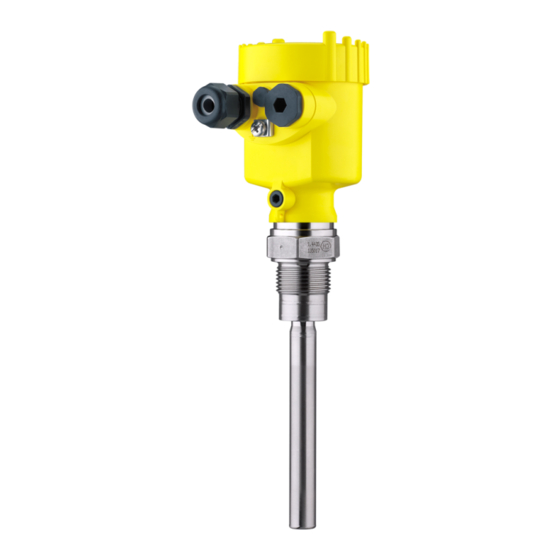
The VEGAVIB 61 consists of the components: Constituent parts Housing cover Housing with electronics Process fitting with vibrating rod Fig. 1: VEGAVIB 61 - with plastic housing Housing cover Housing with electronics Process fitting Type label The type label contains the most important data for identification and... -
Page 8: Principle Of Operation
3 Product description 3.2 Principle of operation VEGAVIB 61 is a point level sensor with vibrating rod for level Application area detection. It is designed for industrial use in all areas of process technology and is preferably used for bulk solids. -
Page 9: Storage And Transport
Not exposed to corrosive media Protected against solar radiation Avoiding mechanical shock and vibration Storage and transport Storage and transport temperature see chapter "Supplement - temperature Technical data - Ambient conditions" Relative humidity 20 … 85 % VEGAVIB 61 • - contactless electronic switch... -
Page 10: Mounting
You can find the specifications in chapter "Technical data" and on the type label. In general, VEGAVIB 61 can be installed in any position. The Switching point instrument only has to be mounted in such a way that the vibrating element is at the height of the desired switching point. -
Page 11: Instructions For Installation
"a"). In abrasive solids, mounting according to illustration "b" has proven. A spout forms in the concave protective sheet preventing wear of the protective sheet. VEGAVIB 61 • - contactless electronic switch... - Page 12 filling and emptying apertures into account. To compensate measurement errors caused by the material cone in cylindrical vessels, the sensor must be mounted at a distance of d/6 from the vessel wall. Fig. 4: Filling and emptying centred VEGAVIB 61 • - contactless electronic switch...
- Page 13 VEGAVIB 61 Discharge opening Filling opening To achieve a very precise switching point, you can install VEGAVIB 61 Horizontal installation horizontally. However, if the switching point can have a tolerance of a few centimeters, we recommend mounting VEGAVIB 61 approx. 20°...
- Page 14 If VEGAVIB 61 is mounted in the filling stream, unwanted false Inflowing medium measurement signals can be generated. For this reason, mount VEGAVIB 61 at a position in the vessel where no disturbances, e.g. from filling openings, agitators, etc., can occur. Baffle protection against...
- Page 15 4 Mounting VEGAVIB 61 • - contactless electronic switch...
-
Page 16: Connecting To Power Supply
Remove approx. 10 cm (4 in) of the cable mantle, strip approx. 1 cm (0.4 in) of insulation from the ends of the individual wires Insert the cable into the sensor through the cable entry VEGAVIB 61 • - contactless electronic switch... -
Page 17: Wiring Plan, Single Chamber Housing
10 If necessary, carry out a fresh adjustment 11 Screw the housing cover back on The electrical connection is finished. 5.3 Wiring plan, single chamber housing The following illustrations apply to the non-Ex as well as to the EEx-d version. VEGAVIB 61 • - contactless electronic switch... - Page 18 When VEGAVIB 61 is used as part of an overfill protection system according to WHG, also note the regulations of the general type approval.
- Page 19 5 Connecting to power supply Fig. 10: Wiring plan Shielding VEGAVIB 61 • - contactless electronic switch...
-
Page 20: Set Up
Note: As a rule, always set the mode with mode switch (2) before starting the setup of VEGAVIB 61. The switching output will change if you set the mode switch (2) afterwards. This could possibly trigger other connected instruments or devices. -
Page 21: Function Chart
6 Set up As a default setting, the potentiometer of VEGAVIB 61 is set to the complete right position (> 0.3 g/cm³/0.011 lbs/in³). In very light solids you have to turn the potentiometer to the complete left position (0.02 … 0.1 g/cm³ or 0.0007 … 0.0036 lbs/in³). By doing this, VEGAVIB 61 will be more sensitive and light solids can be detected more reliably. - Page 22 6 Set up Level Switching status Control lamp Mode min. Dry run protection Switch open Failure of the sup- ply voltage (min./max. mode) Switch open Malfunction Switch open flashes red VEGAVIB 61 • - contactless electronic switch...
-
Page 23: Maintenance And Fault Rectification
24 hour service hotline Should these measures not be successful, please call in urgent cases the VEGA service hotline under the phone no. +49 1805 858550. The hotline is available to you 7 days a week round-the-clock. Since we offer this service world-wide, the support is only available in the English language. -
Page 24: Exchanging The Electronics Module
Pull the connection cables out of the terminals Loosen the two screws with a screw driver (Torx size T10 or slot 4) Fig. 25: Loosening the holding screws Electronics module Screws (2 pcs.) VEGAVIB 61 • - contactless electronic switch... -
Page 25: Instrument Repair
If a repair is necessary, please proceed as follows: You can download a return form (23 KB) from our homepage at www. vega.com under: "Downloads - Forms and certificates - Repair form". By doing this you help us carry out the repair quickly and without having to call back for needed information. -
Page 26: Dismounting
Correct disposal avoids negative effects on humans and the environ- ment and ensures recycling of useful raw materials. Materials: see chapter "Technical data" If you have no way to dispose of the old instrument properly, please contact us concerning return and disposal. VEGAVIB 61 • - contactless electronic switch... -
Page 27: Supplement
0.5 s When immersed When laid bare Ambient conditions Ambient temperature on the housing -40 … +80 °C (-40 … +176 °F) Storage and transport temperature -40 … +80 °C (-40 … +176 °F) VEGAVIB 61 • - contactless electronic switch... - Page 28 Temperature range with temperature adapter Density > 0.05 g/cm³ (0.002 lbs/in³) Standard > 0.02 g/cm³ (0.0007 lbs/in³) adjustable Granular size no limitation max. 20 mm (0.8 in) with product density < 0.05 g/cm³ (0.002 lbs/in³). VEGAVIB 61 • - contactless electronic switch...
- Page 29 Instruments with approvals can have different technical data depending on the version. That's why the associated approval documents have to be noted with these instruments. They are part of the delivery or can be downloaded under www.vega.com via "VEGA Tools" and "serial number search" as well as via "Downloads" and "Approvals".
-
Page 30: Dimensions
(3.11") (3.03") M20x1,5 M20x1,5/ M20x1,5/ M20x1,5/ ½ NPT ½ NPT ½ NPT M20x1,5/ ½ NPT Fig. 28: Housing versions Plastic housing Stainless steel housing, electropolished Stainless steel housing - precision casting Aluminium housing VEGAVIB 61 • - contactless electronic switch... - Page 31 9 Supplement ø 29 mm (1.14") ø16 mm (0.63") Fig. 29: VEGAVIB 61, threaded version G1 A (DIN ISO 228/1) VEGAVIB 61 • - contactless electronic switch...
- Page 32 9 Supplement G1½A ø 29 mm (1.14") ø16mm (0.63") Fig. 30: VEGAVIB 61, threaded version G1½ A (DIN ISO 228/1) VEGAVIB 61 • - contactless electronic switch...
- Page 33 9 Supplement ø 34 mm ") Fig. 31: Temperature adapter VEGAVIB 61 • - contactless electronic switch...
-
Page 34: Information
Les lignes de produits VEGA sont globalement protégées par des droits de propriété intellectuelle. Pour plus d'informations, on pourra se référer au site http://www.vega. VEGA lineas de productos están protegidas por los derechos en el campo de la propiedad industrial. Para mayor información revise la pagina web http://www.vega.com Линии... - Page 35 9 Supplement VEGAVIB 61 • - contactless electronic switch...
-
Page 36: Information
All statements concerning scope of delivery, application, practical use and operating conditions of the sensors and processing systems correspond to the information avail- able at the time of printing. © VEGA Grieshaber KG, Schiltach/Germany 2012 29266-EN-120418 Subject to change without prior notice...
Need help?
Do you have a question about the VEGAVIB 61 and is the answer not in the manual?
Questions and answers