Vega VEGACAP 65 Operating Instructions Manual
Transistor npn/pnp, contactless electronic switch
Hide thumbs
Also See for VEGACAP 65:
- Operating instructions manual (44 pages) ,
- Operating instructions manual (44 pages) ,
- Operating instructions manual (36 pages)

Related Manuals for Vega VEGACAP 65


Summary of Contents for Vega VEGACAP 65
-
Page 1: Operating Instructions
Operating Instructions VEGACAP 65 - transistor (NPN/PNP) Document ID: 30018 Capacitive... -
Page 2: Table Of Contents
Disposal ....... . . 29 VEGACAP 65 • - transistor (NPN/PNP) -
Page 3: Vegacap 65 • - Transistor (Npn/Pnp)
Instructions manuals for accessories and replacement parts Tip: To ensure reliable setup and operation of your VEGACAP 65, we offer accessories and replacement parts. The associated documents are: 30174 - Electronics module VEGACAP series 60 34296 - Protective cover 31088 - Flanges according to DIN-EN-ASME-JIS-GOST VEGACAP 65 •... -
Page 4: About This Document
This symbol indicates special instructions for Ex applications. List The dot set in front indicates a list with no implied sequence. à Action This arrow indicates a single action. Sequence Numbers set in front indicate successive steps in a procedure. VEGACAP 65 • - transistor (NPN/PNP) -
Page 5: For Your Safety
During work on and with the device the required personal protective equipment must always be worn. 2.2 Appropriate use VEGACAP 65 is a sensor for level detection. You can find detailed information on the application range in chapter "Product description". -
Page 6: Safety Label On The Instrument
2.6 CE conformity This device fulfills the legal requirements of the applicable EC guidelines. By attaching the CE mark, VEGA provides a confirmation of successful testing. You can find the CE conformity declaration in the download area of www.vega.com. -
Page 7: Product Description
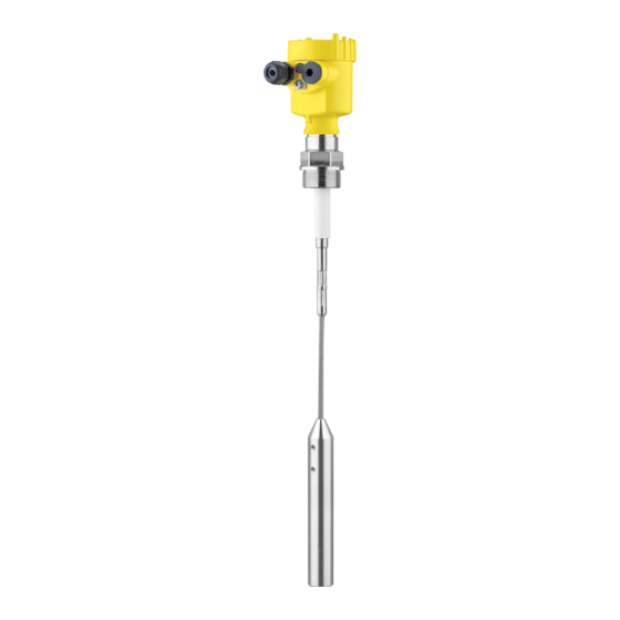
(NPN/PNP)" (optional) Supplementary instructions manual "Plug connector for level sensors" (optional) Ex-specific "Safety instructions" (with Ex-versions) if necessary, further certificates VEGACAP 65 consists of the following components: Components Housing cover Housing with electronics Process fitting with electrode VEGACAP 65 • - transistor (NPN/PNP) -
Page 8: Principle Of Operation
VEGACAP 65 is very rugged and maintenance-free and can be used in all areas of industrial process technology. Probes such as VEGACAP 65 can be used in solids and in non- conductive liquids. VEGACAP 65 • - transistor (NPN/PNP) -
Page 9: Operation
The capacitance change is converted by the electronics module into a switching command. VEGACAP 65 is a compact instrument, i.e. it can be operated without Power supply external evaluation system. The integrated electronics evaluates the level signal and outputs a switching signal. -
Page 10: Storage And Transport
Not exposed to corrosive media Protected against solar radiation Avoiding mechanical shock and vibration Storage and transport Storage and transport temperature see chapter "Supplement - temperature Technical data - Ambient conditions" Relative humidity 20 … 85 % VEGACAP 65 • - transistor (NPN/PNP) -
Page 11: Mounting
You can find the specifications in chapter "Technical data" or on the type label. In general, VEGACAP 65 must be mounted vertically. The instrument Switching point must be mounted in such a way that the probe is at the height of the requested switching point. -
Page 12: Mounting Instructions
For this reason, do not use an overly tion long probe for VEGACAP 65, but check if you can mount a short level switch on the side of the vessel in horizontal position. Inflowing medium If the instrument is mounted in the filling stream, unwanted false... - Page 13 filling and emptying apertures into account. To compensate measurement errors caused by the material cone in cylindrical vessels, the sensor must be mounted at a distance of d/6 from the vessel wall. Fig. 5: Filling and emptying centered VEGACAP 65 • - transistor (NPN/PNP)
- Page 14 Make sure that the max. permissible tensile load of the suspension cable is not exceeded. The danger of this happening exists particularly with very heavy solids and large meas. lengths. The max. permissible load is stated in chapter "Technical data". VEGACAP 65 • - transistor (NPN/PNP)
-
Page 15: Connect To Power Supply
Connect the operating voltage according to the following diagrams. Take note of the general installation regulations. As a rule, connect VEGACAP 65 to vessel ground (PA), or in case of plastic vessels, to the next ground potential. On the side of the instrument housing there is a ground terminal between the cable entries. -
Page 16: Wiring Plan, Single Chamber Housing
5.3 Wiring plan, single chamber housing Housing overview Fig. 8: Material versions, single chamber housing Plastic (not with dust-Ex) Aluminium Stainless steel Filter element for pressure compensation or blind stopper with version IP 66/ IP 68, 1 bar VEGACAP 65 • - transistor (NPN/PNP) - Page 17 DIL switch for mode adjustment Ground terminal Connection terminals Control lamp We recommend connecting VEGACAP 65 in such a way that the Wiring plan switching circuit is open when there is a level signal, line break or failure (safe condition).
- Page 18 5 Connect to power supply Fig. 10: Wiring plan Power supply Fig. 11: NPN action Fig. 12: PNP action VEGACAP 65 • - transistor (NPN/PNP)
-
Page 19: Wiring Plan - Version Ip 66/Ip 68, 1 Bar
Wire assignment, con- nection cable Fig. 13: Wire assignment connection cable. The numbers of the wires correspond to the terminals of the instrument. brown (+) voltage supply White Yellow blue (-) voltage supply Shielding VEGACAP 65 • - transistor (NPN/PNP) -
Page 20: Set Up
Note: As a rule, always set the mode with the mode switch (3) before starting setup VEGACAP 65. The switching output will change if you set the mode switch (3) afterwards. This could possibly trigger other connected instruments or devices. - Page 21 Screw the housing cover tightly up to the thread stop so that the inspection glass is above the control lamp (LED). To adjust VEGACAP 65, first of all remove the housing cover. Switching point adapta- You can adapt the switching point to the solid with the potentiometer.
-
Page 22: Functional Chart
Overflow protec- tion Mode min. transistor con- ducts Dry run protection Green Mode min. transistor blocks Dry run protection Failure of the sup- transistor blocks ply voltage (min./max. mode) Failure transistor blocks flashes red VEGACAP 65 • - transistor (NPN/PNP) -
Page 23: Maintenance And Fault Rectification
English language. The service is free of charge, only the standard telephone costs will be charged. VEGACAP 65 signals "covered" when the vibrating element is not Checking the switching signal submerged (overfill protection) - Page 24 à Exchange instrument or return instrument for repair Reaction after fault rec- Depending on the failure reason and measures taken, the steps tification described in chapter "Set up" must be carried out again, if necessary. VEGACAP 65 • - transistor (NPN/PNP)
-
Page 25: Exchange Of The Electronics Module
Otherwise the plug may be in a different position later. Insert the electronics module carefully. Make sure that the plug is in the correct position. 10 Screw in and tighten the two holding screws with a screwdriver (Torx size T10 or Phillips 4) VEGACAP 65 • - transistor (NPN/PNP) -
Page 26: Shortening Of The Probe
To avoid splicing of the steel cable, tin the cable before shortening with a soldering iron and tighten the wire. Shorten the cable with a cut-off wheel or metal saw at the lower end. Make sure the length is correct before shortening. VEGACAP 65 • - transistor (NPN/PNP) -
Page 27: Instrument Repair
(2) flashes green. Hence the probe is compensated to the modified length. Carry out the adjustment again. See chapter "Set-up, adjustment elements". 7.5 Instrument repair If a repair is necessary, please proceed as follows: VEGACAP 65 • - transistor (NPN/PNP) - Page 28 7 Maintenance and fault rectification You can download a return form (23 KB) from our Internet homepage www.vega.com under: "Downloads - Forms and certificates - Repair form". By doing this you help us carry out the repair quickly and without having to call back for needed information.
-
Page 29: Dismounting
Correct disposal avoids negative effects to persons and environment and ensures recycling of useful raw materials. Materials: see chapter "Technical data" If you have no possibility to dispose of the old instrument professionally, please contact us concerning return and disposal. VEGACAP 65 • - transistor (NPN/PNP) -
Page 30: Technical Data
Cable weight: ø 11 mm (0.433 in) 230 g/m (2.47 oz/ft) 0.4 … 32 m (1.312 … 105 ft) Sensor length (L) Cable connected electrically conductive with the gravity weight. Cable connected electrically conductive with the gravity weight. VEGACAP 65 • - transistor (NPN/PNP) - Page 31 -40 … +80 °C (-40 … +176 °F) Process conditions -1 … 64 bar/-100 … 6400 kPa (-14.5 … 928 psig) Process pressure Process temperature VEGACAP 65 of 316L Insulation PA -50 … +80 °C (-58 … +176 °F) Without insulation -50 …...
- Page 32 0.5 mm² Wire cross-section < 0.036 Ω/m (0.011 Ω/ft) Wire resistance Depending on the version M12 x 1, according to DIN 43650, Harting, 7/ 8" FF. VEGACAP 65 • - transistor (NPN/PNP)
- Page 33 PACTware for applications according to SIL. Functional safety according to IEC 61508-4 Single channel architecture (1oo1D) up to SIL2 double channel diversitary redundant up to SIL3 architecture (1oo2D) A suitable cable is the prerequisite for maintaining the protection rating. VEGACAP 65 • - transistor (NPN/PNP)
- Page 34 Depending on the version, instruments with approvals can have different technical data. For these instruments, the corresponding approval documents have to be taken into account. These are part of the delivery or can be downloaded under www.vega.com via "VEGA Tools" and "serial number search" as well as via "Downloads" and "Approvals".
-
Page 35: Dimensions
") ~ 150mm (5 ") ø 77mm ø 84mm (3 ") ") M20x1,5 M20x1,5 M20x1,5 Fig. 32: Housing versions in protection IP 66/IP 68, 1 bar Stainless steel housing - precision casting Aluminium housing VEGACAP 65 • - transistor (NPN/PNP) - Page 36 G 1 ½ A ø 6 mm ") ø 30 mm ") Fig. 33: VEGACAP 65 - cable version with ø 6 mm, threaded version G1 A (ISO 228 T1) = Sensor length, see chapter "Technical data" VEGACAP 65 • - transistor (NPN/PNP)
- Page 37 G 1 A ø 8 mm ") ø 30 mm ") Fig. 34: VEGACAP 65 - cable version with ø 8 mm, threaded version G1 A (ISO 228 T1) = Sensor length, see chapter "Technical data" VEGACAP 65 • - transistor (NPN/PNP)
- Page 38 G 1 A ø 11 mm ") ø 30 mm ") Fig. 35: VEGACAP 65 - cable version with ø 11 mm, threaded version G1 A (ISO 228 T1) = Sensor length, see chapter "Technical data" VEGACAP 65 • - transistor (NPN/PNP)
- Page 39 9 Supplement ø 40 mm (1.58") Fig. 36: Temperature adapter ø 16 mm (0.63") Fig. 37: VEGACAP 65 - screening tube - fro example against strong condensation VEGACAP 65 • - transistor (NPN/PNP)
-
Page 40: Information
Les lignes de produits VEGA sont globalement protégées par des droits de propriété intellectuelle. Pour plus d'informations, on pourra se référer au site http://www.vega.com VEGA lineas de productos están protegidas por los derechos en el campo de la propiedad industrial. Para mayor información revise la pagina web http://www.vega.com Линии... - Page 41 9 Supplement VEGACAP 65 • - transistor (NPN/PNP)
- Page 42 9 Supplement VEGACAP 65 • - transistor (NPN/PNP)
- Page 43 9 Supplement VEGACAP 65 • - transistor (NPN/PNP)
-
Page 44: Information
All statements concerning scope of delivery, application, practical use and operating conditions of the sensors and processing systems correspond to the information avail- able at the time of printing. © VEGA Grieshaber KG, Schiltach/Germany 2009 30018-EN-090604 Subject to change without prior notice...
Need help?
Do you have a question about the VEGACAP 65 and is the answer not in the manual?
Questions and answers