Vega VEGAWAVE 61 Operating Instructions Manual
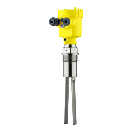
Vibrating level switch for powders
Hide thumbs
Also See for VEGAWAVE 61:
- Operating instructions manual (40 pages) ,
- Operating instructions manual (36 pages) ,
- Operating instructions manual (40 pages)

Subscribe to Our Youtube Channel
Related Manuals for Vega VEGAWAVE 61


Summary of Contents for Vega VEGAWAVE 61
- Page 1 Operating Instructions Vibrating level switch for powders VEGAWAVE 61 Two-wire 8/16 mA Document ID: 32250...
-
Page 2: Table Of Contents
Exchanging the electronics module ................27 How to proceed if a repair is necessary ................28 Dismount..........................30 Dismounting steps......................30 Disposal ......................... 30 Supplement ..........................31 Technical data ........................ 31 Dimensions ........................35 Industrial property rights ....................37 VEGAWAVE 61 • Two-wire 8/16 mA... - Page 3 Contents Trademark ........................37 Safety instructions for Ex areas: Take note of the Ex specific safety instructions for Ex applications. These instructions are attached as documents to each instrument with Ex approval and are part of the operating instructions. Editing status: 2022-09-15 VEGAWAVE 61 • Two-wire 8/16 mA...
-
Page 4: About This Document
Symbols used Document ID This symbol on the front page of this instruction refers to the Docu- ment ID. By entering the Document ID on www.vega.com you will reach the document download. Information, note, tip: This symbol indicates helpful additional infor- mation and tips for successful work. -
Page 5: For Your Safety
During work on and with the device, the required personal protective equipment must always be worn. Appropriate use The VEGAWAVE 61 is a sensor for point level detection. You can find detailed information about the area of application in chapter " Product description". Operational reliability is ensured only if the instrument is properly used according to the specifications in the operating instructions manual as well as possible supplementary instructions. -
Page 6: Safety Label On The Instrument
The corresponding conformity declarations can be found on our homepage. SIL conformity VEGAWAVE 61 meets the requirements to the functional safety ac- cording to IEC 61508. Further information is available in the Safety Manual " VEGAWAVE series 60". Installation and operation in the USA and Canada This information is only valid for USA and Canada. -
Page 7: Product Description
Principle of operation Application area VEGAWAVE 61 is a point level sensor with tuning fork for point level detection. VEGAWAVE 61 • Two-wire 8/16 mA... -
Page 8: Adjustment
Solid detection in water If VEGAWAVE 61 was ordered for solids detection in water, the tuning fork is set to the density of water. In air or when immersed in water (density: 1 g/cm³/0.036 lbs/in), VEGAWAVE 61 signals "uncovered". - Page 9 Technical data - Ambient conditions" • Relative moisture 20 … 85 % Lifting and carrying With instrument weights of more than 18 kg (39.68 lbs) suitable and approved equipment must be used for lifting and carrying. VEGAWAVE 61 • Two-wire 8/16 mA...
-
Page 10: Mounting
Switching point In general, VEGAWAVE 61 can be installed in any position. The instru- ment only has to be mounted in such a way that the vibrating element is at the height of the desired switching point. -
Page 11: Mounting Instructions
4 Mounting Fig. 2: Measures against moisture ingress Transport Do not hold VEGAWAVE 61 on the vibrating element. Especially with flange and tube versions, the sensor can be damaged by the weight of the instrument. Remove the protective cover just before mounting. Pressure/Vacuum The process fitting must be sealed if there is gauge or low pressure in the vessel. Before use, check if the sealing material is resistant against the measured product and the process temperature. - Page 12 Horizontal mounting To achieve a very precise switching point, you can install VEGAWAVE 61 horizontally. However, if the switching point can have a tolerance of a few centimeters, we recommend mounting VEGAWAVE 61 approx. 20° inclined to the vessel bottom to avoid buildup. VEGAWAVE 61 • Two-wire 8/16 mA...
- Page 13 Fig. 4: Horizontal mounting Inflowing medium If VEGAWAVE 61 is mounted in the filling stream, unwanted false measurement signals can be generated. For this reason, mount VEGAWAVE 61 at a position in the vessel where no disturbances, e.g. from filling openings, agitators, etc., can occur. Product flow To make sure the tuning fork of VEGAWAVE 61 generates as little resistance as possible to product flow, mount the sensor so that the surfaces are parallel to the product movement.
- Page 14 Marking on top with screwed version Baffle protection against In applications such as grit chambers or settling basins for coarse falling rocks sediments, the vibrating element must be protected against damage with a suitable baffle. This baffle must be manufactured by you. > 125 mm (> 5") Fig. 7: Baffle for protection against mechanical damage VEGAWAVE 61 • Two-wire 8/16 mA...
-
Page 15: Connecting To Power Supply
Voltage supply Connect the voltage supply according to the following diagrams. Take note of the general installation regulations. As a rule, connect VEGA- WAVE 61 to vessel ground (PA), or in case of plastic vessels, to the next ground potential. On the side of the instrument housing there is a ground terminal between the cable entries. -
Page 16: Wiring Plan, Single Chamber Housing
10. If necessary, carry out a fresh adjustment 11. Screw the housing lid back on The electrical connection is finished. Wiring plan, single chamber housing The following illustrations apply to the non-Ex as well as to the Ex-d version. VEGAWAVE 61 • Two-wire 8/16 mA... - Page 17 For further information see the " Technical data" in the " Supplement". The wiring example is applicable for all suitable controllers. If the mode switch of VEGAWAVE 61 is correctly set to "max.", the control lamp on VEGAWAVE 61 lights. •...
-
Page 18: Wiring Plan - Version Ip66/Ip68, 1 Bar
5 Connecting to power supply Wiring plan - version IP66/IP68, 1 bar Wire assignment, con- nection cable Fig. 11: Wire assignment, connection cable Brown (+) and blue (-) to power supply or to the processing system Shielding VEGAWAVE 61 • Two-wire 8/16 mA... -
Page 19: Setup
Note: As a rule, always set the mode with mode switch (2) before starting the setup of VEGAWAVE 61 . If the instrument is used in conjunction with a controller, always set the mode switch (2) on VEGAWAVE 61 to max. -
Page 20: Function Table
6 Setup By default, the potentiometer of VEGAWAVE 61 is set to the right stop (> 0.02 g/cm³ or 0.0008 lbs/in³). In case of very light-weight solids, turn the potentiometer to the left stop (> 0.008 g/cm³ or 0.0003 lbs/ in³). - Page 21 The following table provides an overview of the switching conditions depending on the adjusted mode of the controller and the level. Note: Keep in mind that the mode switch of VEGAWAVE 61 must be always set to "max.". Mode on the con-...
-
Page 22: Proof Test (Sil)
SPLC must be monitored. The sensor must neither be dismounted nor triggered by filling the vessel. You can carry out the function test with the output current values also directly via a safety PLC or a process control system. VEGAWAVE 61 • Two-wire 8/16 mA... - Page 23 Push the test key for > 2 seconds with a suitable object (screwdriver, pen, etc.). When the VEGAWAVE 61 is connected to a processing system or an SPLC, you have to interrupt the connection cable to the sensor for > 2 seconds.
- Page 24 2. Empty 8 mA energized currentless energized signal ±1.5 mA 1.5 s ±0.5 s 3. Full signal 16 mA currentless energized energized ±1.5 mA 1.5 s ±0.5 s 2) Starting time of the voltage supply VEGAWAVE 61 • Two-wire 8/16 mA...
- Page 25 Test assessment (SPLC) Test passed Status Current value Time False signal < 3.6 mA 1.5 s ±0.5 s Uncovered 8 mA ±1.5 mA 1.5 s ±0.5 s Covered 16 mA ±1.5 mA 1.5 s ±0.5 s VEGAWAVE 61 • Two-wire 8/16 mA...
-
Page 26: Maintenance And Fault Rectification
24 hour service hotline Should these measures not be successful, please call in urgent cases the VEGA service hotline under the phone no. +49 1805 858550. The hotline is manned 7 days a week round-the-clock. Since we offer this service worldwide, the support is only available in the English language. The service is free, only standard call charges are incurred. -
Page 27: Exchanging The Electronics Module
Check the vibrating element and the sensor for buildup ement and remove the buildup if there is any. Wrong mode selected Set the mode switch on VEGAWAVE 61 to "max". Set the correct mode on the controller (A: overfill protection; B: dry run protection). Signal lamp flashes red Error on the vibrating el-... -
Page 28: How To Proceed If A Repair Is Necessary
How to proceed if a repair is necessary You can find an instrument return form as well as detailed information about the procedure in the download area of our homepage. By doing this you help us carry out the repair quickly and without having to call back for needed information. VEGAWAVE 61 • Two-wire 8/16 mA... - Page 29 Clean the instrument and pack it damage-proof • Attach the completed form and, if need be, also a safety data sheet outside on the packaging • Ask the agency serving you to get the address for the return ship- ment. You can find the agency on our homepage. VEGAWAVE 61 • Two-wire 8/16 mA...
-
Page 30: Dismount
If personal data is stored on the old device to be disposed of, delete it before disposal. If you have no way to dispose of the old instrument properly, please contact us concerning return and disposal. VEGAWAVE 61 • Two-wire 8/16 mA... -
Page 31: Supplement
Ʋ Pipe thread, cylindrical (DIN 3852-A) G1½ Ʋ Pipe thread, conical (ASME B1.20.1) 1½ NPT Instrument weight (depending on pro- 0.8 … 4 kg (0.18 … 8.82 lbs) cess fitting) Max. lateral load 600 N (135 lbf) VEGAWAVE 61 • Two-wire 8/16 mA... - Page 32 -40 … +80 °C (-40 … +176 °F) Process conditions Measured variable Limit level of solids Process pressure -1 … 25 bar/-100 … 2500 kPa (-14.5 … 363 psig) VEGAWAVE 61 of 316L -50 … +150 °C (-58 … +302 °F) Process temperature (thread or flange -50 … +250 °C (-58 … +482 °F) temperature) with temperature adapter (option) VEGAWAVE 61 • Two-wire 8/16 mA...
- Page 33 Ʋ Wire resistance < 0.036 Ω/m (0.011 Ω/ft) Ʋ Tensile strength < 1200 N (270 lbf) Ʋ Standard length 5 m (16.4 ft) Ʋ Max. length 1000 m (3280 ft) Ʋ Min. bending radius 25 mm (0.984 in) with 25 °C (77 °F) VEGAWAVE 61 • Two-wire 8/16 mA...
- Page 34 For that reason the associated approval documents of these instruments have to be carefully noted. They are part of the delivery or can be downloaded by entering the serial number of your instrument into the search field under www.vega.com as well as in the general download area. VEGAWAVE 61 • Two-wire 8/16 mA...
-
Page 35: Dimensions
~ 103 mm (5.91") (4.06") ø 77 mm ø 84 mm (3.03") (3.31") M20x1,5 M20x1,5 M20x1,5 Fig. 18: Housing versions with protection rating IP66/IP68 (1 bar) Stainless steel single chamber (precision casting) Aluminium - single chamber VEGAWAVE 61 • Two-wire 8/16 mA... - Page 36 9 Supplement G1½ ø 43 mm (1.69") Fig. 19: VEGAWAVE 61, threaded version G1½ (DIN ISO 228/1) ø 34 mm (1.34") Fig. 20: Temperature adapter VEGAWAVE 61 • Two-wire 8/16 mA...
-
Page 37: Industrial Property Rights
Les lignes de produits VEGA sont globalement protégées par des droits de propriété intellec- tuelle. Pour plus d'informations, on pourra se référer au site www.vega.com. VEGA lineas de productos están protegidas por los derechos en el campo de la propiedad indus- trial. Para mayor información revise la pagina web www.vega.com. - Page 38 Notes VEGAWAVE 61 • Two-wire 8/16 mA...
- Page 39 Notes VEGAWAVE 61 • Two-wire 8/16 mA...
- Page 40 Subject to change without prior notice © VEGA Grieshaber KG, Schiltach/Germany 2022 VEGA Grieshaber KG Am Hohenstein 113 Phone +49 7836 50-0 77761 Schiltach E-mail: info.de@vega.com...
Need help?
Do you have a question about the VEGAWAVE 61 and is the answer not in the manual?
Questions and answers