Vega VEGASWING 63 Operating Instructions Manual
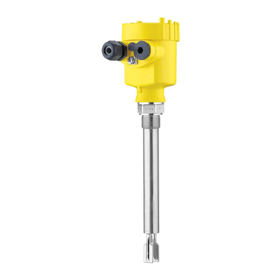
Vibrating level switch with tube extension for liquids
Hide thumbs
Also See for VEGASWING 63:
- Operating instructions manual (48 pages) ,
- Operating instructions manual (40 pages) ,
- Operating instructions manual (40 pages)

Related Manuals for Vega VEGASWING 63


Summary of Contents for Vega VEGASWING 63
- Page 1 Operating Instructions Vibrating level switch with tube extension for liquids VEGASWING 63 NAMUR Document ID: 29231...
-
Page 2: Table Of Contents
Exchanging the electronics .................... 25 How to proceed if a repair is necessary ................26 Dismount..........................27 Dismounting steps......................27 Disposal ......................... 27 Supplement ..........................28 Technical data ........................ 28 Dimensions ........................36 Industrial property rights ....................40 VEGASWING 63 • NAMUR... - Page 3 Contents Trademark ........................40 Safety instructions for Ex areas: Take note of the Ex specific safety instructions for Ex applications. These instructions are attached as documents to each instrument with Ex approval and are part of the operating instructions. Editing status: 2023-01-19 VEGASWING 63 • NAMUR...
-
Page 4: About This Document
Symbols used Document ID This symbol on the front page of this instruction refers to the Docu- ment ID. By entering the Document ID on www.vega.com you will reach the document download. Information, note, tip: This symbol indicates helpful additional infor- mation and tips for successful work. -
Page 5: For Your Safety
During work on and with the device, the required personal protective equipment must always be worn. Appropriate use The VEGASWING 63 is a sensor for point level detection. You can find detailed information about the area of application in chapter " Product description". Operational reliability is ensured only if the instrument is properly used according to the specifications in the operating instructions manual as well as possible supplementary instructions. -
Page 6: Sil Conformity
That is why we have introduced an environment management system with the goal of continuously improving company environmental pro- tection. The environment management system is certified according to DIN EN ISO 14001. Please help us fulfil this obligation by observing the environmental instructions in this manual: • Chapter " Packaging, transport and storage" • Chapter " Disposal" VEGASWING 63 • NAMUR... -
Page 7: Product Description
– If necessary, further certificates Information: Optional instrument features are also described in this operating instructions manual. The respective scope of delivery results from the order specification. Constituent parts The VEGASWING 63 consists of the components: • Housing lid • Housing with electronics •... -
Page 8: Principle Of Operation
Principle of operation VEGASWING 63 is a point level sensor with tuning fork for point level Application area detection. It is designed for industrial use in all areas of process technology and can be used in liquids. -
Page 9: Storage And Transport
With instrument weights of more than 18 kg (39.68 lbs) suitable and approved equipment must be used for lifting and carrying. Accessories The instructions for the listed accessories can be found in the down- load area on our homepage. VEGASWING 63 • NAMUR... - Page 10 For connecting the sensors with a separator to voltage supply or sig- nal processing, the sensors are also available with plug connectors. The following plug connectors are available: • M12 x 1 • ISO 4400 • Harting HAN 7D • Harting HAN 8D • Amphenol-Tuchel VEGASWING 63 • NAMUR...
-
Page 11: Mounting
Switching point In general, VEGASWING 63 can be installed in any position. The instrument only has to be mounted in such a way that the tuning fork is at the height of the desired switching point. - Page 12 Switching point approx. 27 mm (1.06 in) Fig. 3: Horizontal mounting Switching point Marking with screwed version, facing up Fig. 4: Horizontal installation (recommended mounting position, particularly for adhesive products) Switching point Marking with screwed version, facing up In the case of flange versions, the fork is aligned as follows. VEGASWING 63 • NAMUR...
- Page 13 To maintain the housing protection, make sure that the housing lid is closed during operation and locked, if necessary. Caution: Transport Do not hold VEGASWING 63 on the tuning fork. Particularly with flange or tube versions, the tuning fork can be damaged just by the weight of the instrument. Transport coated instruments very carefully and avoid touching the tuning fork.
-
Page 14: Mounting Instructions
Mounting instructions Welded socket VEGASWING 63 has a defined thread starting point. This means that every VEGASWING 63 is in the same fork position after being screwed in. Remove therefore the supplied seal from the thread of VEGASWING 63. This seal is not required when using a welded socket with O-ring in front. - Page 15 VEGASWING 63 at a position in the vessel where no disturbances, e.g. from filling openings, agitators, etc., can occur. This applies particularly to instrument types with long extension tube. Fig. 7: Inflowing medium Product flow To make sure the tuning fork of VEGASWING 63 generates as little resistance as possible to product flow, mount the sensor so that the surfaces are parallel to the product movement. Agitators Due to the effects of agitators, equipment vibration or similar, the level switch can be subjected to strong lateral forces.
- Page 16 See " Technical data". Caution: If it is determined (e.g. via a fault signal from VEGASWING 63) that medium has already penetrated into the vibrating element, the instru- ment must be exchanged immediately.
-
Page 17: Connecting To Power Supply
Connect the voltage supply according to the following diagrams. Take note of the general installation regulations. As a rule, connect VEGASWING 63 to vessel ground (PA), or in case of plastic vessels, to the next ground potential. On the side of the instrument housing there is a ground terminal between the cable entries. -
Page 18: Wiring Plan, Single Chamber Housing
Plastic (not with Ex d) Aluminium Stainless steel (not with Ex d) Stainless steel, electropolished (not with Ex d) Filter element for pressure compensation or blind plug with version IP66/ IP68, 1 bar (not with Ex d) VEGASWING 63 • NAMUR... - Page 19 Fig. 10: Electronics and connection compartment, single chamber housing Control lamp DIL switch for characteristics reversal DIL switch for sensitivity adjustment Ground terminal 5 EMC filter element Simulation key Connection terminals Wiring plan For connection of the amplifier according to NAMUR (IEC 60947-5-6, EN 50227). You can find further information in the " Technical data". Fig. 11: Wiring plan, single chamber housing VEGASWING 63 • NAMUR...
-
Page 20: Wiring Plan - Version Ip66/Ip68, 1 Bar
5 Connecting to power supply Wiring plan - version IP66/IP68, 1 bar Wire assignment, con- nection cable Fig. 12: Wire assignment, connection cable Brown (+) and blue (-) to power supply or to the processing system Shielding VEGASWING 63 • NAMUR... -
Page 21: Setup
DIL switch for adjustment of the density range (3) • Simulation key (4) Note: Always immerse the tuning fork of VEGASWING 63 in a liquid to test its function. Do not test the function of VEGASWING 63 with your hand. This can damage the sensor. Adjustment elements Fig. -
Page 22: Function Table
Function table The following table provides an overview of the switching conditions depending on the set mode and the level. Note: The mode setting on the NAMUR amplifier must be selected in such a way that the switching output takes on safe state in case of fault signal (I ≤ 0.6 mA). VEGASWING 63 • NAMUR... - Page 23 6 Setup Level Switching status Control lamp Falling character- ≥ 2.2 mA istics max. Falling character- ≤ 1.0 mA istics max. Rising character- ≥ 2.2 mA istics min. Rising character- ≤ 1.0 mA istics min. Fault ≤ 1.0 mA flashes red VEGASWING 63 • NAMUR...
-
Page 24: Maintenance And Fault Rectification
24 hour service hotline Should these measures not be successful, please call in urgent cases the VEGA service hotline under the phone no. +49 1805 858550. The hotline is also available outside normal working hours, seven days a week around the clock. -
Page 25: Exchanging The Electronics
In general, all electronics modules of series SW60 can be inter- changed. If you want to use an electronics module with a different signal output, you carry out the complete setup. You find the neces- sary, suitable operating instruction on our homepage. Note: Keep in mind that enamelled instrument versions need special electronics modules. These electronics modules are called SW60E or SW60E1. VEGASWING 63 • NAMUR... -
Page 26: How To Proceed If A Repair Is Necessary
Clean the instrument and pack it damage-proof • Attach the completed form and, if need be, also a safety data sheet outside on the packaging • Ask the agency serving you to get the address for the return ship- ment. You can find the agency on our homepage. VEGASWING 63 • NAMUR... -
Page 27: Dismount
If personal data is stored on the old device to be disposed of, delete it before disposal. If you have no way to dispose of the old instrument properly, please contact us concerning return and disposal. VEGASWING 63 • NAMUR... -
Page 28: Supplement
Ʋ The Second Line of Defense (SLOD) is a second level of the process separation in the form of a gas-tight feedthrough in the lower part of the housing, preventing product from penetrating into the housing. VEGASWING 63 • NAMUR... - Page 29 Torque for NPT cable glands and Conduit tubes Ʋ Plastic housing max. 10 Nm (7.376 lbf ft) Ʋ Aluminium/Stainless steel housing max. 50 Nm (36.88 lbf ft) Gas-tight leadthrough (optional) Ʋ Leakage rate < 10 mbar l/s Ʋ Pressure resistance PN 64 VEGASWING 63 • NAMUR...
- Page 30 +18 … +30 °C (+64 … +86 °F) Ʋ Product density 1 g/cm³ (0.036 lbs/in³) (water) Ʋ Product viscosity 1 mPa s Ʋ Superimposed pressure 0 kPa Ʋ Sensor installation Vertically from top Ʋ Density selection switch ≥ 0.7 g/cm³ Measurement accuracy Deviation ± 1 mm (0.04 in) VEGASWING 63 • NAMUR...
- Page 31 ") ") (0,022) (0,029) (0,036) (0,043) (0,051) (0,058) (0,065) (0,072) (0,079) (0,087) Fig. 15: Influence of the product density on the switching point Shifting of the switching point in mm (in) Product density in g/cm³ (lb/in³) Switch position ≥ 0.5 g/cm³ (0.018 lb/in³) Switch position ≥ 0.7 g/cm³ (0.025 lb/in³) Switching point at reference conditions (notch) Tuning fork VEGASWING 63 • NAMUR...
- Page 32 100 bar/10000 kPa (1450 psig) or 1.5 times process pressure The function of the instrument is ensured up to an operating pressure of 100 bar/10000 kPa (1450 psig) at a maximum process temperature of +50 °C (+122 °F) (only with threaded versions). VEGASWING 63 • NAMUR...
- Page 33 Ʋ VEGASWING 63 enamelled -50 … +200 °C (-58 … +392 °F) Ʋ VEGASWING 63 with ECTFE coating -50 … +150 °C (-58 … +302 °F) Ʋ VEGASWING 63 with PFA coating -50 … +250 °C (-58 … +482 °F) Ʋ...
- Page 34 Ʋ Closing cap ½ NPT Screw terminals for wire cross-section up to 1.5 mm² (AWG 16) Electromechanical data - version IP66/IP68 (1 bar) Options of the cable entry Ʋ Cable entry M20 x 1.5; ½ NPT VEGASWING 63 • NAMUR...
- Page 35 IP66/IP68 (1 bar) acc. to IEC 60529, type 6P acc. to (optionally available) NEMA Altitude above sea level up to 5000 m (16404 ft) Overvoltage category Pollution degree A suitable cable is required for maintaining the protection rating. VEGASWING 63 • NAMUR...
-
Page 36: Dimensions
For that reason the associated approval documents of these instruments have to be carefully noted. They are part of the delivery or can be downloaded by entering the serial number of your instrument into the search field under www.vega.com as well as in the general download area. Dimensions Housing in protection IP66/IP67 and IP66/IP68 (0.2 bar) - Page 37 ~ 103 mm (5.91") (4.06") ø 77 mm ø 84 mm (3.03") (3.31") M20x1,5 M20x1,5 M20x1,5 Fig. 21: Housing versions with protection rating IP66/IP68 (1 bar) Stainless steel single chamber (precision casting) Aluminium - single chamber VEGASWING 63 • NAMUR...
- Page 38 "NPT) 41 (G1A, 1"NPT) "NPT G1A, 1"NPT ø 21,3 mm (0.84") ø 33,7 mm (1.33") Fig. 22: VEGASWING 63 Thread Clamp Cone DN 25 Slotted nut DN 40 Flange Tuchenhagen Varivent Sensor length, see chapter " Technical data" VEGASWING 63 • NAMUR...
- Page 39 9 Supplement VEGASWING 63, options Fig. 23: Options Gas-tight leadthrough Temperature adapter VEGASWING 63 • NAMUR...
-
Page 40: Industrial Property Rights
Les lignes de produits VEGA sont globalement protégées par des droits de propriété intellec- tuelle. Pour plus d'informations, on pourra se référer au site www.vega.com. VEGA lineas de productos están protegidas por los derechos en el campo de la propiedad indus- trial. Para mayor información revise la pagina web www.vega.com. - Page 41 Notes VEGASWING 63 • NAMUR...
- Page 42 Notes VEGASWING 63 • NAMUR...
- Page 43 Notes VEGASWING 63 • NAMUR...
- Page 44 Subject to change without prior notice © VEGA Grieshaber KG, Schiltach/Germany 2023 VEGA Grieshaber KG Am Hohenstein 113 Phone +49 7836 50-0 77761 Schiltach E-mail: info.de@vega.com...
Need help?
Do you have a question about the VEGASWING 63 and is the answer not in the manual?
Questions and answers