Vega VEGAWAVE 63 Operating Instructions Manual
Level switch transistor npn/pnp
Hide thumbs
Also See for VEGAWAVE 63:
- Operating instructions manual (40 pages) ,
- Operating instructions manual (36 pages) ,
- Operating instructions manual (36 pages)

Related Manuals for Vega VEGAWAVE 63


Summary of Contents for Vega VEGAWAVE 63
-
Page 1: Operating Instructions
Operating Instructions VEGAWAVE 63 - transistor (NPN/PNP) Document ID: 32258 Vibration... -
Page 2: Table Of Contents
Disposal ....... . . 26 VEGAWAVE 63 • - transistor (NPN/PNP) -
Page 3: Vegawave 63 • - Transistor (Npn/Pnp)
You can find them listed in chapter "Product description". Instructions manuals for accessories and replacement parts Tip: To ensure reliable setup and operation of your VEGAWAVE 63, we offer accessories and replacement parts. The corresponding doc- umentations are: 32357 - External housing - VEGAWAVE... -
Page 4: About This Document
This symbol indicates special instructions for Ex applications. List The dot set in front indicates a list with no implied sequence. à Action This arrow indicates a single action. Sequence Numbers set in front indicate successive steps in a procedure. VEGAWAVE 63 • - transistor (NPN/PNP) -
Page 5: For Your Safety
During work on and with the device the required personal protective equipment must always be worn. 2.2 Appropriate use The VEGAWAVE 63 is a sensor for level detection. You can find detailed information on the application range in chapter "Product description". -
Page 6: Safety Label On The Instrument
2.6 CE conformity This device fulfills the legal requirements of the applicable EC guidelines. By attaching the CE mark, VEGA provides a confirmation of successful testing. You can find the CE conformity declaration in the download area of "www.vega.com". -
Page 7: Product Description
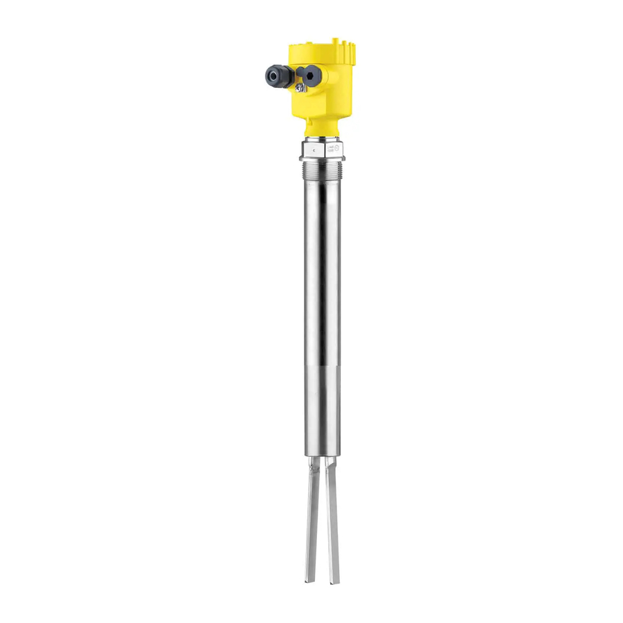
The VEGAWAVE 63 consists of the components: Constituent parts Housing cover Housing with electronics Process fitting with tuning fork Fig. 1: VEGAWAVE 63 - with plastic housing Housing cover Housing with electronics Process fitting Type label The type label contains the most important data for identification and... -
Page 8: Principle Of Operation
In addition to the type label outside, you can also find the serial number on the inside of the instrument. 3.2 Principle of operation VEGAWAVE 63 is a point level sensor with tuning fork for level Application area detection. -
Page 9: Operation
Not exposed to corrosive media Protected against solar radiation Avoiding mechanical shock and vibration Storage and transport Storage and transport temperature see chapter "Supplement - temperature Technical data - Ambient conditions" Relative humidity 20 … 85 % VEGAWAVE 63 • - transistor (NPN/PNP) -
Page 10: Mounting
You can find the specifications in chapter "Technical data" and on the type label. In general, VEGAWAVE 63 can be installed in any position. The Switching point instrument only has to be mounted in such a way that the vibrating element is at the height of the desired switching point. -
Page 11: Instructions For Installation
For this reason, do not tion use an overly long extension tube for VEGAWAVE 63, but check if you can mount a short level switch on the side of the vessel in horizontal position. - Page 12 4 Mounting Fig. 3: Inflowing medium VEGAWAVE 63 can be mounted with a lock fitting for height Lock fitting adjustment. Take note of the pressure information of the lock fitting. Socket The vibrating element should protrude into the vessel to avoid buildup.
- Page 13 4 Mounting Fig. 4: Filling and emptying centred Fig. 5: Filling in the centre, emptying laterally VEGAWAVE 63 Discharge opening Filling opening VEGAWAVE 63 • - transistor (NPN/PNP)
- Page 14 Baffle protection against In applications such as grit chambers or settling basins for coarse falling rocks sediments, the vibrating element must be protected against damage with a suitable baffle. This baffle must be manufactured by you. VEGAWAVE 63 • - transistor (NPN/PNP)
- Page 15 4 Mounting > 125 mm (> 5") Fig. 7: Baffle for protection against mechanical damage VEGAWAVE 63 • - transistor (NPN/PNP)
-
Page 16: Connecting To Power Supply
Voltage supply Take note of the general installation regulations. As a rule, connect VEGAWAVE 63 to vessel ground (PA), or in case of plastic vessels, to the next ground potential. On the side of the instrument housing there is a ground terminal between the cable entries. This connection serves to drain off... -
Page 17: Wiring Plan, Single Chamber Housing
10 If necessary, carry out a fresh adjustment 11 Screw the housing cover back on The electrical connection is finished. 5.3 Wiring plan, single chamber housing The following illustrations apply to the non-Ex as well as to the EEx-d version. VEGAWAVE 63 • - transistor (NPN/PNP) - Page 18 Filter element for pressure compensation or blind stopper with version IP 66/ IP 68, 1 bar (not with EEx d) We recommend connecting VEGAWAVE 63 in such a way that the Wiring plan switching circuit is open when there is a level signal, line break or failure (safe condition).
-
Page 19: Wiring Plan - Version Ip 66/Ip 68 (1 Bar)
Wire assignment con- nection cable Fig. 13: Wire assignment connection cable. The numbers of the wires correspond to the terminals of the instrument. brown (+) voltage supply White Yellow blue (-) voltage supply Shielding VEGAWAVE 63 • - transistor (NPN/PNP) -
Page 20: Set Up
Note: As a rule, always set the mode with mode switch (2) before starting the setup of VEGAWAVE 63. The switching output will change if you set the mode switch (2) afterwards. This could possibly trigger other connected instruments or devices. -
Page 21: Function Chart
6 Set up By default, the potentiometer of VEGAWAVE 63 is set to the right stop (> 0.02 g/cm³ or 0.0008 lbs/in³). In case of very light-weight solids, turn the potentiometer to the left stop (> 0.008 g/cm³ or 0.0003 lbs/in³). - Page 22 6 Set up Level Switching status Control lamp Failure of the sup- open ply voltage (min./max. mode) Malfunction open flashes red VEGAWAVE 63 • - transistor (NPN/PNP)
-
Page 23: Maintenance And Fault Rectification
24 hour service hotline Should these measures not be successful, please call in urgent cases the VEGA service hotline under the phone no. +49 1805 858550. The hotline is available to you 7 days a week round-the-clock. Since we offer this service world-wide, the support is only available in the English language. -
Page 24: Exchanging The Electronics Module
Lift the opening levers of the terminals with a screwdriver Pull the connection cables out of the terminals Loosen the two screws with a screw driver (Torx size T10 or slot 4) Fig. 25: Loosening the holding screws Electronics module Screws (2 pcs.) VEGAWAVE 63 • - transistor (NPN/PNP) -
Page 25: Instrument Repair
If a repair is necessary, please proceed as follows: You can download a return form (23 KB) from our homepage at www. vega.com under: "Downloads - Forms and certificates - Repair form". By doing this you help us carry out the repair quickly and without having to call back for needed information. -
Page 26: Dismounting
Correct disposal avoids negative effects on humans and the environ- ment and ensures recycling of useful raw materials. Materials: see chapter "Technical data" If you have no way to dispose of the old instrument properly, please contact us concerning return and disposal. VEGAWAVE 63 • - transistor (NPN/PNP) -
Page 27: Technical Data
Instrument weight (depending on proc- ess fitting) 2000 g/m (21.5 oz/ft) Extension tube 0.3 … 6 m (0.984 … 19.69 ft) Sensor length (L) 290 Nm, max. 600 N (214 lbf ft, max. 135 lbf) Max. lateral load VEGAWAVE 63 • - transistor (NPN/PNP) - Page 28 -1 … 25 bar/-100 … 2500 kPa (-14.5 … 363 psig) Process pressure VEGAWAVE 63 of 316L -50 … +150 °C (-58 … +302 °F) Process temperature (thread or flange tem- -50 … +250 °C (-58 … +482 °F) perature) with temperature adapter (option) VEGAWAVE 63 • - transistor (NPN/PNP)
- Page 29 1 x closing cap ½ NPT, 1 x blind plug ½ NPT Connection cable 0.5 mm² (AWG 20) Wire cross-section < 0.036 Ω/m (0.011 Ω/ft) Wire resistance Depending on the version M12 x 1, according to ISO 4400, Harting, 7/8" FF. VEGAWAVE 63 • - transistor (NPN/PNP)
- Page 30 Instruments with approvals can have different technical data depending on the version. That's why the associated approval documents have to be noted with these instruments. They are part of the delivery or can be downloaded under www.vega.com via "VEGA Tools" and "serial number search" as well as via "Downloads" and "Approvals".
-
Page 31: Dimensions
~ 150 mm (5.91") ø 77 mm ø 84 mm (3.31") (3.03") M20x1,5 M20x1,5 M20x1,5 Fig. 29: Housing versions with protection rating IP 66/IP 68 (1 bar) Stainless steel housing - precision casting Aluminium housing VEGAWAVE 63 • - transistor (NPN/PNP) - Page 32 9 Supplement G1½A ø 43mm (1 ") Fig. 30: VEGAWAVE 63, threaded version G1½ A (DIN ISO 228/1) Sensor length, see chapter "Technical data" VEGAWAVE 63 • - transistor (NPN/PNP)
- Page 33 9 Supplement ø 34 mm ") Fig. 31: Temperature adapter VEGAWAVE 63 • - transistor (NPN/PNP)
-
Page 34: Information
Les lignes de produits VEGA sont globalement protégées par des droits de propriété intellectuelle. Pour plus d'informations, on pourra se référer au site http://www.vega. VEGA lineas de productos están protegidas por los derechos en el campo de la propiedad industrial. Para mayor información revise la pagina web http://www.vega.com Линии... - Page 35 9 Supplement VEGAWAVE 63 • - transistor (NPN/PNP)
-
Page 36: Information
All statements concerning scope of delivery, application, practical use and operating conditions of the sensors and processing systems correspond to the information avail- able at the time of printing. © VEGA Grieshaber KG, Schiltach/Germany 2012 32258-EN-120418 Subject to change without prior notice...
Need help?
Do you have a question about the VEGAWAVE 63 and is the answer not in the manual?
Questions and answers