Vega VEGAKON 66 Operating Instructions Manual
Conductive limit switch for conductive liquids with relay output
Hide thumbs
Also See for VEGAKON 66:
- Operating instructions manual (28 pages) ,
- Operating instructions manual (20 pages)
Table of Contents
Advertisement
Quick Links
Advertisement
Table of Contents

Related Manuals for Vega VEGAKON 66


Summary of Contents for Vega VEGAKON 66
-
Page 1: Operating Instructions
Operating Instructions VEGAKON 66 with relay output Conductive... -
Page 2: Table Of Contents
Dismounting steps ..... . Disposal ......VEGAKON 66 - with relay output... - Page 3 Industrial property rights....Trademark ......VEGAKON 66 - with relay output...
-
Page 4: About This Document
This symbol indicates special instructions for Ex applications. List The dot set in front indicates a list with no implied sequence. à Action This arrow indicates a single action. Sequence Numbers set in front indicate successive steps in a procedure. VEGAKON 66 - with relay output... -
Page 5: For Your Safety
2.5 CE conformity VEGAKON 66 is in CE conformity with EMC (89/336/EWG) and LVD (73/23/EWG). Conformity has been judged according to the following standards:... -
Page 6: Environmental Instructions
The environment man- agement system is certified according to DIN EN ISO 14001. Please help us fulfil this obligation by observing the environ- mental instructions in this manual: Chapter "Packaging, transport and storage" Chapter "Disposal" VEGAKON 66 - with relay output... -
Page 7: Product Description
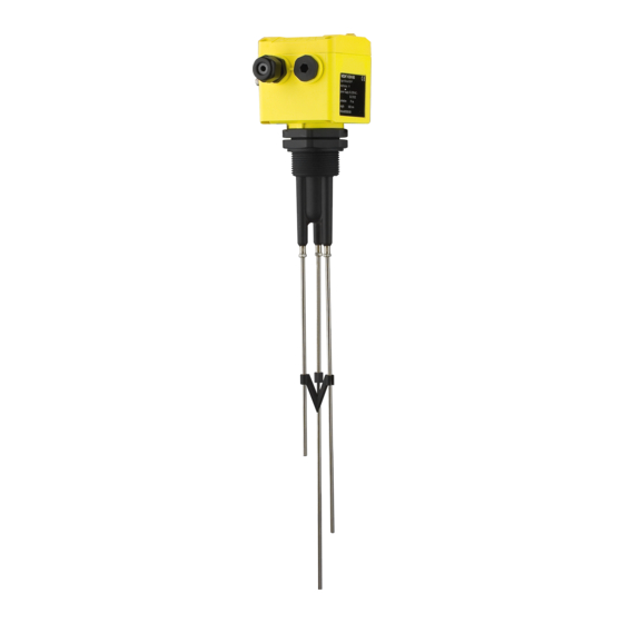
The scope of delivery encompasses: Scope of delivery VEGAKON 66 compact level switch Documentation - this operating instructions manual VEGAKON 66 consists of the following components: Components Housing cover Housing with electronics Process fitting with electrodes Fig. 1: VEGAKON 66... -
Page 8: Principle Of Operation
A level detection can be realised with two measuring electro- des, e.g. a pump or two-point control with three measuring electrodes. VEGAKON 66 is a compact instrument, i.e. it can be operated Supply without external evaluation system. The integrated electronics evaluates the level signal and outputs a switching signal. -
Page 9: Operation
Product description 3.3 Operation The VEGAKON 66 is a compact level switch with integrated oscillator. On the electronics module you will find the following indicating and adjustment elements: Control lamp for indication of the switching condition Mode changeover for selection of the output signal... -
Page 10: Mounting
Use the recommended cables (see chapter "Connecting to Moisture power supply") and tighten the cable gland. You can give your VEGAKON 66 additional protection against moisture penetration by leading the connection cable down- ward in front of the cable entry. Rain and condensation water can thus drain off. - Page 11 Mounting Fig. 4: Fasten the probe Probe Plastic socket on the probe end Probe Plastic socket laterally mounted VEGAKON 66 - with relay output...
-
Page 12: Connecting To Power Supply
Take note of the general installation regulations. As a rule, connect VEGAKON 66 to vessel ground (PA), or in case of plastic vessels, to the next ground potential. On the side of the housing there is a ground terminal between the cable entries. - Page 13 Connecting to power supply L1 N Fig. 5: Electronics with relay output Relay output Power supply VEGAKON 66 - with relay output...
-
Page 14: Set Up
The switching condition of the signal lamp can be checked Signal lamp (2) when the housing is closed. To adjust VEGAKON 66 loosen the four screws with a wrench on the upper side of the instrument and remove the housing cover. -
Page 15: Switching Point Adjustment
0.3 kΩ >1.7 mS 1 kΩ >540 µS 3 kΩ >180 µS 10 kΩ >54 µS 30 kΩ >20 µS 100 kΩ >5.7 µS 300 kΩ (sensitive) >1.6 µS Test min. Empty state is simulated VEGAKON 66 - with relay output... - Page 16 - cnductivity setting (3) generally to switch position 3 kΩ. Hence the instrument is already completely adjusted. Take note of the instructions in chart "Examples of conductivity values". The recommended settings take also influences such as e.g. condensation or slight buildup into account. VEGAKON 66 - with relay output...
- Page 17 2 Switch on voltage supply 3 Set the A/B switch to mode A 4 Set the rotary switch to position "TEST min." 5 Turn the rotary switch slowly clockwise until the red LED lights VEGAKON 66 - with relay output...
-
Page 18: Function Chart
When exchanging the electronics module, it is sufficient to take over the setting of the old electronics module. 6.4 Function chart The following chart provides an overview of the switching conditions depending on the adjusted mode and level. VEGAKON 66 - with relay output... - Page 19 Min. detection - Vessel full Min. detection - Vessel empty Note: If VEGAKON 66 is used for oil warning in water, the probe must be cleaned after having responded to oil (= empty signal) because otherwise resetting to water will not be ensured reliably.
-
Page 20: Maintenance And Fault Rectification
Maintenance and fault rectification 7 Maintenance and fault rectification 7.1 Maintenance When used as directed in normal operation, VEGAKON 66 is completely maintenance free. 7.2 Electronics exchange In general, all oscillators of series KONE66 can be inter- changed. If you want to use an oscillator with a different signal output, you can download the corresponding operating instructions manual from our homepage under Downloads. -
Page 21: Simulation Of Switching Functions
Maintenance and fault rectification As soon as you insert the electronics module, VEGAKON 66 is ready for operation. 7.3 Simulation of switching functions With the rotary switch for conductivity adjustment, full covering or empty signal can be simulated. The filling height must not be changed. You can hence easily check the response of connected signalling and switching facilities. -
Page 22: Dismounting
Correct disposal avoids negative effects to persons and environment and ensures recycling of useful raw materials. Materials: see chapter "Technical data" If you cannot dispose of the instrument properly, please contact us about disposal methods or return. VEGAKON 66 - with relay output... -
Page 23: Supplement
Relay output (DPDT), 2 floating spdts Output Turn-on voltage 10 mV - Min. 253 V AC, 253 V DC - Max. Switching current 10 µA - Min. 5 A AC, 1 A DC - Max. VEGAKON 66 - with relay output... - Page 24 20 … 253 V AC, 50/60 Hz, 20 … 72 V DC (at Supply voltage U >60 V DC, the ambient temperature can be max. 50 °C/122 °F) 1 … 9 VA (AC), approx. 1.5 W (DC) Power consumption VEGAKON 66 - with relay output...
- Page 25 Supplement Electrical protective measures Protection IP 66 - Plastic housing IP 66/IP 67 - Aluminium housing Overvoltage category Protection class VEGAKON 66 - with relay output...
-
Page 26: Dimensions
Supplement 9.2 Dimensions ~75mm ") 85mm ") M20x1,5 SW 60mm ") G1½A ø 4mm ") Fig. 21: VEGAKON 66 with three probes L1 Length ground probe L2 Length max. probe L3 Length min. probe VEGAKON 66 - with relay output... -
Page 27: Industrial Property Rights
Les lignes de produits VEGA sont globalement protégées par des droits de propriété intellectuelle. Pour plus d'informations, on pourra se référer au site http://www.vega.com. VEGA lineas de productos están protegidas por los derechos en el campo de la propiedad industrial. Para mayor información revise la pagina web http://www.vega.com. - Page 28 All statements concerning scope of delivery, application, practical use and operating conditions of the sensors and processing systems correspond to the information avail- able at the time of printing. © VEGA Grieshaber KG, Schiltach/Germany 2007 32649-EN-070615 Subject to change without prior notice...
Need help?
Do you have a question about the VEGAKON 66 and is the answer not in the manual?
Questions and answers