Vega VEGASWING 61 Operating Instructions Manual
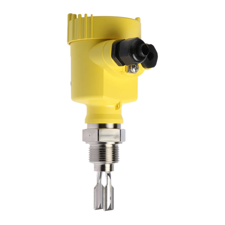
Vibrating level switches used for level detection of liquids
Hide thumbs
Also See for VEGASWING 61:
- Operating instructions manual (44 pages) ,
- Operating instructions manual (40 pages) ,
- Operating instructions manual (40 pages)
Table of Contents
Advertisement
Advertisement
Table of Contents

Related Manuals for Vega VEGASWING 61


Summary of Contents for Vega VEGASWING 61
-
Page 1: Operating Instructions
Operating Instructions VEGASWING 61, 63 with oscillator SW E60N (EX) -
Page 2: Table Of Contents
3.2 Technical data ............... 6 3.3 Dimensions ................. 10 Mounting ................... 12 4.1 VEGASWING ..............12 Electrical connection .............. 16 5.1 VEGASWING 61 and 63 ............ 16 Set-up ..................17 6.1 VEGASWING 61 and 63 ............ 17 6.2 Function chart ..............19 Safety information... -
Page 3: Product Description
• Insensitive to external vibration. protection. Using a tuning fork with a length • Process pressure up to 64 bar. of only 40 mm, VEGASWING 61 opens up • Also ECTFE or PFA coated or enamelled. new areas of application, e.g. in pipelines •... -
Page 4: Function And Application
Measuring system with VEGASWING as NAMUR compact instrument A measuring system consists of: - a VEGASWING vibrating level switch with integrated oscillator SW E60N - a NAMUR amplifier acc. to IEC 60947-5-6 (EN 50 227 / DIN 19 234). VEGASWING 61, 63 - N... -
Page 5: Types And Versions
• • • • Oscillator Two-wire output (SW E60N) NAMUR acc. to IEC 60947-5-6 • • • • Adapters Temperature adapter 1.4435 (316 L) up to 250°C • • • • Gastight leadthrough • • VEGASWING 61, 63 - N... -
Page 6: Technical Data
80 mm … 6000 mm - Hastelloy C4 enamelled 80 mm … 1500 mm - 1.4435 (316 L) ECTFE coated 80 mm … 3000 mm - 1.4435 (316 L) PFA coated 80 mm … 3000 mm VEGASWING 61, 63 - N... - Page 7 Temperature shock without limitation Permissible ambient temperature With temperature adapter 70˚C 40˚C 0˚C Process tempera- -50˚C ture 0˚C 50˚C 100˚C 150˚C 200˚C 250˚C -40˚C Process pressure Process pressure max. 64 bar depending on the mechanical connection VEGASWING 61, 63 - N...
- Page 8 ≤ 1.0 mA = Low current red flashing ≤ 1.0 mA = failure CE conformity VEGASWING 61 and 63 vibrating level switches meet the protective regulations of EMC (89/336/EWG) and NSR (73/23/EWG). Conformity has been judged acc. to the following standards:...
- Page 9 Ambient temperature on the housing -40°C … 70°C Process temperature -50°C … 150°C - test report VEGASWING 61 EX and 63 EX with oscillator SW E60N EX and suitable signal conditioning instrument - with temperature adapter up to 250°C Process pressure max.
-
Page 10: Dimensions
Thread G¾A or ¾ NPT Flange DN 25 PN 40 Tri-Clamp 1½" Conus DN 25 Bolting DN 40 SW32 21,3 Switching point * with display Also in version with switching point extension to VEGASWING 81A. VEGASWING 61, 63 - N... - Page 11 L = 180 mm Thread Conus G¾A or ¾ NPT Flange DN 25 PN 40 Tri-Clamp 1½" Bolting DN 40 DN 25 SW32 ø 21,3 Switching point * with display VEGASWING 61, 63 - N...
-
Page 12: Mounting
Direct exchange of a VEGASWING 81A Fig. 2.2 or 71A (with thread G1A) If VEGASWING 61 with a sensor length the same as VEGASWING 81A or 71A is mounted into an existing mounting boss G1A, it is ensured that VEGASWING 61 will seal correctly. - Page 13 (see fig. 2.2). The orientation of the tuning fork is marked by a notch on the hexagon of VEGA- SWING. With this you can check the orienta- tion of the tuning fork when screwing it in.
- Page 14 (see fig. 2.5). The sur- should be installed such that the surfaces of faces of the tuning fork should be parallel to the tuning fork are aligned with that direction. the product movement. VEGASWING 61, 63 - N...
- Page 15 The welded socket has a marking (notch). Weld the socket with the notch facing up- wards, or in the case of pipelines, aligned with the direction of flow (see fig. 2.6). Marking Fig. 2.6 VEGASWING 61, 63 - N...
-
Page 16: Electrical Connection
Electrical connection 5 Electrical connection 5.1 VEGASWING 61 and 63 Two-wire NAMUR output (SW E60N) For connection to isolation amplifiers acc. to Note NAMUR (IEC 60947-5-6, EN 50227) Switch off the power supply before starting (for further information see 3.2 Technical connection work. -
Page 17: Set-Up
Set-up 6 Set-up 6.1 VEGASWING 61 and 63 Switching point adaptation (3) The numbers in brackets relate to the follow- With this DIL switch (3) you can set the ing illustration. switching point for liquids with a density between 0.5 and 0.7 g/cm³. In the basic setting, liquids with a density >... - Page 18 ( I E C 6 0 9 4 7 - 5 - 6 ) 0,5 g / cm 3 max. Simul. min. 0,7 g / cm 3 1 LED display 2 DIL switch - characteristics reversal 3 DIL switch - switching point adaptation 4 Simulation key VEGASWING 61, 63 - N...
-
Page 19: Function Chart
≤ 1.0 mA ≤ 1.0 mA Failure flashing Note: The mode setting on the NAMUR switching amplifier must allow the switching output to assume safe status in case of failure (I ≤ 1.0 mA). VEGASWING 61, 63 - N... - Page 20 VEGA Grieshaber KG Am Hohenstein 113 D-77761 Schiltach Phone (07836) 50-0 (07836) 50-201 E-Mail info@de.vega.com www.vega.com ISO 9001 All statements concerning scope of delivery, application, practical use and operating conditions of the sensors and processing sys- tems correspond to the latest information at the time of printing.
Need help?
Do you have a question about the VEGASWING 61 and is the answer not in the manual?
Questions and answers