Table of Contents
Advertisement
Quick Links
Advertisement
Table of Contents

Subscribe to Our Youtube Channel
Related Manuals for Anderson Hay Merger MERGEPRO 915


Summary of Contents for Anderson Hay Merger MERGEPRO 915
- Page 1 404696-1 Hay Merger MERGEPRO 915/1060 Operator's Manual 2024...
-
Page 3: Table Of Contents
Table of contents How to reach us Starting guidelines Anderson limited warranty About this manual Introduction 1.1 Overview 1.2 Technical specifications 1.3 Machine identification 1.4 Safety and maintenance pictograms Safety precautions 2.1 Basic safety guidelines 2.2 Safety tips for transport 2.3 Safety tips for hitching... - Page 4 7.4 Replacing pickup tines 7.5 Tire pressure 7.6 Maintaining and adjusting the axles 7.7 Maintaining and adjusting the brakes (option) 7.8 Filter maintenance 7.9 Oil levels and leaks 7.10 Oil changes 7.11 Cleaning 7.12 Storage Operator's Manual – Hay Merger Anderson Group...
-
Page 5: How To Reach Us
Please always call your representative first. If your representative is absent or helping another customer, our support team can provide immediate assistance. The Anderson service department works in partnership with your dealer. Together, we will ensure any problems you encounter are resolved quickly and efficiently. -
Page 6: Anderson Limited Warranty
In no event will Anderson be liable for any incidental or consequential damages or injuries, including but not limited to loss of profits, rental of substitute equipment, or other commercial or personal loss or damages arising as a result of a fundamental breach or breach of a fundamental term. - Page 7 Except for conditions or warranties that may not be excluded by law, the selling dealer makes no warranty of its own on any item warranted by Anderson unless it delivers to the purchaser a separate written warranty document specifically warranting the item. The selling dealer has no authority to make any representation or promise on behalf of Anderson or to modify the terms or limitations of this warranty in any way.
-
Page 8: About This Manual
About this manual Disclaimer The illustrations and information in this manual are accurate as of printing. Anderson Group reserves the right to modify its machines without prior notice. Conventions “Danger!” messages identify information that should be read to prevent serious or fatal injuries to people and animals. -
Page 9: Introduction
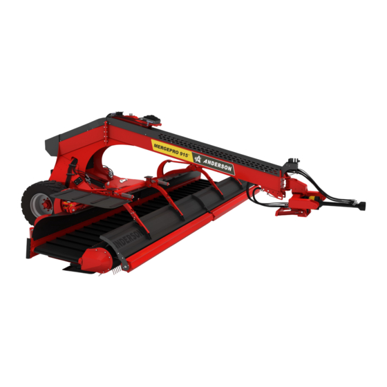
1 Introduction Congratulations! You've just purchased an Anderson hay merger, a quality piece of machinery designed specifically for windrowing. 1.1 Overview The following figures show the main components of the MERGEPRO hay merger: Figure 1 - Main Components of the MERGEPRO Hay Merger Anderson Group Hay Merger –... - Page 10 Table 1 — Description of the Control Box Components Component Description Control screen (see "Controls" on page 51) Power supply cable Hay merger connection cable Fuse CAN/BUS communication cable (to program the hay merger's computer) Control screen On/Off switch Operator's Manual – Hay Merger Anderson Group...
-
Page 11: Technical Specifications
4.63 m (15.2 ft) Conveyor width 0.92 m (36 in) 0.92 m (36 in) Weight when empty 5,000 kg (11,000 lb) 5,850 kg (12,897 lb.) GVWR (gross vehicle weight rating) 8,000 kg (17,637 lbs) 8,000 kg (17,637 lbs) Anderson Group Hay Merger – Operator's Manual... - Page 12 2 double-acting hydraulic control valves (3 with swathboard option) Hydraulic flow: 38 Lpm (10 gpm) Hydraulic pressure: 172 bar (2500 psi) Required -10 °C (14 °F) minimum temperature Below this temperature, the hay merger won't operate in an optimal manner. Operator's Manual – Hay Merger Anderson Group...
-
Page 13: Machine Identification
It displays the following information about your equipment: Model Serial number Empty weight Gross weight (GVWR) Manufacturing year NOTE: You must always have this information on hand when ordering replacement parts or requesting assistance from our customer service department. Anderson Group Hay Merger – Operator's Manual... -
Page 14: Safety And Maintenance Pictograms
Ensure that you see and understand them. Table 4 — Safety and Maintenance Pictograms Pictogram Meaning Warning! Check the tightening torque on the lug nuts. Lubricate with grease at the frequency recommended in Section Greasing on page Operator's Manual – Hay Merger Anderson Group... - Page 15 Warning! Before welding the equipment or working on the electrical system, disconnect the tractor power supply and disconnect and remove the control module. Warning! Risk of crushing hands. Warning! Pressurized hydraulic hoses. See Section Maintenance on page 85. Anderson Group Hay Merger – Operator's Manual...
- Page 16 Important: After adjusting the belt tension, check that the belt is positioned above the side guides on both sides. Operator's Manual – Hay Merger Anderson Group...
- Page 17 Operating angle of the pick-up unit relative to the ground (see section "Adjusting the angle of the pick-up units" on page 44) Functions of the hydraulic controls on the main valve (see "Hydraulic controls" on page 69). Anderson Group Hay Merger – Operator's Manual...
-
Page 19: Safety Precautions
2 Safety precautions Your Anderson machine was designed to minimize risk to the operator. Nevertheless, it must only be used for its intended purpose. Misuse of the machine may result in injury to the operator. The machine has a hydraulic system and moving mechanical parts. All these components can cause serious or even fatal injury to people and animals. - Page 20 2.1.5 Warnings/pictograms The warnings and pictograms on the machine provide safety information and help prevent accidents. Ensure that the warnings and pictograms remain clean and clearly visible. In the event of Operator's Manual – Hay Merger Anderson Group...
-
Page 21: Safety Tips For Transport
Ask for the power line to be disconnected. 2.2 Safety tips for transport Before travelling public roads, lock windguards (2) with the locking devices (4) provided. Anderson Group Hay Merger – Operator's Manual... -
Page 22: Safety Tips For Hitching
(see the tractor manufacturer's instructions). Do not exceed the maximum load permitted on the hitching points. If necessary, place ballast weights on the supports provided in accordance with the tractor manufacturer’s instructions. Operator's Manual – Hay Merger Anderson Group... -
Page 23: Safety Tips For Maintenance And Repairs
Move any combustible materials (hay, organic matter, gasoline, etc.) away from the area before welding. Eliminate any risk of fire. 2.4.3 Wiring Before starting work on the electrical system, disconnect the battery or electrical power supply. Anderson Group Hay Merger – Operator's Manual... -
Page 24: Safety Tips For The Pto And Drive Shaft
2.5 Safety tips for the PTO and drive shaft 2.5.1 Tractor PTO and machine drive shaft Before use, check that the speed and rotation direction of the tractor’s PTO are compatible with the intended use of the machine. Operator's Manual – Hay Merger Anderson Group... -
Page 25: Waste Recovery
Return used fluids to a collection and reprocessing centre so that they are recycled or disposed of in accordance with legislation. Stockpiling, abandoning or dumping tires is prohibited, as is burning them outdoors. Return them to an approved distributor or collector. Anderson Group Hay Merger – Operator's Manual... -
Page 27: Getting Started
1. Unbolt bolts A (2 bolts per pair of skid shoes) (Figure 6). Support the pair of skid shoes using lifting equipment. 2. Unbolt bolts B (2 bolts per pair of skid shoes) (Figure 6). Figure 6 — Skid Shoes in Transport Position Anderson Group Hay Merger – Operator's Manual... - Page 28 4. Remove bolts and nuts B (6 bolts and 6 nuts per conveyor) (Figure 8). 5. Remove bolts and nuts A (4 bolts and 4 nuts per conveyor), and remove the steel plates marked "TO BE REMOVED" (2 plates per conveyor) (Figure 8). Operator's Manual – Hay Merger Anderson Group...
- Page 29 3.1.3 Reposition the axles (MERGEPRO 1060) When two MERGEPRO are delivered on the same semi-trailer, their axles are positioned towards the front. To get them into position for use, they must be moved back. Anderson Group Hay Merger – Operator's Manual...
-
Page 30: Hitching To The Tractor And Unhitching
Figure 10 - Moving the Axle to its Operating Position 3.2 Hitching to the tractor and unhitching Use extreme caution when hitching and unhitching the equipment. Before proceeding, securely immobilize the equipment with the devices provided. Operator's Manual – Hay Merger Anderson Group... - Page 31 35). NOTE: Anderson equipment intended for the European market are equipped with a safety device that prevents unauthorized use. This device consists of a chain passed through the ring of the coupler head and secured by a padlock, to meet the requirements of Regulation (EU) 167/2013 (Annex XVIII of the Delegated Regulation (EU) 2015/208).
- Page 32 1. Lower the tractor's lift arms. 2. Position the lift arms so their hooks are as close as possible to underneath the hay merger's hitch pins. 3. Raise the tractor's lift arms to catch the hitch pins. Operator's Manual – Hay Merger Anderson Group...
- Page 33 7. Unlock the parking stand by removing the 2 retaining pins (B) and the 2 axis pins (A). Figure 12 — Parking Stand in Use 8. Lift the parking stand and lock it in the stowed position using axis pins (A) and retaining pins (B). Anderson Group Hay Merger – Operator's Manual...
- Page 34 If not hitched properly, the equipment could come loose while it is being transported or used. This could injure the operator or other people, or damage the tractor or equipment. Operator's Manual – Hay Merger Anderson Group...
-
Page 35: Connecting The Hydraulic And Electrical Systems
3. Install the control screen in the tractor cab using the RAM® clamp or RAM® ball. One or the other is supplied with the machine, depending on the cab configuration. Anderson Group Hay Merger – Operator's Manual... - Page 36 (if applicable) to ensure that each hose is connected properly. 10. Operate the tractor's PTO to ensure both pick-up units work properly. NOTE: The conveyors must be in working position to start the conveyors and pickups. Operator's Manual – Hay Merger Anderson Group...
-
Page 37: Connecting The Drive Shaft
A drive shaft that is too long for the tractor’s PTO could damage the drive shaft and PTO. A drive shaft that is too short could also be damaged. Anderson Group Hay Merger – Operator's Manual... - Page 38 For a semi-mounted machine, the tractor aligned with the machine). 3. Check that the maximum length during use is less than 0.9 m (35.5 in). Operator's Manual – Hay Merger Anderson Group...
-
Page 39: Preliminary Maintenance
3. Gradually increase the tractor's engine speed until you reach a speed of 800 RPM on the PTO. 4. On the control screen, reverse the direction of the conveyors' rotation (see "Main menu" on page 52). 5. Extend the conveyors to their maximum. Anderson Group Hay Merger – Operator's Manual... -
Page 40: Connecting The Hydraulic Brakes (Option)
103). To disconnect the hydraulic brakes from the tractor: 1. By rotating the pin back and forth a few times, actuate the emergency valve to relieve the pressure in the hydraulic brake accumulator. Operator's Manual – Hay Merger Anderson Group... - Page 41 2. Ensure that the straight arm of the pin is vertical and is touching the emergency valve. 3. Disconnect the hydraulic hose from the tractor brakes. Figure 18 — Hydraulic Brakes Figure 19 — Pin and Emergency Valve for the Hydraulic Brakes Anderson Group Hay Merger – Operator's Manual...
- Page 42 NOTE: If, following an impact, the hay merger detaches from the tractor and the emergency valve triggers the emergency brakes, it is recommended that you replace the cable with a new one. Operator's Manual – Hay Merger Anderson Group...
-
Page 43: Adjustments
To adjust the distance between the tines and the ground, adjust the length of the upper linkage (A): Extend the linkage to bring the tines closer to the ground. Shorten the linkage to lift the tines farther from the ground. Anderson Group Hay Merger – Operator's Manual... - Page 44 2. Place the skid shoe so that you can put bolt (A) in the other hole (B). 3. Replace and tighten nut and bolt (A). 4. Repeat this adjustment for the 3 other skid shoes. Operator's Manual – Hay Merger Anderson Group...
-
Page 45: Adjusting The Windguard Tension
There are 4 nuts total (2 per pick-up unit). Always apply the same torque to all 4 nuts. Do not adjust nut (B), located inside the spring. It ensures that the windguard doesn't collide with the tines of the pickup. Anderson Group Hay Merger – Operator's Manual... -
Page 46: Adjusting The Windguards
The original position is the optimum adjustment and is suitable for most forages. Always ensure the angle and height are the same for both windguards. Figure 24 — Original Position of the Windguards Operator's Manual – Hay Merger Anderson Group... - Page 47 (E) on the bolts. 4. Do the same for the other arm. 5. Repeat the procedure for the windguard on the other side of the machine. Figure 25 — Adjusting the Windguards Anderson Group Hay Merger – Operator's Manual...
-
Page 48: Adjusting The Ground Pressure Of The Pick-Up Units
The ground pressure of the pick-up units is inversely proportional to the pressure of the hydraulic suspension. For each pick-up unit, the hydraulic suspension pressure should be set at 70 bar (1000 psi). The hydraulic suspension pressure is displayed on the pressure gauge located near the hydraulic accumulator. Operator's Manual – Hay Merger Anderson Group... - Page 49 9. Repeat steps 4 through 8 to validate the pressure. 10. Close the needle valves (A), located behind the pressure gauges (B). Figure 27 — Adjusting the Ground Pressure of the Pick-Up Units Anderson Group Hay Merger – Operator's Manual...
-
Page 51: Operation
Activate the left or right swathboard (optional). Activate the lifting (raise/lower) or translation (extend/bring together) of the conveyors. Open the settings menu. Allows you to navigate the menus. Reverse the rotation direction of the left or right conveyor. Anderson Group Hay Merger – Operator's Manual... - Page 52 5.1.1 Main menu The control screen's main menu (Figure 29) is used to control the hay merger's position. The main menu also provides access to the settings menu. Figure 29 – Main Menu Operator's Manual – Hay Merger Anderson Group...
- Page 53 Opens the settings menu (see "Settings menu" on page 54). Reverse the rotation direction of the left or right conveyor. Reverse the rotation direction of both conveyors simultaneously. Turns the work lights on and off. Start Stop Tractor power take-off (PTO) speed Anderson Group Hay Merger – Operator's Manual...
- Page 54 Time remaining before various maintenance operations must be performed (see Figure 31 and Figure 32). FORCE SENSORS Used to force a change of state for one or more defective sensors (see "Forcing a defective sensor to change state" on page 73). Operator's Manual – Hay Merger Anderson Group...
- Page 55 The SCREEN P.O.V INVERSION option changes the view of the hay merger shown on the screen: ENABLED: The hay merger is shown from the rear. DISABLED: The hay merger is shown from the front. See Figure 34. Anderson Group Hay Merger – Operator's Manual...
- Page 56 NOTE: These values are calculated only when a PTO or hydraulic pressure is detected. See Figure 35. INPUTS / Displays the state of the sensors (see "Sensors" on page 72). OUTPUTS Figure 31 — MAINTENANCE page 1/2 Figure 32 — MAINTENANCE page 2/2 Operator's Manual – Hay Merger Anderson Group...
- Page 57 Figure 33 — MACHINE SETTINGS page Figure 34 — DISPLAY SETTINGS page Figure 35 — SYSTEM INFO page Anderson Group Hay Merger – Operator's Manual...
-
Page 58: Windrowing
Figure 38 — Sensor Status INPUTS / OUTPUTS page 3/3 5.2 Windrowing Before starting work, ensure that no one is in the machine's area of movement. If necessary, move all people a safe distance from the area. Operator's Manual – Hay Merger Anderson Group... - Page 59 3. To make a center swath, select the mode on the control screen, and use the tractor's hydraulic controls to extend the conveyors all the way out (see "Selecting the windrow delivery mode" on page 60). Anderson Group Hay Merger – Operator's Manual...
- Page 60 Before swathing, you must first choose a delivery mode. The delivery mode depends on the position of the pick-up units (extended or brought together) and the rotation direction of the conveyors (left or right). The following table shows the various delivery modes available. Operator's Manual – Hay Merger Anderson Group...
- Page 61 Table 9 — Delivery Modes Position of the Location of windrow(s) pick-up units Pick-up units Windrow on the right brought together Windrow on the left Windrows on both sides Anderson Group Hay Merger – Operator's Manual...
- Page 62 Position of the Location of windrow(s) pick-up units Pick-up units Windrow in the center extended Windrows in the center and on the right Windrows in the center and on the left Windrows on both sides Operator's Manual – Hay Merger Anderson Group...
- Page 63 2. Using the tractor's hydraulic controls, completely raise the pickup unit that won't be used. On the screen, the machine will be shown as in the following figures, depending on the pick-up unit raised. Figure 39 – Single Conveyor Operation - Left Conveyor Anderson Group Hay Merger – Operator's Manual...
-
Page 64: Forward Speed
The machine can operate at speeds up to 28 km/h (18 mph), but the speed must be adapted to the working conditions. To optimize collection, Anderson Group has developed an automatic mode that adjusts the speed of the pick-up units according to the speed of travel. A manual mode is also available. - Page 65 SPEED: Forward speed. Figure 42 – Main Menu - Automatic Mode Anderson Group Hay Merger – Operator's Manual...
- Page 66 KM/H/MPH: Rotation speed of the pickups and conveyors. The speed can be adjusted with the central up and down arrows, according to the type of hay. SPEED: Forward speed. Figure 44 – Main Menu - Manual Mode Operator's Manual – Hay Merger Anderson Group...
-
Page 67: Using The (Optional) Swathboards
Wait until all moving parts have come to a complete stop. Ensure that no one is in the machine's area of movement. If necessary, move all people a safe distance from the area. Anderson Group Hay Merger – Operator's Manual... - Page 68 4. Raise the conveyors using the tractor's hydraulic controls. Make sure you're in Lift mode first. When the hay merger is in transport position, it's shown on the display as in Figure 46. Figure 46 – Hay Merger in Transport Position Operator's Manual – Hay Merger Anderson Group...
-
Page 69: Troubleshooting
The hydraulic controls must never be used if the hay merger can be put in motion. Before using the hydraulic controls, ensure that no one will operate the controls at the same time on the tractor. Anderson Group Hay Merger – Operator's Manual... - Page 70 In the event of a failure of the hay merger's electrical system, you can operate your equipment using the devices provided for this purpose. The speed of the conveyors and pickups will no longer vary according to the forward speed. Operator's Manual – Hay Merger Anderson Group...
- Page 71 2. Go to the back of the machine and open the guard that covers the main valve. 3. Operate the levers according to the desired direction of conveyor rotation, then lock the levers with the locking devices (A). 4. Restart the tractor. Anderson Group Hay Merger – Operator's Manual...
-
Page 72: Sensors
6.3.1 Defective sensors The lights on the sensors show that they are working properly. However, a sensor may appear to be working correctly (light on) even though no signal is being emitted. Operator's Manual – Hay Merger Anderson Group... - Page 73 This allows you to continue to perform manoeuvres that can only be performed when various sensors are in a specific state (ON or OFF) (see "Maneuvers requiring certain sensor states" on page 75). Anderson Group Hay Merger – Operator's Manual...
- Page 74 1. On the control screen's main menu, select to open the settings menu. 2. Using the arrow keys, navigate to FORCE SENSORS, then press Figure 51 — Force Sensors Option in the Settings Menu Operator's Manual – Hay Merger Anderson Group...
- Page 75 4. Make sure the machine image on the main menu matches the real machine. Maneuvers requiring certain sensor states The following table shows the state the conveyor position sensors must be in to perform certain maneuvers. Anderson Group Hay Merger – Operator's Manual...
- Page 76 ON conveyor's lift arm lowered DOW_RC ON or Right forced ON conveyor's lift arm lowered RET_LC Not forced Left conveyor brought to center RET_RC Not forced Right conveyor brought to center Operator's Manual – Hay Merger Anderson Group...
- Page 77 Detects if right conveyor is at bottom Figure 54 C2P01 MC024-C1P07 RET_RC Detects if right conveyor is in central position Figure 54 (brought together) MC024-C1P10 MERG_ Measures the MERGEPRO's forward speed Figure 53 Anderson Group Hay Merger – Operator's Manual...
- Page 78 Measures the hydraulic pressure Figure 53 MC024-MC024- OIL_ Measures the hydraulic oil temperature Figure 53 C2P02 TEMP MC024-C1P12 LOW- _ OIL Detects if hydraulic oil is at low level Figure 53 Figure 53 — Sensors (1) Operator's Manual – Hay Merger Anderson Group...
-
Page 79: Errors
The following table lists the error codes that may appear on the control screen. Table 12 — Errors ERROR Description/Action CODE RPM_PTO sensor error. Check the sensor's condition, fit, and connection. Replace if necessary. Anderson Group Hay Merger – Operator's Manual... - Page 80 Electrical problem: Short circuit between the MC024-C2P09 sensor and the "Counterclockwise oil cooler" relay. Electrical problem: Open circuit between the MC024-C2P10 sensor and the "LED light" relay. Inspect the wires and LEDs, and replace them if necessary. Operator's Manual – Hay Merger Anderson Group...
- Page 81 (max. 85 °C). Oil level in the oil tank is too low. Add TDH hydraulic oil. The machine will work again once the oil level is restored. PTO stopped. Start the PTO. Anderson Group Hay Merger – Operator's Manual...
-
Page 82: Common Problems
Section How to reach us on page 5 for our contact information). NOTE: An interactive diagnostic tool ( chatbot ) is available on the grpanderson.com website and on the Anderson Group mobile app, available on Google Play and the App Store. Table 13 — Common Problems Problem... - Page 83 The hydraulic unit is leaking oil. The seals inside Replace the seals inside the the hydraulic unit hydraulic unit. are defective. The system is losing pressure. The filters are Replace the filters. blocked. Anderson Group Hay Merger – Operator's Manual...
- Page 84 The oil is too dirty. Change the oil. hydraulic properties. The oil cooler is Clean the oil cooler. too dirty. For any other problems, please contact your dealer or our technical service department. Operator's Manual – Hay Merger Anderson Group...
-
Page 85: Maintenance
During maintenance, comply with standard safety rules. See Section Safety tips for maintenance and repairs on page 23 for these rules. It is important to follow the recommended maintenance schedule. Anderson Group Hay Merger – Operator's Manual... -
Page 86: Maintenance Schedule
Replace the high-pressure oil filter 7.11 Replace the return oil filter 7.11 Changing the hydraulic oil 7.11 Remove any accumulated debris (hay, 7.11 dust, etc.) Grease all greasing points, except the pickup bearings Operator's Manual – Hay Merger Anderson Group... - Page 87 Check the brake slack and wear Adjust the brake slack Check that all hoses are in good condition 7.10 Grease the wheel bearings Replace the fill cap on the hydraulic tank Clean the suction oil filter Anderson Group Hay Merger – Operator's Manual...
-
Page 88: Greasing
Your hay merger must be greased with a gun where indicated by the label in the following figure: Figure 55 — Greasing Point Marker NOTE: Anderson Group recommends using synthetic grease. Table 15 — Greasing Frequency Part (number of greasing points) Every 50 hours of use... - Page 89 Figure 56 — Greasing Points (1) Figure 57 — Greasing Points (2) Anderson Group Hay Merger – Operator's Manual...
- Page 90 4. For the bearings located towards the outside of the machine, unscrew screw (C) on the 5 band (B) from the end of the machine, then unfold the band to access the grease nipple. Operator's Manual – Hay Merger Anderson Group...
-
Page 91: Belt Tension
Before working on the machine, disengage the power take- off (PTO), stop the tractor engine, remove the ignition key, wait for all moving parts to come to a complete stop, and apply the hand brake. Anderson Group Hay Merger – Operator's Manual... - Page 92 The procedure to adjust the belt tension is identical for both conveyors. Figure 61 — Tensioner Locations 7.3.1 Adjusting the tension of the belt 1. Pull the tensioner lever (A) to release the tension adjustment system. 2. Remove pin (B). Operator's Manual – Hay Merger Anderson Group...
-
Page 93: Replacing Pickup Tines
7.4 Replacing pickup tines If several tines on a pickup are worn or broken, they must be replaced. 1. Put the machine in a working position. 2. Extend the pick-up units away from each other. Anderson Group Hay Merger – Operator's Manual... -
Page 94: Tire Pressure
6. Repeat steps 3 to 5 for all bands with tines needing to be replaced. Figure 63 - Screw to remove when replacing a band's tines 7.5 Tire pressure Check the tire pressure before each use. The pressure should be 4 bar (58 psi). Operator's Manual – Hay Merger Anderson Group... -
Page 95: Maintaining And Adjusting The Axles
350 (+30/0) N m (258 (+22/0) 600 mm (24 60 kg (132 lb.-ft.) in.) lb.) 1 1/16 in. 5/8-18 270 (+20/0) N m (200 (+15/0) 450 mm (18 60 kg (132 lb.-ft.) in.) lb.) Anderson Group Hay Merger – Operator's Manual... - Page 96 Regularly check that the hubcaps are firmly in place and are in perfect condition. Immediately replace missing or damaged hubcaps to prevent dirt from getting inside a hub, which could damage the bearings. Operator's Manual – Hay Merger Anderson Group...
- Page 97 1. Lift the axle until the wheel is no longer resting on the ground. For large wheels, remove the wheel to make it easier to feel the play and see what you are adjusting. 2. Remove the hubcap. 3. Remove the cotter pin or hair pin clip from the castle nut. Anderson Group Hay Merger – Operator's Manual...
- Page 98 Once the wheel is back on, turn it slightly. The wheel should come to rest with a slight rocking movement. Figure 66 — Wheel Bearing Table 17 — Wheel Bearing Components Component Spindle Oil seal Inner bearing Operator's Manual – Hay Merger Anderson Group...
- Page 99 3. Remove the wheel and release the brake. NOTE: Make sure that the vehicle is completely immobilized. 4. Remove the hubcap. 5. Remove the cotter pin or hair pin clip from the castle nut, and then remove the castle nut. Anderson Group Hay Merger – Operator's Manual...
- Page 100 9. Lock the castle nut with a new cotter pin or the hair pin clip, as appropriate. 10. For hubs without grease retainers, fill the hubcap with grease. 11. Put the hubcap back on. Operator's Manual – Hay Merger Anderson Group...
- Page 101 1. Remove the wheel bearings as described in "Lubricating the wheel bearings" on page 99. 2. Remove the outer races of the bearings, which are inside the hub (Figure 69). NOTE: Note the positions of the outer races and grease retainers for reassembly. Anderson Group Hay Merger – Operator's Manual...
- Page 102 (in the correct direction). Make sure it is centred and remains in place throughout the process of putting the outer race back in. 4. Perform a final check. Figure 69 — Outer Race Figure 70 — Inserting New Outer Races Operator's Manual – Hay Merger Anderson Group...
-
Page 103: Maintaining And Adjusting The Brakes (Option)
You will need to take up the slack when the push rod stroke is approximately 2/3 of the maximum travel. To do so, move the lever one or more notches relative to the cam. Anderson Group Hay Merger – Operator's Manual... - Page 104 7.7.4 Replacing the brake shoes The brake shoes must be replaced when the lining has reached the minimum thickness. Use this opportunity to grease the wheel bearings (see "Lubricating the wheel bearings" on page 99). Operator's Manual – Hay Merger Anderson Group...
- Page 105 To make it easier, you can put a tube handle on the lever (Figure 73). The shoes will then make contact with the drum. 2. Tighten the anchor pin while maintaining pressure on the lever. 3. Replace the pin if using a cotter pin. Anderson Group Hay Merger – Operator's Manual...
-
Page 106: Filter Maintenance
Check the condition. If the filter is Every 7.8, E dirty, clean or replace it. 50 hours of Fill cap filter on the Replace Every 7.8, B hydraulic tank 900 hours of Suction oil filter Clean Every 7.8, C 900 hours of Operator's Manual – Hay Merger Anderson Group... -
Page 107: Oil Levels And Leaks
360 L (95 (transmission/differential hours of use. US gal) Subsequent oil changes: hydraulic oil) Every 900 hours of use. Gearbox oil 80W90 Oil changes: Every 200 hours of 0.5 L (0.13 use. US gal) Anderson Group Hay Merger – Operator's Manual... -
Page 108: Cleaning
Before re-tensioning a belt, make sure the belt is positioned over the lateral guides on either side of the conveyor. Figure 75 — Lateral Guides for the Conveyor Belt Every 6 months, Anderson Group recommends a more thorough cleaning. Operator's Manual – Hay Merger Anderson Group... - Page 109 9. Clean the belt with compressed air, and scrape the rollers with a scraper. 10. If you need to replace worn or damaged parts, use genuine ANDERSON parts. 11. Repeat the procedure for the belt on the other side of the machine.
-
Page 110: Storage
If you don't plan to use the hay merger for a long time, store it on a flat surface. For your safety, chock the wheels to prevent the hay merger from moving. NOTE: Anderson Group strongly recommends cleaning and performing general maintenance on the machine before storing it for long periods. - Page 111 NOTE: Anderson machines intended for the European market are equipped with a safety device that prevents unauthorized use. This device consists of a chain passed through the ring of the coupler head and secured by a padlock, to meet the requirements of Regulation (EU) 167/2013 (Annex XVIII of the Delegated Regulation (EU) 2015/208).
- Page 112 ANDERSON GROUP 5125 De la Plaisance St. Chesterville, QC G0P 1J0 CANADA Email: support@grpanderson.com Phone: 1-819-382-2952 Fax: 1-819-382-2218 grpanderson.com...
Need help?
Do you have a question about the Hay Merger MERGEPRO 915 and is the answer not in the manual?
Questions and answers