Table of Contents
Advertisement
Quick Links
● Thank you for your Yamato Scientific BM series Water Bath purchase.
● For proper use of this unit, please read the instruction manual and warranty thoroughly before
operation. Keep both for any future references.
WATER BATH
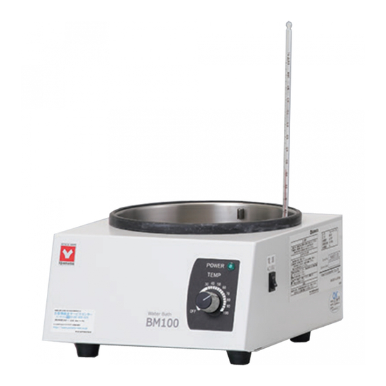
BM100
BM200
(100V)
Instruction Manual
Second Edition
Read and apprehend important warnings in this
instruction manual prior to use.
This paper has been printed on recycled paper.
No.AC5-9709-11-BM
Advertisement
Chapters
Table of Contents
Troubleshooting

Subscribe to Our Youtube Channel
Related Manuals for Yamato BM100


Summary of Contents for Yamato BM100
- Page 1 (100V) Instruction Manual Second Edition ● Thank you for your Yamato Scientific BM series Water Bath purchase. ● For proper use of this unit, please read the instruction manual and warranty thoroughly before operation. Keep both for any future references.
-
Page 3: Table Of Contents
1. Specifications ............................. 1 2. Safety Information .......................... 2-5 Safety Symbols…………………………………………………………………………..2 Safety Precautions…………………………………………………………………….3-4 Hazardous Materials…………………………………………………………………….5 3. Identification of Parts ........................6-9 BM100…………………………………………………………………………………….6 BM200…………………………………………………………………………………….7 Sample : Combined with RE200……………………………………………………….8 Sample : Combined with RE500……………………………………………………….9 4. How to Operate ..........................10 How to operate………………………………………………………………………….10 Operation after restoration from power failure………………………………………10... -
Page 4: Specifications
● Bar Thermometer (-10℃~110℃ with immersion line) 1 Standard accessories ● Fuse ( BM100 7A, BM200 15A ) 1 ● Instruction manual 1 ● Warranty 1 *1 In case of unloaded operation of bath only. The maximum temperature varies on circumstances and operational conditions. -
Page 5: Safety Information
2. Safety Information Safety Symbols Graphic indications This instruction manual and our products apply various indications for safety. Ignoring these indications can cause such situations as listed below. Read and understand the following warning and caution signs in this manual prior to use. WARNING Indicates the possibility of serious or fatal injury (Note 1). -
Page 6: Safety Precautions
If smoke or any strange odor should disburse from this unit, turn the power off immediately and pull out the main power cord. Then contact Yamato Scientific. Neglecting this procedure can result in fire or electric shock. Never try repairing the unit yourself. - Page 7 Safety Information Safety Precautions If it begins to thunder… If it begins to thunder, turn both the breaker and the main power off. Neglecting this procedure can result in fire, electric shock or other troubles due to thunderbolts. Indication of temperature and operational range. This unit is not equipped with a stirring function.
-
Page 8: Hazardous Materials
Safety Information Hazardous Materials Hazardous material are listed below. Never use these materials as samples or heat media. Nitroglycol, Nitroglycerin, Nitrocellulose, and other explosive nitric esters. Trinitrobenzene, Trinitrotoluene, Picric acid, and other explosive nitro Explosive Explosive compounds. Substance Peracetic acid, Methyl ethyl ketone peroxide, Benzoyl peroxide, and other organic peroxides. -
Page 9: Identification Of Parts
3. Identification of Parts BM100 BM100 Thermometer Power Switch Power Lamp Temperature Dial Fuse Power Cord Thermometer Holder Sensor Heater... -
Page 10: Bm200
Identification of Parts BM200 BM200 Thermometer Power Switch Drain Plug Power Lamp Temperature Dial Service Outlet Fuse Power Cord Heater Thermometer Holder Sensor... -
Page 11: Sample : Combined With Re200
Identification of Parts Sample : Combined with RE200 Combination with RE200 Drawing 1 Drawing 2 According to the position or space to set the bath and the body, the arm jack can be set in the front (drawing 1)or on the right side (drawing 2) as shown above. -
Page 12: Sample : Combined With Re500
Identification of Parts Sample : Combined with RE500 Combination with RE500... -
Page 13: How To Operate
Power Lamp Temperature Dial 1. Pour adequate water (3000ml for BM100, 5000ml for BM200) into the tank, and place a thermometer in the holder. 2. Connect the unit securely to a power source with AC100V. Never fail to ground the unit. Then set the temperature dial to the temperature to operate and turn on the power switch. -
Page 14: Maintenance
● If there is no power failure ● If the fuse blows The temperature does not rise or is ●If the temperature setting knob is fixed tightly different from the set value when the power lamp is on. If you have any question, contact Yamato Scientific. -
Page 15: After Sale Service And Warranty
Warranty card (attached separately) Warranty card will be handed by dealer or Yamato personnel upon delivery and installation, or will be attached to equipment if no one from dealer or Yamato is to be present at delivery and installation. Register warranty card at https://www.yamato-net.co.jp/support/warranty.htm ... -
Page 16: List Of Exchange Parts
7. List of Exchange Parts Name of Parts Parts Number Application Specification FN30C-125V7A Φ6.4×30 Fuse LT00036151 BM100 MF61NR15 Φ6.35×31.8 250V 15A Fuse 2100060001 BM200 Thermal Fuse LT00033516 BM100/200 E5A51077C 250V 16A Thermometer 5020016003 BM100/200 Drain Plug 7320016005 BM200 O-Ring 4210026020 BM200 P12.5 Baiton... -
Page 17: Wiring Diagram
8. Wiring Diagram BM100 BM200 ① ⑤ ⑥ ② ③ ④ ⑦ Symbol Name of Parts Symbol Name of Parts Fuse Service Outlet Heater Power Switch Power Lamp Terminal Power Plug Thermoregulator Thermofuse... - Page 18 Be sure to use the unit strictly following the handling and operating instructions in this operating instruction. Yamato Scientific Co., Ltd. assumes no responsibility for an accident or a malfunction caused by use of this product in any way not specified in this operating instruction.
- Page 19 BO601 Instruction Manual - First Edition - Thank you for choosing BM/BO Series Baths from Yamato Scientific Co., Ltd. For proper equipment operation, please read this instruction manual thoroughly before use. Always keep equipment documentation safe and close at hand for convenient future reference.
- Page 20 Contents 1. SAFETY PRECAUTIONS ..............1 Explanation of Safety Symbols ..................1 Symbol Glossary ......................2 Warnings & Cautions ....................3 2. PRE-OPERATION PROCEDURES ............. 5 Placement Precautions & Preparations ................ 5 Prior Confirmation ......................8 3.
-
Page 21: Safety Precautions
1. SAFETY PRECAUTIONS Explanation of Safety Symbols A Word Regarding Symbols Various symbols are provided throughout this text and on equipment to ensure safe operation. Failure to comprehend the operational hazards and risks associated with these symbols may lead to adverse results as explained below. -
Page 22: Symbol Glossary
1. SAFETY PRECAUTIONS Symbol Glossary Warning General Danger!: Danger!: Danger!: Danger!: Warning High Voltage Extremely Hot Moving Parts Blast Hazard Caution Caution: Caution: Do Not Caution: Burn Caution: May General Caution Electrical Shock Heat Without Hazard! Leak Water! Hazard! Water! Caution: Water Caution: Toxic Only... -
Page 23: Warnings & Cautions
1. SAFETY PRECAUTIONS Warnings & Cautions WARNING! Never operate equipment near combustible gases/fumes. Do not install or operate BM/BO series units near flammable or explosive gases/fumes. Unit is NOT fire or blast resistant. Negligent use could cause a fire/explosion. See “List of Hazardous Substances” (P.44). Always ground equipment. - Page 24 1. SAFETY PRECAUTIONS Warnings & Cautions CAUTION! DO NOT operate equipment during thunderstorm. In the event of a thunderstorm, terminate operation and turn off main power switch immediately. A direct lightning strike may cause damage to equipment, or result in fire or electric shock. Power Outages Operation stops when power failures occur.
-
Page 25: Pre-Operation Procedures
2. PRE-OPERATION PROCEDURES Placement Precautions & Preparations 1. Ground wire MUST be connected properly. Ground wire must be connected to a proper grounding line or teminal in order to prevent electric shock. Never connect ground wire to gas lines or water pipes. ... - Page 26 2. PRE-OPERATION PROCEDURES Placement Precautions & Preparations 3. Place in a location free of flammables and explosives. Never place near flammables or explosives. This unit is NOT fire or blast resistant. Simply switching the main power switch “ON” or “OFF” can produce a spark, which could be relayed during operation, causing a fire or explosion when near flammable or explosive fluids, chemicals or gases/fumes.
- Page 27 Failure to do so may result in fire or electric shock. Contact a local dealer or Yamato sales office for information about replacing power cable if it is damaged. Always connect power cable to appropriate facility outlet or terminal.
-
Page 28: Prior Confirmation
2. PRE-OPERATION PROCEDURES Prior Confirmation BM401water bath operation precautions: Exercise caution in regard to the following. ① Connect unit to a power outlet having sufficient capacity. BM401: 100 to 120V AC. ② Do not move unit while in operation. ③ Avoid touching hot surface areas or bath fluid during operation. ④... - Page 29 2. PRE-OPERATION PROCEDURES Prior Confirmation Fluid medium for BO601 oil bath Maximum operating temperature for BO601 model oil baths is 180°C. Use heat-resistant dimethyl silicon oil for open system heat transfer only, and Kinematic viscosity of 50mm /s (cSt) or less. Recommended: KF-96-50cs silicon oil by Shinetsu Science Industries Co., Ltd.
- Page 30 2. PRE-OPERATION PROCEDURES Prior Confirmation Bath container water/oil supply precautions. Use caution in regard to the following when adding water or oil. BM401 water supply Fill so that reservoir does not overflow when specimen flask/beakers are submersed. Wash reservoir portion of unit regularly with water to keep it clean. Before setup, remove dirt and other contaminants from bath interior, and also from the outer surface.
- Page 31 2. PRE-OPERATION PROCEDURES Prior Confirmation Heater Baffle When inserting the heater baffle into the reservoir, be sure that one of the 6 side notches lines up with the sensor and that the sensor does not contact the baffle. When using heater baffle as a platform to support beakers or other specimen ...
-
Page 32: Component Names & Functions
3. COMPONENT NAMES & FUNCTIONS Unit Overview Shown in combination with RE200 Depending on available space and access, the lift lever may be positioned out in front (figure 1) or behind (figure 2). - Page 33 3. COMPONENT NAMES & FUNCTIONS Unit Overview External Views...
- Page 34 3. COMPONENT NAMES & FUNCTIONS Unit Overview...
-
Page 35: Control Panel
3. COMPONENT NAMES & FUNCTIONS Control Panel Item Description Normally displays temperature reservoir. Depending on panel operation, times and other Temperature display values may be displayed. When an error occurs, the error code is displayed. 2 Heater lamp Illuminates whenever heater is drawing power. 3 Up arrow key Pressed to increase a setting value/parameter 4 Down arrow key... -
Page 36: Display Characters
3. COMPONENT NAMES & FUNCTIONS Display Characters Characters displayed on BM401/BO601 unit control panels are defined in the table below: Character Identifier Meaning Function/Description Timer selection menu: Selection/standby display for quick auto stop/auto AStP Auto Stop stop operation modes Selection/standby display for auto start operation AStr Auto Start mode... -
Page 37: Operation Procedures
4. OPERATION PROCEDURES Operation Modes & Functions BM/BO series operation modes are outlined in the table below: Name Description Page Constant Temp Mode Set desired temperature using △▽. Press and hold to start operation. Press again to stop operation. Quick Auto Stop Press while constant temp mode is running. - Page 38 4. OPERATION PROCEDURES Operation Modes & Functions BM/BO maintenance functions are outlined in the table below. To enter the maintenance menu, press and hold TIMER for four seconds. Name Description Page Keypad Lock This function prevents changes to temperature and other settings by disabling the keypad during operation.
-
Page 39: Mode & Function Flow
4. OPERATION PROCEDURES Mode & Function Flow... -
Page 40: Constant (Fixed) Temperature Mode
4. OPERATION PROCEDURES Constant (Fixed) Temperature Mode Constant Temperature mode is a general use, continuous operation mode (started/stopped manually). Setting Constant Temperature mode Turn power on Turn main power switch ON. Initial screen will appear for approximately 4 seconds and change to standby screen, showing current reservoir temperature. -
Page 41: Quick Auto Stop Mode
4. OPERATION PROCEDURES Quick Auto Stop Mode Quick Auto Stop mode adds auto stop timer function to running constant temperature mode. Stop operation Press for about 1 second to stop operation. Operation lamp turns off. Standby screen (current reservoir temperature) is restored. - Page 42 4. OPERATION PROCEDURES Quick Auto Stop Mode Operation stop Operation stops automatically when time is up. Standby screen is restored. HEATER and operation lamps shut off. To end operation before time is up, press and hold about 1 second. Operation stops and operation lamp shuts off.
-
Page 43: Auto Stop Mode
4. OPERATION PROCEDURES Auto Stop Mode Auto Stop mode allows an automatic stop time to be set in advance of operation. Setting Auto Stop mode Turn power on Turn main power switch ON. Initial screen will appear for approximately 4 seconds and change to standby screen, showing current reservoir temperature. - Page 44 4. OPERATION PROCEDURES Auto Stop Mode Set operation time Pressing either of the keys causes time setting value to begin flashing. Use these keys to set desired operation time. Time setting is shown in 1 minute units from 0 hours, 0 minutes ( ) ~ 99 hours, 59 minutes ( When 100 hours is exceeded, time is displayed in 10...
- Page 45 4. OPERATION PROCEDURES Auto Stop Mode Operation stop Operation stops automatically when time is up. Standby screen is restored. HEATER and operation lamps shut off. To end operation before time is up, press and hold for about 1 second. Operation stops and operation lamp shuts off.
-
Page 46: Auto Start Mode
4. OPERATION PROCEDURES Auto Start Mode Auto Start mode allows an automatic start time to be set in advance of operation. Setting Auto Start Mode Turn power on Turn main power switch ON. Initial screen will appear for approximately 4 seconds and change to standby screen, showing current reservoir temperature. - Page 47 4. OPERATION PROCEDURES Auto Start Mode Set start time Pressing either of the keys causes time setting value to begin flashing. Use these keys to set desired start time. Time setting is shown in 1 minute units from 0 hours, 0 minutes ( ) ~ 99 hours, 59 minutes ( When 100 h ours is exceeded, time is displayed in 10...
- Page 48 4. OPERATION PROCEDURES Auto Start Mode Operation stop Operation must be stopped manually. Press for about 1 second to stop operation. Operation lamp turns off. Standby screen (current reservoir temperature) is restored. Correcting or viewing settings. Use △▽ at any time to correct or view settings. Press either △...
-
Page 49: Overheat Prevention Settings
4. OPERATION PROCEDURES Overheat Prevention Settings BM401/BO601 units feature a built-in safety device to automatically prevent overheating, plus a thermal fuse for redundancy. Overheat prevention device operation: The main overheat prevention device is set to activate at temperature setting plus 40°C, at which point power is cut and is displayed. -
Page 50: Keypad Lock Function
4. OPERATION PROCEDURES Keypad Lock Function The keypad lock function prevents keys from being pressed erroneously during operation. Press for approximately 4 seconds and select from the sub-menu. are displayed alternately. Press to display and either press for 2 seconds or simply wait for unit to automatically revert to standby (about a minute). -
Page 51: Calibration Offset Function
4. OPERATION PROCEDURES Calibration Offset Function Set Calibration Offset The offset function works to correct discrepancies found between the reservoir temperature reading, as seen on the display and actual reservoir temperature, as taken manually, by matching temperature setting to the actual temperature. Enter a positive difference value when the bath temperature is found to be higher than the control panel reading. - Page 52 4. OPERATION PROCEDURES Calibration Offset Function and offset value flash alternately in the display. Enter offset value using Press and hold for 2 seconds or simply wait until display reverts to temperature indication screen. Maximum calibration offset adjustment is 99°C to either side of 0.
-
Page 53: Power Failure Recovery
The service outlet on rear of unit is connected directly to the main power switch, not to the control panel. The power failure recovery function, therefore, does not apply to devices connected to the service outlet. A Yamato rotary evaporator (RE200), in the event of a power interruption, will begin operating once again when power is restored. -
Page 54: Handling Precautions
If unit begins emitting smoke or abnormal odors for reasons unknown, turn off main power switch immediately, disconnect power cable from power supply, and contact a local dealer or Yamato sales office for assistance. Continuing to operate without addressing abnormalities may cause fire or electric shock, resulting in serious injury or death. - Page 55 Read instruction manual thoroughly before use. Likewise, using non-Yamato components to modify, customize or in attempt to otherwise improve unit design is not recommended and...
-
Page 56: Maintenance Procedures
・With the main switch “ON”, depress the test button on the main switch (ELB) using a ball-point pen or other fine-tipped object. If main switch (ELB) shuts off, it is functioning normally. For further assistance, contact a local dealer or the nearest Yamato sales office. -
Page 57: Storage & Disposal
Dispose of or recycle this unit in a responsible and environmentally friendly manner. Yamato Scientific Co., Ltd. strongly recommends disassembling unit, as far as is possible, in order to separate parts and recycle them in contribution to preserving the global environment. -
Page 58: Troubleshooting
8. TROUBLESHOOTING Error Codes Possible error messages are outlined below. Power output to heater is stopped and operator is notified of abnormalities by a corresponding error code in the display. Make note of the code, turn off power and call for service, if necessary. Error Code Cause/Solution Temperature sensor faulty or severed from... -
Page 59: Troubleshooting Guide
8. TROUBLESHOOTING Troubleshooting Guide Symptom Check Unit does not power on. Power cable is not securely inserted into the outlet Power failure is in progress. Water/oil level is low. Control panel remains blank Inadequate voltage from power supply (must be within ±10% after pressing voltage rating) . -
Page 60: Service & Repair
Warranty card will be handed by dealer or Yamato personnel upon delivery and installation, or will be attached to equipment if no one from dealer or Yamato is to be present at delivery and installation. Register warranty card at https://www.yamato-net.co.jp/support/warranty.htm ... -
Page 61: Specifications
10. SPECIFICATIONS Product Water Bath Oil Bath Model BM401 BO601 System Natural convection Usable exterior temperature ±5~35°C AC 100V, 13A (2A service outlet inclusive), 50/60Hz, tolerable Power rating variance: ±10% Temperature control Room temp. +5°C~95°C Room temp. +10°C ~180°C range Temperature setting 0°C ~100℃°C 0°C ~180°C... - Page 62 , 23°C±5°C External temp., 65%RH±20% humidity, 86~106kPa ±5 atmospheric pressure, no test sample load. *2 Yamato standard measurement values, based on KF-96-50cs silicon oil by Shinetsu Science Industries Co., Ltd. in BO601. Measurement values will vary depending on type of silicon oil used. *3 Protrusions excluded.
-
Page 63: Wiring Diagram
11. WIRING DIAGRAM BM401/BO601 Wiring Diagram Glossary Symbol Component Symbol Component ELB1 Earth Leakage Breaker Service Outlet Wiring Terminal Thermal Fuse Heater MAIN Motherboard SSR1 Solid State Relay Display Board Temperature Sensor... -
Page 64: List Of Hazardous Substances
12. LIST OF HAZARDOUS SUBSTANCES Never process any explosive, flammable samples and also samples contained with those substances. ①Nitroglycol, Glycerine trinitrate, Cellulose Nitrate and other explosive nitrate esters ②Trinitrobenzen, Trinitrotoluene, Picric Acid and other explosive nitro compounds ③Acetyl Hydroperoxide, Methyl Ethyl Ketone Peroxide, Benzoyl Peroxide and other organic peroxides ④Metallic Azide, including Sodium Azide, etc. -
Page 65: Setup Checklist
13. SETUP CHECKLIST * Set unit up according to the following: (Confirm optional items or special specifications separately) Installed by Installation approved Assessed Model Serial number Date (company or personnel name) Assessed Item Procedure Instruction manual reference № Specifications Confirm actual items against list of 10. - Page 66 Note ◆ Instruction manual descriptions and specifications are subject to change without notice. ◆ Yamato Scientific Co., Ltd. will replace flawed instruction manuals (pages missing, pages out of order, etc.) upon request. Instruction Manual Water Bath / Oil Bath...
- Page 67 Yamato Scientific Co., Ltd. Printed on recycled paper Thank you for choosing BM/BO Series Baths from Yamato Scientific Co., Ltd. For proper equipment operation, please read this instruction manual thoroughly before use. Always keep equipment documentation safe and close at hand for convenient future reference.
- Page 68 Contents 1. SAFETY PRECAUTIONS ..............1 Explanation of Safety Symbols ..................1 Symbol Glossary ......................2 Warnings & Cautions ..................... 3 2. PRE-OPERATION PROCEDURES ............5 Installation Precautions & Preparations ................. 5 Prior Confirmation ......................9 ...
-
Page 69: Safety Precautions
1. SAFETY PRECAUTIONS Explanation of Safety Symbols A Word Regarding Symbols Various symbols are provided throughout this text and on equipment to ensure safe operation. Failure to comprehend the operational hazards and risks associated with these symbols may lead to adverse results as explained below. -
Page 70: Symbol Glossary
1. SAFETY PRECAUTIONS Symbol Glossary Warning General Danger!: Danger!: Danger!: Danger!: Warning High Voltage Extremely Hot Moving Parts Blast Hazard Caution Caution: Caution: Do Not Caution: Burn Caution: May General Caution Electrical Shock Heat Without Hazard! Leak Water! Hazard! Water! Caution: Water Caution: Toxic Only... -
Page 71: Warnings & Cautions
1. SAFETY PRECAUTIONS Warnings & Cautions WARNING! Never operate equipment near combustible gases/fumes. Do not install or operate BM/BO series units near flammable or explosive gases/fumes. Unit is NOT fire or blast resistant. Negligent use could cause a fire/explosion. See “List of Hazardous Substances” (P.40). - Page 72 1. SAFETY PRECAUTIONS Warnings & Cautions CAUTION! DO NOT operate equipment during thunderstorm. In the event of a thunderstorm, terminate operation and turn off main power switch immediately. A direct lightning strike may cause damage to equipment, or result in fire or electric shock. Power Outages Operation is stopped when power failures occur.
-
Page 73: Pre-Operation Procedures
2. PRE-OPERATION PROCEDURES Installation Precautions & Preparations WARNING! 1. Ground wire MUST be connected properly. Ground wire must be connected to a proper grounding line or teminal in order to prevent electric shock. Never connect ground wire to gas lines or water pipes. ... - Page 74 2. PRE-OPERATION PROCEDURES Installation Precautions & Preparations WARNING! 4. Install in a location free of flammables and explosives. Never install near flammables or explosives. This unit is NOT fire or blast resistant. Simply switching the main power switch “ON” or “OFF” can produce a spark, which could be relayed during operation, causing a fire or explosion when near flammable or explosive fluids, chemicals or gases/fumes.
- Page 75 2. PRE-OPERATION PROCEDURES Installation Precautions & Preparations CAUTION! 6. DO NOT disassemble or modify. Never attempt to disassemble or modify BM/BO units. Doing so may cause equipment malfunction, fire or electric shock. Modification 7. Install on a level surface. Install unit on level and even surface. Failure to do so may cause abnormal vibrations or noise, resulting in possible complications and/or malfunction.
- Page 76 Failure to do so may result in fire or electric shock. Contact a local dealer or Yamato sales office for information about replacing power cable if it is damaged. Always connect power cable to appropriate facility outlet or terminal.
-
Page 77: Prior Confirmation
2. PRE-OPERATION PROCEDURES Prior Confirmation BM500/510 water bath operation precautions: Exercise caution in regard to the following. ① Connect unit to a power outlet having sufficient capacity. ② Do not move unit while in operation. ③ Avoid touching hot surface areas or bath fluid during operation. ④... - Page 78 2. PRE-OPERATION PROCEDURES Prior Confirmation Fluid medium for BO400/BO410 oil baths Maximum operating temperature for BO400/410 model oil baths is 180°C. Use heat-resistant dimethyl silicon oil for open system heat transfer only, and Kinematic viscosity of 50mm /s (cSt) or less. Recommended: TSF458-50 silicon oil for operating temperatures to 200°C, by Toshiba Silicon Co.
- Page 79 2. PRE-OPERATION PROCEDURES Prior Confirmation Bath container water/oil supply precautions. The bath container installed in main unit is removable for easy filling and draining. Use caution in regard to the following when adding water or oil. BM series water bath ...
-
Page 80: Component Names & Functions
3. COMPONENT NAMES & FUNCTIONS Main Unit Overview Front view Removable Bath Container Main Unit (heat-resistant ABS resin) Control Panel Rear view Power switch Power Cable Receptacle Interface for operating bath in combination with rotary evaporator model RE600/800. (Connection cable is supplied with rotary evaporator units) -
Page 81: Control Panel
3. COMPONENT NAMES & FUNCTIONS Control Panel ① ② ③ ⑦ ⑥ ⑧ ⑤ ④ Interface for operating bath in combination with rotary evaporator model RE600/800. (Connection cable is supplied with rotary evaporator units) LEAK LEAK VR600/800 Vacuum controller Name Markings Function ①... - Page 82 Display characters used in BM/BO unit control panels are defined in the table below: Character Identifier Meaning Function/Description Timer selection menu: Selection/standby display for quick auto stop/auto AStP Auto Stop stop operation modes Selection/standby display for auto start operation AStr Auto Start mode Maintenance menu:...
-
Page 83: Operation Procedures
4. OPERATION PROCEDURES Operation Modes & Functions BM/BO series operation modes are outlined in the table below: Name Description Page Set desired temperature with △ ▽ . Constant Temp Mode Press and hold START/STOP to start operation. Press START/STOP again to stop operation. - Page 84 4. OPERATION PROCEDURES Operation Modes & Functions BM/BO maintenance functions are outlined in the table below. To enter the maintenance menu, press and hold TIMER for four seconds. Name Description Page Keypad Lock This function prevents changes to temperature and other setting by disabling the keypad during operation.
-
Page 85: Mode & Function Flow
4. OPERATION PROCEDURES Mode & Function Flow Press & hold 4 seconds for maintenance menu Initial screen displayed for 4 seconds TIMER TIMER TIMER Current temp displayed AStP displayed AStP displayed AStR displayed Set temperature Set timer Set timer Set timer ▲... -
Page 86: Constant Temperature Mode
4. OPERATION PROCEDURES Constant Temperature Mode Constant Temperature mode is a general use, continuous operation mode (started/stopped manually). 1. Turn ON main power switch. Constant temperature operation procedures When power switch is turned ON, display shows initial values for about four seconds before entering standby, which shows current bath temperature in display. -
Page 87: Quick Auto Stop Mode
4. OPERATION PROCEDURES Quick Auto Stop Mode Quick Auto Stop mode adds auto stop timer function to running constant temperature mode. 1. Turn ON main power switch. Quick auto stop operation procedures When power switch is turned ON, display will show initial values for about four seconds before entering standby, which shows current bath temperature in display. - Page 88 4. OPERATION PROCEDURES Quick Auto Stop Mode 6. Stop operation Press and hold START/STOP. Operation stops. The operation and HEATER lamps turn off. Display reverts to standby (current temp). Correcting or viewing settings. Use △▽ at any time to correct or view settings. Press either △...
-
Page 89: Auto Stop Mode
4. OPERATION PROCEDURES Auto Stop Mode Auto Stop mode allows an automatic stop time to be set in advance of operation. 1. Turn ON main power switch. Auto stop operation procedures When power switch is turned ON, display shows initial values for about four seconds before entering standby, which shows current bath temperature in display. - Page 90 4. OPERATION PROCEDURES Auto Stop Mode Correcting or viewing settings. Use △▽ at any time to correct or view settings. Press either △ or ▽once to view temperature setting. Display will automatically revert to temperature reading after 4 seconds. To change the setting, continue operating △▽ until desired temperature is entered.
-
Page 91: Auto Start Mode
4. OPERATION PROCEDURES Auto Start Mode Auto Start mode allows an automatic start time to be set in advance of operation. 1. Turn ON main power switch. Auto start operation procedures When power switch is turned ON, display shows initial values for about four seconds before entering standby, which shows current bath temperature in display. - Page 92 4. OPERATION PROCEDURES Auto Start Mode 5. Stop operation Press and hold START/STOP. Operation stops. Operation and HEATER lamps go out. Display reverts to standby (current temp). Correcting or viewing settings. Use △▽ at any time to correct or view settings. Press either △...
-
Page 93: Overheat Prevention Settings
4. OPERATION PROCEDURES Overheat Prevention Settings BM/BO series units feature a built-in safety device to automatically prevent overheating, plus a thermal fuse for redundancy. How overheating prevention devices work: The main overheat prevention device is set to activate at temperature setting plus 40°C, at which point power is cut and Error 6 is displayed. -
Page 94: Keypad Lock Function
4. OPERATION PROCEDURES Keypad Lock Function Using keypad lock function This function locks the keypad, preventing unwanted interruptions or setting changes during unit operation. Use the TIMER key to set or cancel this function. ① Press and hold TIMER for about four seconds. Select [LocK] to enter menu. -
Page 95: Calibration Offset Function
4. OPERATION PROCEDURES Calibration Offset Function The offset function works to correct discrepancies found between the Set Calibration Offset bath temperature reading, as seen on the display and actual bath temperature, as taken manually, by matching temperature setting to the actual temperature. -
Page 96: Power Failure Recovery
4. OPERATION PROCEDURES Power Failure Recovery This function is to select recovery options, auto return or stop, following a power failure. Press and hold TIMER for about four seconds, then press it repeatedly until [Pon] is shown. Select [on] or [oFF] using △▽. On: continues operation when power is restored. -
Page 97: Handling Precautions
If unit begins emitting smoke or abnormal odors for reasons unknown, turn off main power switch immediately, disconnect power cable from power supply, and contact a local dealer or Yamato sales office for assistance. Continuing to operate without addressing abnormalities may cause fire or electric shock, resulting in serious injury or death. - Page 98 5. HANDLING PRECATIONS CAUTION! 4. Overnight and extended storage. Whenever unit is not in operation, stored overnight or put in storage, always turn off main power switch and disconnect power cable. 5. Use proper bath fluids. Using purified or distilled water in BM model water bath is recommended to prevent mineral deposit accumulation.
-
Page 99: Maintenance Procedures
Deformity, discoloration or other cosmetic damage may result. Wipe contaminants, excess fluids and oil from bath container with a clean, dry cloth. Clean heater and sensor with care. For further assistance, contact a local dealer or the nearest Yamato sales office. -
Page 100: Storage & Disposal
Dispose of or recycle this unit in a responsible and environmentally friendly manner. Yamato Scientific Co., Ltd. strongly recommends disassembling unit, as far as is possible, in order to separate parts and recycle them in contribution to preserving the global environment. -
Page 101: Troubleshooting
8. TROUBLESHOOTING Error Codes Possible error messages are outlined below. Power output to heater is stopped and users are notified of abnormalities by a corresponding error code on the display. Make note of the code, turn off power and call for service, if necessary. Error Code Cause/Solution Temperature sensor faulty or severed from... -
Page 102: Troubleshooting Guide
8. TROUBLESHOOTING Troubleshooting Guide Symptom Check Check to make sure power cable is securely inserted into the receptacle on back of unit Unit does power on. Check to see whether power failure is in progress. Check whether water/oil level is low. Circuit breaker (main power switch) ... -
Page 103: Service & Repair
Requests for Repair When a problem occurs, terminate operation immediately, turn off main power switch and disconnect power cable. Contact a local dealer or Yamato sales office for assistance. The following information is required for all repairs. ● Model name ●... -
Page 104: Specifications
10. SPECIFICATIONS Product Name Water Bath Oil Bath Model BM500 BM510 BO400 BO410 Approx. 4 liters (water/oil added to approx. 30mm from upper lip of bath Bath capacity container) Effective bath capacity Approx. 4 liters Bath container material SUS316 Temperature control Room temp.+5°C~90°C Room temp.+5°C ~180°C range... -
Page 105: Wiring Diagram
11. WIRING DIAGRAM BM500/510 Symbol Part name Circuit protector Terminal block Heater Thermal fuse Solid state relay PLANAR Control board K-thermocouple Display board Bath signal connector Symbol Part name Circuit protector Terminal block Heater Thermal fuse Solid state relay PLANAR Control board K-thermocouple Display board Bath signal connector... - Page 106 11. WIRING DIAGRAM BO400/410 Symbol Part name Circuit protector Terminal block Heater Thermal fuse Solid state relay PLANAR Control board K-thermocouple Display board Bath signal connector Symbol Part name Circuit protector Terminal block Heater Thermal fuse Solid state relay PLANAR Control board K-thermocouple Display board Bath signal connector...
-
Page 107: Replacement Parts
Micro switch to detect heating LT00015305 D2VW-01L1-1M OMRON without water/oil LT00014941 S5C-225MV-(S) Toho Denshi Control board LT00013602 BM/BO PLANAR board Yamato Scientific Display board LT00013603 BM/BO display board Yamato Scientific Sensor LT00026845 BM/BO K-thermocouple Yamato Scientific Pillar fitting LT00012102 Φ15×L20 M4... -
Page 108: List Of Hazardous Substances
13. LIST OF HAZARDOUS SUBSTANCES Never attempt to process explosives, flammables or any items which contain explosives or flammables. EXPLOSIVE Ethylene glycol dinitrate (nitro glycol), Glycerin trinitrate (nitroglycerine), Cellulose nitrate (nitrocellulose), and other explosive nitrate esters Trinitrobenzene, Trinitrotoluene, Trinitrophenol (picric acid), and other explosive EXPLOSIVE: nitro compounds Acetyl hidroperoxide (peracetic acid), Methyl ethyl ketone peroxide, Benzyl... -
Page 109: Setup Checklist
14. SETUP CHECKLIST * Set unit up according to the following: (Confirm optional items or special specifications separately) Installed by Installation approved Assessed Model Serial number Date (company or personnel name) Assessed № Item Procedure Instruction manual reference Specifications Confirm actual items against list of 10. - Page 110 Note ◆ Instruction manual descriptions and specifications are subject to change without notice. ◆ Yamato Scientific Co., Ltd. will replace flawed instruction manuals (pages missing, pages out of order, etc.) upon request. Instruction Manual Water Bath...
Need help?
Do you have a question about the BM100 and is the answer not in the manual?
Questions and answers