Table of Contents
Advertisement
Quick Links
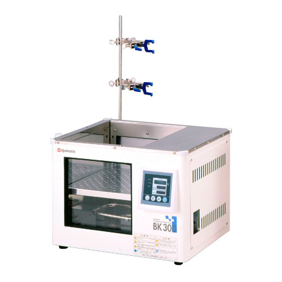
Constant Temperature Water Bath
Model
BK300/400/500/610/710
Instruction Manual
Thank you for purchasing " Constant Temperature
Water Bath, BK Series" of Yamato Scientific Co.,
Ltd.
To use this unit properly, read this "Instruction
Manual" thoroughly before using this unit.
Keep this instruction manual around this unit for
referring at anytime.
WARNING!:
Carefully read and thoroughly understand the
important warning items described in this manual
before using this unit.
Yamato Scientific America Inc.
Santa Clara,CA
- First Edition -
This paper has been printed on recycled paper.
Advertisement
Table of Contents

Subscribe to Our Youtube Channel
Related Manuals for Yamato BK300


Summary of Contents for Yamato BK300
- Page 1 BK300/400/500/610/710 Instruction Manual - First Edition - Thank you for purchasing " Constant Temperature Water Bath, BK Series" of Yamato Scientific Co., Ltd. To use this unit properly, read this "Instruction Manual" thoroughly before using this unit. Keep this instruction manual around this unit for referring at anytime.
-
Page 3: Table Of Contents
Contents Cautions in Using with Safety ............... 1 Explanation ........................1 Table of Illustrated Symbols ..................2 Fundamental Matters of “WARNING!” and “CAUTION!” ..........3 Before Using this unit ................4 Requirements for Installation ..................4 Description and Function of Each Part .......... -
Page 4: Cautions In Using With Safety
Cautions in Using with Safety Explanation MEANING OF ILLUSTRATED SYMBOLS Illustrated Symbols Various symbols are used in this safety manual in order to use the unit without danger of injury and damage of the unit. A list of problems caused by ignoring the warnings and improper handling is divided as shown below.Be sure that you understand the warnings and cautions in this manual before operating the unit. -
Page 5: Table Of Illustrated Symbols
Cautions in Using with Safety Table of Illustrated Symbols Warning Warning, Warning, Warning, Warning, Warning, generally high voltage high temperature drive train explosive Caution Caution, Caution, Caution, Caution, Caution, generally electrical shock scald no road heating not to drench Caution, Caution, water only deadly poison... -
Page 6: Fundamental Matters Of "Warning!" And "Caution
Cautions in Using with Safety Fundamental Matters of “WARNING!” and “CAUTION!” WARNING! Do not use this unit in an area where there is flammable or explosive gas Never use this unit in an area where there is flammable or explosive gas. This unit is not explosion-proof. -
Page 7: Before Using This Unit
Before Using this unit Requirements for Installation WARNING! 1. Always ground this unit Connect the power plug to a receptacle with grounding connectors. Do not forget to ground this unit, to protect you and the unit from electrical shock in case of power surge. - Page 8 Before Using this unit Requirements for Installation 3. Do not use this unit in an area where there is flammable or explosive gas Never use this unit in an area where there is flammable or explosive gas. This unit is not explosion-proof.
- Page 9 6. Choose a correct power distribution board or receptacle Choose a correct power distribution board or receptacle that meets the unit’s rated electric capacity. Electric capacity: BK300: AC115 V, 11.5A BK400: AC115 V, 20A BK500: AC115 V, 21.5A BK610: AC220 V (Single phase), 16A BK710: AC220 V (Single phase), 20.5A...
-
Page 10: Description And Function Of Each Part
実 行 温 度 タ ム マ 温 度 ロ ク ゙ ラ 防 止 温 度 転 ュ ー ム Power switch (Earth leakage breaker) Heater Rear view Rubber leg Production plate Power cord Power cord (BK300) Drainage hose... -
Page 11: Control Panel
Description and Function of Each Part Control Panel ⑦ ⑫ ⑧ ⑨ ⑬ ⑩ ⑪ ⑭ ③ ① ② ④ ⑥ ⑤ ① START/STOP Key: Starts/stops the operation. ② ▲▼ Key: Uses for rising UP/lowering DOWN the setting value. ③ ENTER Key: Settles the inputted value. -
Page 12: Characters Of Thermo Controller
Description and Function of Each Part Characters of Thermo Controller Character Identifier Name Purpose Fixed Temperature Used for starting the fixed temperature Setting Mode operation. Temperature Setting Used for setting the temperature. Represents the setting of quick auto stop or Timer Setting Mode AStP Display... -
Page 13: Operation Mode And Function List
Operation Method Operation Mode and Function List All the operation mode of this unit is as follows; Name Description Page Pressing the FIXED TEMP key enters into the fixed temperature operation setting mode. Fixed Temperature Pressing it again enters into the temperature setting mode. Operation The "▲▼"... - Page 14 Operation Method Operation Mode and Function List The operation function of this unit is as follows; Name Description Page This function is set to be automatically activated Auto overheating (auto reset) when the temperature exceeds the prevention function setting temperature by 12℃. Though the device shares power source, display, Overheating and key input with the controller, it has independent...
-
Page 15: Operation Mode, Function Setting Key, And Characters
Operation Method Operation Mode, Function Setting Key, and Characters The operation mode setting and function setting use the key operation and characters show in the following figure. -
Page 16: Setting Of Overheating Prevention Device
Operation Method Setting of Overheating Prevention Device The unit has the overheating prevention device (manual reset) that consists of independent temperature measurement circuit, CPU, sensor and output circuit (it shares power source, display, and key input with the controller) in addition to the automatic overheating prevention function (auto reset) in the controller. Setting range/function The unit has failsafe functions against overheating. -
Page 17: Fixed Temperature Operation
Operation Method Fixed Temperature Operation 1. Turn on the power (turn on the breaker in front) Fixed temperature operation procedure The default value is displayed for about four seconds after turning on the power. The screen then displays the initial setting. The current temperature in furnace, operation mode character and setting temperature of overheating prevention device are displayed on respective screens. -
Page 18: Quick Auto Stop Operation
Operation Method Quick Auto Stop Operation This operation is used to specify the period up to automatic stop, i.e., Quick auto stop sets the auto stop timer during operation. operation procedure 1. Set the time up to stop during fixed temperature operation ... -
Page 19: Auto Stop Operation
Operation Method Auto Stop Operation This operation is used to specify the automatic stop time in the fixed Auto stop operation temperature operation. procedure 1. Set stop time ① Press the TIMER key on the initial screen. Press the TIMER key again. The setting temperature display screen displays the character "AstP", which indicates the auto stop operation, with blinking. - Page 20 Operation Method Auto Stop Operation 3. Stop/terminate timer operation The operation stops automatically at setting time. Buzzer continues to sound for about five minutes at operation stop. The setting temperature screen displays the character "End", which indicates termination of operation, with the FIXED TEMP and AUTO STOP lamps lighting on.
-
Page 21: Auto Start Operation
Operation Method Auto Start Operation This operation is used to specify the period up to automatic start after Auto start operation power on. procedure 1. Set start time ① Press the TIMER key on the initial screen. Press the TIMER key again. The setting temperature display screen displays the character "Astr", which indicates the auto start operation, with blinking. - Page 22 Operation Method Auto Start Operation 3. Stop/terminate timer operation The operation starts automatically at setting time. Press the START/STOP key for one second to stop or terminate operation. The screen returns to the initial setting screen. To correct or check setting… Changing the setting temperature or time during operation is possible by pressing the TIMER key.
-
Page 23: Other Functions
Operation Method Other Functions Use calibration offset function Calibration offset is a function which corrects the difference between the temperature in furnace and that of controller (sensor temperature) if arises. The function parallel corrects the difference either to the plus or minus side within the whole temperature range of unit. The function can be set or cancelled by the SUBMENU key. -
Page 24: Handling Precautions
Handling Precautions WARNING! If a problem occurs If smoke or strange odor should come out of this unit for some reason, turn off the power key right away, and then turn off the circuit breaker and the main power. Immediately contact a service technician for inspection. - Page 25 This unit has the overheating prevention device in itself, and goes off the electricity in case of occurring the heating of empty bath. Please contact to Yamato Science Service Office if the heating of empty bath is occurred. Return after power failure When power is supplied after a power failure, the device automatically starts operation again with the same state as just before the power failure.
-
Page 26: Maintenance Method
Hose replacement For using this unit with stability, replace the hose once per two year as a guide. Please ask Yamato Scientific to the hose replacement. For any questions, contact the dealer who you purchased this unit from, or the nearest sales... -
Page 27: Long Storage And Disposal
Long storage and disposal When not using this unit for long term / When disposing CAUTION! When not using this unit for long term… Turn off the power and disconnect the power cord. WARNING! When disposing… Keep out of reach of children. ... -
Page 28: In The Event Of Failure
In the Event of Failure… Error Display This unit has an automatic diagnosis function built in the controller and safety devices independent of the controller. The table below shows the cause and the solution method when the safety device operates. Error Code: When an abnormal condition occurs, an error code appears and the alarm lamp lights in the controller, the buzzer sounds simultaneously. - Page 29 We recommend for you to turn off the switch of device if a power failure occurs during operation. In the case if the error other than listed above occurred, turn off the power switch and primary power source immediately. Contact the shop of your purchase or nearest Yamato Scientific Service Office.
-
Page 30: After Service And Warranty
If the failure occurs, stop the operation, turn OFF the power switch, and unplug the power plug. Please contact the sales agency that this unit was purchased, or the Yamato Scientific's sales office. < Check following items before contact >... -
Page 31: Specification
Specification BK300 BK400 BK500 BK610 BK710 Operating temperature Ambient temp + 5 to 80℃ range Temperature ±0.02~±0.07℃ adjustment accuracy Temperature ±0.1℃ distribution accuracy Time required to reach Approx. Approx. Approx. Approx. Approx. highest temperature 120min. 110min. 165min. 160min. 200min. In-bath material... -
Page 32: Wiring Diagram
Wiring Diagram 115V 220V Symbol Part name Earth leakage breaker T1,T2 Terminal blocks Motherboard PIO1 Display circuit board Relay Current transformer Solid state relay Heater Double sensor Circulation pump Teansformer... -
Page 33: Replacement Parts Table
Replacement Parts Table Common Use Parts Part Name Code No. Specification Manufacturer K-thermocouple W-sensor 1160030047 Yamato Scientific φ4.8L×125L PT1/8 VS type VS-3, PIO, 1020000052 Yamato Scientific thermoregulator board PLANAR, Two tough cards Current transform cell 2170010005 CTL-6-S-H Terminal block LT00004736... -
Page 34: Reference
Reference List of Dangerous Substances Never use explosive substances, flammable substances and substances that include explosive or flammable ingredients in this unit. EXPLOSIVE Ethylene glycol dinitrate (nitro glycol), Glycerin trinitrate (nitroglycerine), Cellulose nitrate (nitrocellulose), and other explosive nitrate esters Trinitrobenzene, Trinitrotoluene, Trinitrophenol (picric acid), and other explosive EXPLOSIVE: nitro compounds Acetyl hidroperoxide (peracetic acid), Methyl ethyl ketone peroxide, Benzyl... - Page 36 Responsibility Please follow the instructions in this document when using this unit. Yamato Scientific has no responsibility for the accidents or breakdown of device if it is used with a failure to comply. Never conduct what this document forbids. Unexpected accidents or breakdown may result in.
Need help?
Do you have a question about the BK300 and is the answer not in the manual?
Questions and answers