Table of Contents
Advertisement
Quick Links
Constant Temperature Water Bath
Models
BA300/400/500/610/710
Instruction Manual
- Fourth Edition -
Thank you for choosing BA Series Constant
Temperature Water Baths from Yamato
Scientific Co., Ltd.
For proper equipment operation, please
read this instruction manual thoroughly
before
use.
documentation safe and close at hand for
convenient future reference.
WARNING:
Read instruction manual warnings and
cautions carefully and completely before
proceeding.
Yamato Scientific America Inc.
Santa Clara,CA
Always
keep
equipment
Printed on recycled paper
Advertisement
Table of Contents

Related Manuals for Yamato BA300


Summary of Contents for Yamato BA300
- Page 1 Constant Temperature Water Bath Models BA300/400/500/610/710 Instruction Manual - Fourth Edition - Thank you for choosing BA Series Constant Temperature Water Baths from Yamato Scientific Co., Ltd. For proper equipment operation, please read this instruction manual thoroughly before use.
-
Page 3: Table Of Contents
Contents 1. SAFETY PRECAUTIONS ..............1 Explanation of Safety Symbols ..................1 Symbol Glossary ......................2 Warnings & Cautions ....................3 2. PRE-OPERATION PROCEDURES ............. 4 Installation Precautions & Preparations ............... 4 3. COMPONENT NAMES AND FUNCTIONS .......... 7 ... -
Page 4: Safety Precautions
1. SAFETY PRECAUTIONS Explanation of Safety Symbols A Word Regarding Symbols Various symbols are provided throughout this text and on equipment to ensure safe operation. Failure to comprehend the operational hazards and risks associated with these symbols may lead to adverse results as explained below. -
Page 5: Symbol Glossary
1. SAFETY PRECAUTIONS Symbol Glossary Warning General Danger!: Danger!: Danger!: Danger!: Warning High Voltage Extremely Hot Moving Parts Blast Hazard Caution Caution: Caution: Do Not Caution: Burn Caution: May General Caution Electrical Shock Heat Without Hazard! Leak Water! Hazard! Water! Caution: Water Caution: Toxic Only... -
Page 6: Warnings & Cautions
1. SAFETY PRECAUTIONS Warnings & Cautions WARNING! Never operate equipment near combustible gases/fumes. Do not install or operate BA series units near flammable or explosive gases/fumes. Unit is NOT fire or blast resistant. Negligent use could cause a fire/explosion. See “List of Hazardous Substances” (P.41). Always ground equipment. -
Page 7: Pre-Operation Procedures
2. PRE-OPERATION PROCEDURES Installation Precautions & Preparations WARNING! 1. Ground wire MUST be connected properly. Ground wire must be connected to a proper grounding line or teminal in order to prevent electric shock. Never connect ground wire to gas lines or water pipes. ... - Page 8 2. PRE-OPERATION PROCEDURES Installation Precautions & Preparations 3. Choose an appropriate installation site. DO NOT install unit: where flammable or corrosive gases/fumes will be generated. where ambient temperature will exceed 35ºC, will fall below 5ºC or will fluctuate. ...
- Page 9 Failure to do so may result in fire or electric shock. Contact a local dealer or Yamato sales office for information about replacing power cable if it is damaged. Always connect power cable to appropriate facility outlet or terminal.
-
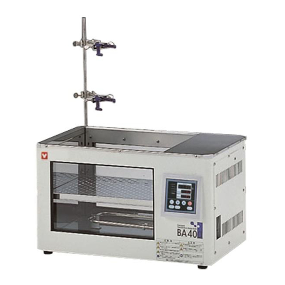
Page 10: Component Names And Functions
3. COMPONENT NAMES AND FUNCTIONS Main Unit Overview Rating badge Power cord のみ Power cord (BA300) Drainage hose... -
Page 11: Control Panel
3. COMPONENT NAMES AND FUNCTIONS Control Panel Panel Item Description START/STOP Key Press to start or stop an operation. Press repeatedly to increase or decrease setting value incrementally. Up/Down Arrow Keys Press and hold to increase or decrease setting value perpetually. ENTER Key Press to finalize setting. -
Page 12: Display Characters
3. COMPONENT NAMES AND FUNCTIONS Display Characters Character Identifier Description Purpose Signifies constant Appears while entering settings for temperature constant temperature operation. setting mode Appears while entering temperature Signifies temperature setting mode settings. Signifies auto stop and Appears while entering settings for quick auto stop setting AStP quick auto stop or auto stop mode. -
Page 13: Operation Procedures
4. OPERATION PROCEDURES Operation Modes Operation modes for this unit are defined in the table below: Name Description Page Pressing the FIXED TEMP key brings up constant temperature Constant Temperature setup mode. Mode (Continuous The "▲▼" keys are used to set temperature. Operation) Pressing the RUN/STOP key initiates or terminates operation. -
Page 14: Operation Functions
4. OPERATION PROCEDURES Operation Functions Operation functions for this unit are defined in the table below: № Name Description Page Auto This function is set to automatically activate (auto reset) overheat when chamber temperature exceeds the temperature prevention setting by 6°C. Although this device uses the same power source, display, and keypad as the control panel, it has an Overheat... -
Page 15: Mode & Function Flow
4. OPERATION PROCEDURES Mode & Function Flow The following chart illustrates mode and function flow for BA series units. -
Page 16: Overheat Prevention Device Setup
4. OPERATION PROCEDURES Overheat Prevention Device Setup This unit features an overheat prevention device (manual reset) which, has an independent temperature monitoring circuit, CPU, sensor and output circuit, but uses the same power source, display, and keys as the control panel. This is in addition to the internal automatic overheat prevention function (auto reset), built in for added measure against overheating. -
Page 17: Constant (Fixed) Temperature Mode
4. OPERATION PROCEDURES Constant (fixed) Temperature Mode 1. Turn on the main power switch (ELB) Constant Default values are displayed for about four seconds after turning temperature on power. Initial settings will then show in respective displays. operation procedure Temperature monitoring display: Shows current temperature in the chamber and other setting information. -
Page 18: Constant Temperature + Quick Auto Stop Mode
4. OPERATION PROCEDURES Constant Temperature + Quick Auto Stop Mode This mode is used to specify when unit should terminate constant temperature operation. This mode is set during operation only. Quick auto stop operation procedure 1. Set timer during constant temperature operation Confirm that unit is operating by confirming that FIXED TEMP lamp is illuminated. -
Page 19: Auto Stop Mode
4. OPERATION PROCEDURES Auto Stop Mode This mode is used to specify when unit should terminate constant temperature operation. In contrast to quick auto stop mode, this Auto stop operation mode must be set before operation. procedure 1. Set stop time ①... - Page 20 4. OPERATION PROCEDURES Auto Stop Mode To stop/terminate auto stop operation manually Operation stops automatically when timer reaches 0.00. An accompanying alarm sounds for approximately five seconds after operation terminates. Center display shows , indicating end of operation, with AUTO STOP lamps illuminated. Press the START/STOP key at any time during operation or after operation ends, to terminate auto stop operation mode.
-
Page 21: Auto Start Mode
4. OPERATION PROCEDURES Auto Start Mode This mode is used to specify an automatic start time for constant temperature operation. Auto start operation procedure 1. Set start time ① Press the TIMER key from the initial settings screen. ② Previous operation mode is displayed in center display. Press the TIMER key again and center display begins flashing. - Page 22 4. OPERATION PROCEDURES Auto Start Mode To terminate auto start operation Operation begins automatically when timer reaches 0.00; but must be stopped manually. Auto start mode can be cancelled any time before or during operation by pressing the START/STOP key for about one second.
-
Page 23: Programmed Operation
4. OPERATION PROCEDURES Programmed Operation This operation is used to run a combination of temperatures, times and modes as one operation. Programmed operation Temp Start Stop Time A maximum of six program pattern types can be entered (middle column). Program types ―... - Page 24 4. OPERATION PROCEDURES Programmed Operation Temperature rise and fall times for BA models are shown below in Temperature 10C increments. Numeric values signify time needed (in minutes) for temperature to fall/rise times for rise or fall for every 10C. Temperature stabilization time is an added BA models factor and not included in the table below.
- Page 25 4. OPERATION PROCEDURES Programmed Operation Building Programs The program pattern below will be used as an example for building programs: 1. Turn on main power switch (ELB ON “|”) Initial values will be shown for about 4 seconds after power-on, then displays will switch to the initial settings screen, showing current...
-
Page 26: Building Programs
4. OPERATION PROCEDURES Building Programs ① Select mode and press the ENTER key. ・When PrG1 is selected, the top display will show ・When PrG2 is selected, the top display will show , signifying program “pattern”. For PrG2 pattern, select either "1" or "2" (signifying the 2 available patterns) using the ▲▼... - Page 27 4. OPERATION PROCEDURES Building Programs ⑨ Press the ENTER key. , indicating timer setting for step 1, will be shown in the top display. Current timer setting will also be shown flashing in the center display. Before setting the timer, be sure to confirm temperature unit rise/fall capability.
- Page 28 4. OPERATION PROCEDURES Building Programs 6. End programmed operation An alert will sound when program ends. Top display will show "END", indicating that program has finished. Press the START/STOP key to return to initial setting screen. Timer function: Maximum setting for timer is 999 hours and 50 minutes. Timer can be set in increments of one minute, under 99 hours and 59 minutes.
- Page 29 Display will return to previous screen, where editing can be done. Note: Editing and confirmation must be done in the program setting screen. Contact a local dealer or Yamato sales office, if further questions arise concerning operation procedures.
-
Page 30: Program Planning Worksheet
4. OPERATION PROCEDURES Program Planning Worksheet Input into: PrG1 PrG2 PrG3 PAt1 PAt2 PAt3 Date Project Name Programmer Program Pattern... - Page 31 4. OPERATION PROCEDURES Program Planning Worksheet PrG1 PrG2 PrG3 PAt1 PAt2 PAt3 Input into: Date Project Name Programmer Input Value Repeat Function (Point of return:number of Temperature (℃) Time (min.) times) : : Step 1 : : Step 2 : :...
-
Page 32: Calibration Offset Function
4. OPERATION PROCEDURES Calibration Offset Function Calibration offset is function which can correct for any differences discovered between actual chamber temperature (taken manually) and Using calibration the temperature displayed on the control panel (taken by built-in offset sensor). Offset function can correct to either the positive or negative side of the entire unit temperature range. -
Page 33: Keypad Lock Function
4. OPERATION PROCEDURES Keypad Lock Function This function locks all keys except the SUBMENU and START/STOP keys, so that settings cannot be unintentionally changed. Using keypad lock Lock is set or cancelled with the SUBMENU key. ① Press the SUBMENU key. Select , indicating key lock function, using the ▲▼, and press the ENTER key. -
Page 34: Handling Precautions
If unit begins emitting smoke or abnormal odors for reasons unknown, turn off main power (ELB) immediately, disconnect power cable from power supply, and contact a local dealer or Yamato sales office for assistance. Continuing to operate without addressing abnormalities may cause fire or electric shock, resulting in serious injury or death. - Page 35 5. HANDLING PRECAUTIONS CAUTION! 8. Unattended operation If unit is to be left unattended for continuous operation, be sure to equip BA unit with a proper auto water supply device (such as a Level Controller [Model OBF10] product code: 221570) so that it will not be allowed to run dry.
-
Page 36: Maintenance Procedures
In order to be able to operate BA unit continually and without interruption, replacing hoses at least once every 2 years is recommended. Please contact Yamato Scientific regarding proper hose replacement. For further questions or assistance, please contact your local Yamato dealer or customer service center. -
Page 37: Storage And Disposal
Dispose of or recycle this unit in a responsible and environmentally friendly manner. Yamato Scientific Co., Ltd. strongly recommends disassembling unit, as far as is possible, in order to separate parts and recycle them in contribution to preserving the global environment. -
Page 38: Error Codes
Possible causes and countermeasures Temperature sensor interrupted, Sensor error Alarm lamp on detected disconnected or other malfunction Contact a local dealer or Yamato sales in display office Short circuit in SSR (solid state relay) Short circuit Alarm lamp on... -
Page 39: Troubleshooting
9. TROUBLESHOOTING Troubleshooting Guide Symptom Check Unit does not turn on/nothing is Whether power cable is connected securely to power terminal or displayed control panel outlet. displays when power switch Whether a power outage is in progress. (ELB) is turned “ON”. ... -
Page 40: Service And Repair
Requests for Repair When a problem occurs, terminate operation immediately, turn off main power switch (ELB) and disconnect power cable. Contact a local dealer or Yamato sales office for assistance. The following information is required for all repairs. ● Model name Refer to serial no. -
Page 41: Specifications
11. SPECIFICATIONS BA300 BA400 BA500 BA610 BA710 Operating temperature Ambient temp + 5 to 80℃ range Temperature ±0.02~±0.07℃ control accuracy Temperature ±0.1℃ distribution accuracy Time required to reach Approx. Approx. Approx. Approx. Approx. maximum temperature 120min. 110min. 165min. 160min. 200min. -
Page 42: Wiring Diagrams
12. WIRING DIAGRAMS All Models 220V Symbol Part name Earth leakage breaker T1, T2 Terminal blocks Motherboard PIO 1 Display circuit board Relay Current transformer Solid state relay Heater Double sensor Circulation pump... -
Page 43: Replacement Parts List
13. REPLACEMENT PARTS LIST All models Part Name Part No. Specification Manufacturer K-thermocouple Double sensor 1160030047 Yamato Scientific φ4.8L×125L PT1/8 VS model thermoregulator VS-4 (program), PIO, PLANAR, 1020000053 Yamato Scientific motherboard & display board two ribbon cables Current transformer cell... -
Page 44: List Of Hazardous Substances
14. LIST OF HAZARDOUS SUBSTANCES Never attempt to process explosives, flammables or any items which contain explosives or flammables 1) Nitroglycol, Glycerine trinitrate, Cellulose Nitrate and other explosive nitrate esters 2) Trinitrobenzen, Trinitrotoluene, Picric Acid and other explosive nitro compounds 3) Acetyl Hydroperoxide, Methyl Ethyl Ketone Peroxide, Benzoyl Peroxide and other organic peroxides 4) Metallic Azide, including Sodium Azide, etc. - Page 45 Always operate equipment in strict compliance to the handling and operation procedures set forth by this instruction manual. Yamato Scientific Co., Ltd. assumes no responsibility for malfunction, damage, injury or death, resulting from negligent equipment use. Never attempt to disassemble, repair or perform any procedure on BA series units which are not expressly mandated by this manual.
Need help?
Do you have a question about the BA300 and is the answer not in the manual?
Questions and answers