Advertisement
Quick Links
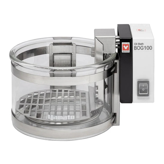
Glass Oil Bath
BOG 100/100T/200/200T series
Stainless Steel Oil Bath
BOS 100/100T/200/200T serie
Instruction Manual
⚫ Thank you for choosing BOG/BOS series Oil
Baths from Yamato Scientific Co., Ltd.
⚫ For proper equipment operation, please read
and become thoroughly familiar with this
instruction manual before use. Always keep
equipment documentation safe and close at
hand for convenient future reference.
Warning
Yamato Scientific Co., Ltd.
Second Edition
:
Read instruction manual
warnings and cautions carefully
and completely before
proceeding.
Printed on recycled paper
Advertisement

Related Manuals for Yamato BOG 100 Series


Summary of Contents for Yamato BOG 100 Series
- Page 1 BOS 100/100T/200/200T serie Instruction Manual Second Edition ⚫ Thank you for choosing BOG/BOS series Oil Baths from Yamato Scientific Co., Ltd. ⚫ For proper equipment operation, please read and become thoroughly familiar with this instruction manual before use. Always keep equipment documentation safe and close at hand for convenient future reference.
- Page 3 INTRODUCTION ⚫ Note that this product has a model for each destination, and product specifications and available options may differ. This product has models for each destination, and product specifications and available options may vary. Contact information differs for each destination. See P.73 ⚫...
- Page 4 TABLE OF CONTENTS TABLE OF CONTENTS ........................4 1. SAFETY PRECAUTIONS ......................1 Explanation of Symbols ......................1 Symbol Glossary ........................2 Warnings and Cautions ......................3 Residual Risk Map ........................5 List of Residual Risks ....................... 6 List of Residual Risks ....................... 7 2.
- Page 5 Warnings and Cautions ......................46 7. MAINTENANCE PROCEDURES ....................48 Precautions before Inspection ....................48 Precautions in Daily Maintenance ..................48 8. EXTENDED STORAGE AND DISPOSA ................... 49 Extended Storage ........................49 Disposal ..........................49 Disposal Considerations......................49 9. TROUBLESHOOTING ......................50 Reading Error Codes ......................
- Page 6 1. SAFETY PRECAUTIONS Explanation of Symbols...
- Page 7 1. SAFETY PRECAUTIONS Symbol Glossary WARNING / CAUTION Danger! Danger! Danger! Danger! General High Voltage Extremely Hot Moving Parts Blast Hazard Caution: Caution: Caution: Caution: Caution: Do Not Heat Water Only Shock Hazard! Burn Hazard! May Leak Water! Without Water! Caution: Toxic Chemicals RESTRICTION...
- Page 8 1. SAFETY PRECAUTIONS Warnings and Cautions WARNING Install in a location free of flammables and explosives. Never install or operate unit in a flammable or explosive gas atmosphere. Unit is NOT fire or blast resistant. Simply switching the Power switch "ON (|)" or "OFF (o)" can produce a spark, which can then be relayed during operation, causing fire or explosion when near flammable or explosive fluids, chemicals or gases/fumes.
- Page 9 1. SAFETY PRECAUTIONS Warnings and Cautions Handle power cable with care. ・ Do not operate unit with power cable bundled or tangled. Operating unit with power cable bundled or otherwise tangled, may cause power cable to overheat and catch fire. ・...
- Page 10 1. SAFETY PRECAUTIONS Residual Risk Map These figures indicate positions of caution labels. The numbers shown in the figure indicate the numbers listed in the "List of Residual Risks" in this manual. For details of individual residual risks, see the List of Residual Risks. Caution label - HOT 22,27,32 Caution/Rating label...
- Page 11 1. SAFETY PRECAUTIONS List of Residual Risks List of residual risks (instructions for risk avoidance) This list summarizes residual risks to avoid personal injuries or damages to properties during or related to the use of equipment. Be sure to fully understand or receive instructions on how to use, maintain and inspect equipment before starting operation.
- Page 12 1. SAFETY PRECAUTIONS List of Residual Risks Daily inspection/maintenance Degree of Risk Relevant Protective measures taken by the user risks description page Fire/ Be sure to disconnect power cable before WARNING P.48 Electric shock conducting inspection and maintenance. Clean off any oil on or around heater unit and Fire/ WARNING controller, to prevent short circuit or electric...
- Page 13 2. COMPONENT NAMES AND FUNCTIONS Overview External view Relay cable Controller unit (Single controller) Heater unit Bath reservoir Controller unit (Triple controller)
- Page 14 2. COMPONENT NAMES AND FUNCTIONS Bath/Heater Unit External view Heater guard Heater unit Power switch Fixing band Bath reservoir Independent overheat prevention device (IOPD) reset switch Relay cable Arbor Power cable Arbor Heater Heater guard * Figure shown above is a BOG unit...
- Page 15 2. COMPONENT NAMES AND FUNCTIONS Controller Unit (Single Controller) External view Main display Sub display 示部 LED lamps Up & Down keys ー Set key Run/Stop key Relay cable connection port External temperature sensor connection port...
- Page 16 2. COMPONENT NAMES AND FUNCTIONS Controller Unit (Triple Controller) External view Main display Sub display Primary Auxiliary 1 Auxiliary 2 Up & Down keys Set key Run/Stop key LED lamps Primary Auxiliary 1 Auxiliary 2 Relay cable connection port External temperature sensor connection port...
- Page 17 2. COMPONENT NAMES AND FUNCTIONS Components BOG100 Heater unit Heater unit Bath reservoir Bath reservoir Heater guard Heater guard Power switch Heater Heater BOG200 Heater unit Heater unit Bath reservoir Bath reservoir IOPD sensor Heater guard Heater guard Power switch Heater IOPD sensor Heater...
- Page 18 2. COMPONENT NAMES AND FUNCTIONS Components BOS100 Heater unit Heater unit Bath reservoir Bath reservoir Heater guard Heater guard Heater IOPD sensor Power switch Heater BOS200 Heater unit Heater unit Bath reservoir Bath reservoir Heater guard Heater guard Heater IOPD sensor Heater Power switch...
- Page 19 2. COMPONENT NAMES AND FUNCTIONS Accessories Check before operation that all the accessories are complete. Contact original dealer of purchase if anything is missing. Heater guard Arbor Stirrer bar Connector cap Identification sticker sheet Cable tie with tag Instruction manual Warranty card...
- Page 20 2. COMPONENT NAMES AND FUNCTIONS Control Panel ① ③ ⑤ ⑥ ② ⑦ ⑧ ⑨ ④ ⑩ Panel item Description Shows current bath fluid temperature, setting characters Main display ① and error codes Sub display Shows temperature setting and parameters. ②...
- Page 21 2. COMPONENT NAMES AND FUNCTIONS Display Characters All characters displayed when making settings and during operation are defined as follows: Character Letters Description Appears while entering offset temperature values. See "Calibration Offset" (P.33) Appears when setting Auto-resume function. See "Auto-resume Function" (P.34) Appears when enabling/disabling External temperature sensor.
- Page 22 3. PRE-OPERATION PROCEDURES Installation Precautions Choose an appropriate installation site. DO NOT install unit: ・ where installation surface is not completely level, not even or not clean. ・ where flammable or corrosive gases/fumes may be present ・ where external temperature will exceed 35°C, will fall below 5°C or will fluctuate largely. ・...
- Page 23 3. PRE-OPERATION PROCEDURES Installation Precautions Install in a dry location. Install unit where it will be free from liquid spray and other moisture. Failure to do so may result in control mechanisms becoming wet, causing malfunction, electric shock and/or fire. Take appropriate safety measures when installing equipment.
- Page 24 3. PRE-OPERATION PROCEDURES Installation Precautions Handle relay cable with care. Operating unit with relay cable bundled or otherwise tangled, may cause relay cable to overheat and catch fire. Do not modify, bend, forcibly twist or pull on relay cable. Doing so may cause unit to tip over, fire and/or electric shock.
- Page 25 4. PRE-OPERATIVE PREPARATIONS Mode & Function Flow Single controller...
- Page 26 4. PRE-OPERATIVE PREPARATIONS Mode & Function Flow Triple controller (Primary) Continued on the following page...
- Page 27 4. PRE-OPERATIVE PREPARATIONS Mode & Function Flow Triple controller (Primary) Continued from the previous page...
- Page 28 4. PRE-OPERATIVE PREPARATIONS Mode & Function Flow Triple controller (Auxiliary)
- Page 29 4. PRE-OPERATIVE PREPARATIONS Safety Functions Safety functions for this unit are defined in the table below № Name Description ① Independent overheat prevention device (IOPD) DO NOT heat without adding required amount of silicone oil. Unit is equipped with independent overheat prevention device (IOPD) for accidental overheating.
- Page 30 4. PRE-OPERATIVE PREPARATIONS Safety Functions ② Automatic overheat prevention function In addition to IOPD, unit has automatic overheat prevention function (auto reset) built in the controller for redundant safety measures. When bath fluid temperature exceeds objective temperature setting by 12 °C, power supply to heater circuit is shut off.
- Page 31 4. PRE-OPERATIVE PREPARATIONS Operation Preparations Operation precautions ・ Exercise caution in regard to the following. ・ Use ONLY silicon oil for bath fluid. Using any fluids other than silicone oil may impair safety functions, causing injury or burns. ・ Check installation site and environmental conditions, and ensure that there is no damage on bath reservoir.
- Page 32 4. PRE-OPERATIVE PREPARATIONS Operation Preparations Supply of silicone oil * Keep fluid level no lower than bottommost slit in heater guard. Insufficient fluid level may result in inaccurate or erratic temperature readings or inability to control temperature, which may cause overheating and fire hazards. (where the oil is at 23 °C and no containers are set in the bath) Minimum level (where oil temperature is at 23 °C)
- Page 33 4. PRE-OPERATIVE PREPARATIONS Operation Preparations Heater guard Be sure to attach heater guard whenever operating unit. Direct contact between sample and heater may cause damage to heater, leading to serious hazards or mishaps. Ensure that heater guard covers rising part of heater, and that capillary of overheat prevention sensor passes through the notch in heater guard.
- Page 34 4. PRE-OPERATIVE PREPARATIONS Identification Sticker Identification stickers are provided for multiple units operation. With these stickers each unit and controller can be visually distinguished. Apply cable ties with tag, and stickers to the positions that are easy to see. Heater unit is preferable to bath reservoir for affixing the stickers, or oil mist will peel stickers off within a short time.
- Page 35 5. OPERATION PROCEDURES Operation Procedure 1. Turn power on Turn ON (|) the Power switch located on heater unit. Main display : Shows temperature reading following the software version "V.*.*" Sub display : Temperature reading will show 2. Set temperature ①...
- Page 36 5. OPERATION PROCEDURES User Setting List of user setting items • Press and hold for three seconds to show user setting. Select an item by using ∧∨ keys. Press again to edit the displayed item. • While the user setting item is displayed, leaving unit without key operation for about two minutes will discard the unconfirmed changes, and display reverts to the standard operation screen.
- Page 37 5. OPERATION PROCEDURES User Setting List of user setting items • Following setting items will appear when External temperature sensor is enabled • Calibration offset “CA2” can be set or altered during operation. Panel item Description Page This function can correct for any differences discovered between actual temperature of the object under heating, and the temperature displayed on the control panel.
- Page 38 5. OPERATION PROCEDURES Calibration Offset Calibration offset function is to compensate for differences in temperature reading (as taken by unit sensor) and actual temperature of silicone oil (as taken manually). Unit can be offset to either the positive or negative side of temperature line for entire temperature range of unit ・Run unit at desired temperature.
- Page 39 5. OPERATION PROCEDURES Auto-resume Function Select recovery mode for the event of a power failure. “on”: Unit automatically reverts to status just before power loss and begin operation once again from that point. “oFF”: Unit goes into idle at power recovery. Setting parameters: on or oFF (default setting is "oFF") With this function set to “on”, there is a possibility that unit unexpectedly begins operation.
- Page 40 5. OPERATION PROCEDURES External Temperature Sensor Setting Enabling/disabling External temperature sensor “on”: Enabled “oFF”: Disabled Setting parameters: on or oFF (default setting is "oFF") When set to “on”, temperature readout will be switched to that of External temperature sensor. Putting the sensor in the object to be heated allows unit to control temperature based on temperature of the heated object.
- Page 41 5. OPERATION PROCEDURES LED Brightness Setting Change the LED brightness of the control panel. The brightness can be set in 8 levels from 0 to 7. (Default setting is "4") * Settings cannot be changed during operation. 1 Enter user setting Press and hold for three seconds in standard operation screen.
- Page 42 5. OPERATION PROCEDURES Calibration Offset for External Temperature Sensor * This function is displayed in the user setting only when External temperature sensor is enabled. This function can correct any differences discovered between actual temperature of the object under heating (taken manually) and the temperature displayed on the control panel (taken by External temperature sensor).
- Page 43 5. OPERATION PROCEDURES Bath Fluid Temperature Readout * This function is displayed in the user setting only when External temperature sensor is enabled. Check bath fluid temperature while External temperature sensor is enabled. Main display shows temperature of the object under heating, taken by External temperature sensor. To see temperature of silicone oil in the bath, follow the steps below.
- Page 44 5. OPERATION PROCEDURES Three-unit Interlock Function (Triple controller) BOG/BOS units can operate simultaneously up to three units by Interlock function. ・ Primary unit + 2 Auxiliary units ・ Primary unit + 1 Auxiliary unit + 1 Independent unit (see P.40 for details) While linked, auxiliary units cannot individually start operation or change temperature setting.
- Page 45 5. OPERATION PROCEDURES 運転のしかた Interlock Function (Triple Controller) ・Use Interlock function (Primary) Turn on (Enable) or off (disable) the function, select the number of devices to be linked, and set temperature difference for automatic temperature setting. When selecting “1” for the number of Auxiliary units, Auxiliary 1 will be linked, and Auxiliary 2 will be independent.
- Page 46 5. OPERATION PROCEDURES Interlock Function (Triple Controller) 4 Change temperature differential setting ①Use the ∧∨ keys to alter the setting. Main display: Alternately shows “tEP” and temperature setting for Primary Sub display: Current set value flashes ② Press to finalize. After completion, proceed to next setting 5 Start interlocked operation Press and hold...
- Page 47 5. OPERATION PROCEDURES Interlock Function (Triple Controller) Quick start/stop of Interlock function In standard operation screen, holding down the ∧ key for three seconds can start/stop interlocked operation. Current setting is reflected for the number of units and temperature setting. Press &...
- Page 48 5. OPERATION PROCEDURES Interlock Function (Triple Controller) ・Use Interlock function (Auxiliary) Enable/disable the function When disabled, a link request from Primary is ignored. Disabling the function in linked state cancels the linkage thereof. Setting parameters: on or oFF (default setting is “on”) * Settings cannot be changed during operation.
- Page 49 5. OPERATION PROCEDURES Temperature Differential Setting (Triple controller) Enter temperature differential value. Set temperature differentials for batch setting in linked state. Setting range: -100 to +100 °C (default setting is “10”) * Can be set only by Primary unit * Setting change can also be made during operation. * Added to user setting menu while units are linked.
- Page 50 5. OPERATION PROCEDURES Auto-resume Function (Triple Controller) Select recovery mode for the event of a power failure. “on”: Unit automatically reverts to status just before power loss and begin operation once again from that point. “oFF”: Unit goes into idle at power recovery. “Lin”: Units remain linked in standby state.
- Page 51 6. HANDLING PRECAUTIONS Warnings and Cautions WARNING DO NOT use explosive or flammable fluid as heating medium. Never attempt to use explosives, flammables or any items which contain explosives or flammables. Fire or explosion may result. See "LIST OF HAZARDOUS SUBSTANCES" (P.70) Use TSF428-100 or its equivalent silicone oils.
- Page 52 6. HANDLING PRECAUTIONS Warnings and Cautions CAUTION ALWAYS wear protective equipment Prepare safety gear for hazardous substances whenever operating this unit to avoid injury or burns. ALWAYS run equipment within specified temperature range The temperature control range is RT +5 °C to 240 °C (BOG100-A/200-A), and RT +5 °C to 250 °C (BOS100-A/200-A).
- Page 53 7. MAINTENANCE PROCEDURES Precautions before Inspection WARNING ⚫ Be sure to disconnect power cable before conducting inspection and maintenance. Clean off any oil on or around heater unit and controller, to prevent electrical leakage and/or fire. ⚫ ⚫ Perform inspections and maintenance when unit and bath fluid are at room temperature. ⚫...
- Page 54 Dispose of this unit in accordance with local laws and regulations. Dispose of or recycle this unit in a responsible and environmentally friendly manner. Yamato Scientific Co., Ltd. strongly recommends disassembling unit, as far as is possible, in order to separate parts and recycle them in contribution to preserving the global environment. Major...
- Page 55 9. TROUBLESHOOTING Reading Error Codes When an operational error or malfunction occurs, unit shuts off heater and Error lamp illuminates. Error codes will show flashing in main display. Confirm code and turn off the Power switch immediately, then block access to unit. Error Codes Description Possible causes and measures...
- Page 56 9. TROUBLESHOOTING Reading Error Codes Unit detects following abnormalities only when External temperature sensor is enabled Error codes will show flashing in main display. Confirm code and turn off the Power switch immediately, and check the solutions below. Error Codes Description Possible causes and measures ⚫...
- Page 57 9. TROUBLESHOOTING Reading Error Codes Unit detects following abnormalities only when units are linked by Triple controller. Error codes will show flashing in main display. Confirm code and check the settings. * The error “E00“ will be automatically released as soon as the cause is eliminated when “FAL” is not shown in display.
- Page 58 9. TROUBLESHOOTING Troubleshooting Guide Symptom Check ・ Whether power cable is connected securely to power outlet ・ Whether a power outage is in progress Display is blank when the Power switch is ・ Whether IOPD reset switch is not pressed after its turned ON (|).
- Page 59 10. SERVICE & REPAIR Requests for Repair Requests for Repair If abnormalities remain after confirming "Troubleshooting Guide", terminate operation, turn OFF (○) the Power switch, and disconnect power cable. Contact original dealer of purchase for assistance. The following information is required for all repairs. ⚫...
- Page 60 11. SPECIFICATIONS Specifications(BOG100 Series) Product Name Glass Oil Bath Model BOG100 BOG100-Y BOG110-B BOG110-Y 5~35 °C Operating ambient temperature range Temperature setting 0~260 °C range Temperature control RT +5 to 240 °C *2,3 range Temperature control ±0.3 °C (at 200 °C, stirring) accuracy Exterior Chromium-free electrogalvanized steel sheet, baked-on finish...
- Page 61 11. SPECIFICATIONS Specifications(BOG200 Series) Product Name Glass Oil Bath Model BOG200 BOG200-Y BOG210-B BOG210-Y Operating ambient temperature 5~35 °C range Temperature setting 0~260 °C range Temperature control RT +5 to 240 °C *2,3 range Temperature control ±0.3 °C (at 200 °C, stirring) accuracy Exterior Chromium-free electrogalvanized steel sheet, baked-on finish...
- Page 62 11. SPECIFICATIONS Specifications(BOS100 Series) Product Name Stainless Steel Oil Bath Model BOS100 BOS100-Y BOS110-B BOS110-Y Operating ambient temperature 5~35 °C range Temperature setting 0~260 °C range Temperature control RT +5 to 250 °C *2 range Temperature control ±0.3 °C (at 200 °C, stirring) accuracy Exterior Chromium-free electrogalvanized steel sheet, baked-on finish...
- Page 63 11. SPECIFICATIONS Specifications(BOS200 Series) Product Name Stainless Steel Oil Bath Model BOS200 BOS200-Y BOS210-B BOS210-Y Operating ambient temperature 5~35 °C range Temperature setting 0~260 °C range Temperature control RT +5 to 250 °C *2 range Temperature control ±0.3 °C (at 200 °C, stirring) accuracy Exterior Chromium-free electrogalvanized steel sheet, baked-on finish...
- Page 64 11. SPECIFICATIONS Specifications(BOG100T Series) Product Name Glass Oil Bath Model BOG100T BOG100T-Y BOG110T-B BOG110T-Y 5~35 °C Operating ambient temperature range Temperature setting 0~260 °C range Temperature control RT +5 to 240 °C *2,3 range Temperature control ±0.3 °C (at 200 °C, stirring) accuracy Exterior Chromium-free electrogalvanized steel sheet, baked-on finish...
- Page 65 11. SPECIFICATIONS Specifications(BOG200T Series) Product Name Glass Oil Bath Model BOG200T BOG200T-Y BOG210T-B BOG210T-Y 5~35 °C Operating ambient temperature range Temperature setting 0~260 °C range Temperature control RT +5 to 240 °C *2,3 range Temperature control ±0.3 °C (at 200 °C, stirring) accuracy Exterior Chromium-free electrogalvanized steel sheet, baked-on finish...
- Page 66 11. SPECIFICATIONS Specifications(BOS100T Series) Product Name Glass Oil Bath Model BOG100T BOG100T-Y BOG110T-B BOG110T-Y 5~35 °C Operating ambient temperature range Temperature setting 0~260 °C range Temperature control RT +5 to 250 °C *2 ※1 range Temperature control ±0.3 °C (at 200 °C, stirring) accuracy Exterior Chromium-free electrogalvanized steel sheet, baked-on finish...
- Page 67 11. SPECIFICATIONS Specifications(BOS200T Series) Product Name Glass Oil Bath Model BOG200T BOG200T-Y BOG210T-B BOG210T-Y 5~35 °C Operating ambient temperature range Temperature setting 0~260 °C range Temperature control RT +5 to 250 °C *2 ※1 range Temperature control ±0.3 °C (at 200 °C, stirring) accuracy Exterior Chromium-free electrogalvanized steel sheet, baked-on finish...
- Page 68 12. OPTIONAL ACCESSORIES List of Options Product Name Product code Description Contents Temperature sensor (φ3 SST tube) External 222191 Pt100 (class A) 1 pc which can be directly placed in the temperature sensor object to be heated. With this sensor connected and enabled, unit can control temperature based on the temperature of the object under...
- Page 69 12. OPTIONAL ACCESSORIES List of Options Controller mounting hardware Install according to the following procedure. ① Remove four screws in the back of the controller. Remove screws ② Attach L-shaped mounting hardware with the removed screws as shown in the right figure. Fasten screws Controller mounting hardware can be attached at every 90 degrees.
- Page 70 13. REFERENCE DATA Temperature Rise Curve BOG100/200 Temperature setting: 240 °C Ambient temperature: 23 °C Power supply (frequency): 100 V AC (50 Hz) Heating medium: silicone oil TSF458-100 Stirrer: magnetic stirrer Rotation speed: 250 rpm Stirrer bar: included PTFE stirrer bar Time (h:mm) BOS100/200 Temperature setting: 250 °C...
- Page 71 13. REFERENCE DATA Temperature Fall Curve BOG100/200 Ambient temperature: 23 °C Heating medium: silicone oil TSF458-100 Stirrer: magnetic stirrer Rotation speed: 250 rpm Stirrer bar: included PTFE stirrer bar Time (h:mm) BOS100/200 Ambient temperature: 23 °C Heating medium: silicone oil TSF458-100 Stirrer: magnetic stirrer Rotation speed: 250 rpm Stirrer bar: included PTFE stirrer bar...
- Page 72 13. REFERENCE DATA Step Chart BOG100 Temperature setting: 80 → 140 → 200 → 240 °C Ambient temperature: 23 °C Power supply (frequency): 100 V AC (50 Hz) Heating medium: silicone oil TSF458-100 Stirrer: magnetic stirrer Rotation speed: 250 rpm Stirrer bar: included PTFE stirrer bar Time (h:mm) BOG200...
- Page 73 13. REFERENCE DATA Step Chart BOS100 Temperature setting: 80 → 140 → 200 → 250 °C Ambient temperature: 23 °C Power supply (frequency): 100 V AC (50 Hz) Heating medium: silicone oil TSF458-100 Stirrer: magnetic stirrer Rotation speed: 250 rpm Stirrer bar: included PTFE stirrer bar Time (h:mm) BOS200...
- Page 74 13. REFERENCE DATA Temperature Rise Curve (with External Temperature Sensor Enabled) BOG200 Temperature setting: 180 °C Ambient temperature: 23 °C Power supply (frequency): 100 V AC (50 Hz) Object to be heated: Ethylene glycol 500 ml (99% concentration) External temperature sensor: Pt100 (class A) Heating medium: silicone oil TSF458-100 Stirrer: magnetic stirrer Rotation speed: 250 rpm...
- Page 75 14. WIRING DIAGRAM Wiring Diagram All models * ----- indicates optional components Wiring Diagram Symbol Glossary Symbol Component Symbol Component Power switch F1, F2 Fuse Independent overheat prevention Heater device SSR1 Heater control relay MAIN1 CPU board Temperature sensor DISP1 Display board Options Symbol...
- Page 76 15. LIST OF HAZARDOUS SUBSTANCES Never directly pour and heat explosives, flammables or any items which contain explosives or flammables in the bath reservoir. Exercise extreme caution when heating these substances using glassware immersing in silicone oil, and it must be done under strict supervision and control.
- Page 77 16. STANDARD INSTALLATION MANUAL Install this equipment according to following format (check options and special specifications separately). Charged Personnel or Installation proved Model Serial Number Installation Date Company Name for Judgment Installation Chapter No. & Reference page of № Item Implementation method Judgment instruction manual...
- Page 78 Inquiry from a mobile phone: 0570-064-525 FAX:055-284-5210 Reception hours: 9:00-17:30. (Service also available for 12:00-13:00) http://www.yamato-net.co.jp 2)USA・Canada・Latin America Yamato Scientific America Inc. 925 Walsh Avenue, Santa Clara,CA 95050, U.S.A http://www.yamato-usa.com Toll Free: 1-800-2-YAMATO (1-800-292-6286) 3)Other Country For repair service, maintenance service and consumables purchase support, please contact to our distributors from whom you purchased.
- Page 79 Notice ● Instruction manual descriptions and specifications are subject to change without notice. ● Yamato Scientific Co., Ltd. will replace flawed instruction manuals (pages missing, pages out of order, etc.) upon request. Instruction Manual Glass Oil Bath...
Need help?
Do you have a question about the BOG 100 Series and is the answer not in the manual?
Questions and answers