Table of Contents
Advertisement
Quick Links
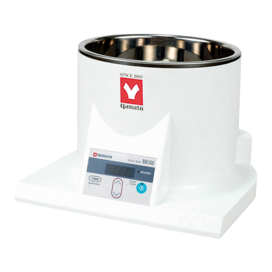
Water Bath
BM500/510
Oil Bath
BO400/410
Instruction Manual
-
Fourth
Thank you for purchasing "Water Bath, BM / Oil
Bath, BO Series" of Yamato Scientific Co., Ltd.
To use this unit properly, read this "Instruction
Manual" thoroughly before using this unit.
Keep this instruction manual around this unit for
referring at anytime.
WARNING!:
Carefully read and thoroughly understand the
important warning items described in this
manual before using this unit.
Yamato Scientific Co. LTD.,
Edition -
This paper has been printed on recycled paper.
Advertisement
Table of Contents

Related Manuals for Yamato BM500


Summary of Contents for Yamato BM500
- Page 1 Fourth Edition - Thank you for purchasing "Water Bath, BM / Oil Bath, BO Series" of Yamato Scientific Co., Ltd. To use this unit properly, read this "Instruction Manual" thoroughly before using this unit. Keep this instruction manual around this unit for referring at anytime.
-
Page 2: Table Of Contents
Contents 1.Cautions in Using with Safety............. 1 • Explanation........................1 • Table of Illustrated Symbols ..................2 • Fundamental Matters of "WARNING!" and "CAUTION!" ..........3 2.Before Using This Unit................. 5 • Requirements for Installation..................5 • Installation Method ......................8 •... -
Page 3: Cautions In Using With Safety
1.Cautions in Using with Safety Explanation MEANING OF ILLUSTRATED SYMBOLS Illustrated Symbols Various symbols are used in this safety manual in order to use the unit without danger of injury and damage of the unit. A list of problems caused by ignoring the warnings and improper handling is divided as shown below.Be sure that you understand the warnings and cautions in this manual before operating the unit. -
Page 4: Table Of Illustrated Symbols
1.Cautions in Using with Safety Table of Illustrated Symbols Warning Warning, Warning, Warning, Warning, Warning, generally high voltage high temperature drive train explosive Caution Caution, Caution, Caution, Caution, Caution, generally electrical shock scald no road heating not to drench Caution, Caution, water only deadly poison... -
Page 5: Fundamental Matters Of "Warning!" And "Caution
1.Cautions in Using with Safety Fundamental Matters of "WARNING!" and "CAUTION!" WARNING! Do not use this unit in an area where there is flammable or explosive gas Never use this unit in an area where there is flammable or explosive gas. This unit is not explosion-proof. An arc may be generated when the power switch is turned on or off, and fire/explosion may result. - Page 6 During a thunder storm During a thunderstorm, turn off the power key immediately, then turn off the circuit breaker and the main power. If this procedure is not followed, fire or electrical shock may be caused. When electric power failure occurs… The device stops operation when electric power failure occurs.
-
Page 7: Before Using This Unit
• Do not connect the earth wire to the ground for telephone wire or lightning conductor. If not, fire disaster or electric shock may be caused. • Use the receptacle with exclusive earth terminal for the BM500 and B0400 models which ha large capacity with single-phase 100V to 120V specification. - Page 8 2.Before Using This Unit Requirements for Installation WARNING! 3. Do not use this unit in an area where there is flammable or explosive gas • Never use this unit in an area where there is flammable or explosive gas. This unit is not explosion-proof.
- Page 9 7. Choose a correct power distribution board or receptacle • Choose a correct power distribution board or receptacle that meets the unit’s rated electric capacity. BM500/BO400: 100 to 120V AC, 12.5A Electric capacity: BM510/BO410: 200 to 240V AC (single phase), 6.5A NOTE) There could be the case that the unit does not run even after turning ON the power.
-
Page 10: Installation Method
2.Before Using This Unit Installation Method 9. Handling of power code 1.Warning • Do not entangle the power cord. This will cause overheating and possibly a fire. • Do not bend or twist the power cord, or apply excessive tension to it. This may cause a fire and electrical shock. -
Page 11: Preparations For Operation
2.Before Using This Unit Preparations for Operation Precautions at operation for water bath BM500 and BM510 Be careful about the followings at the operation of device. ① Connect the power to the receptacle which has sufficient capacity left. ② Do not move the device during the operation. - Page 12 2.Before Using This Unit Preparations for Operation Fluid medium for oil bath BO400/BO410 The maximum operating temperature of BO400/410 model oil bath is 180℃. Select the silicon oil used only for heat transfer medium, with heat resistance and open system (heat-resistant dimethyl silicon oil) having the viscosity of 50 ㎜...
- Page 13 2.Before Using This Unit Preparations for Operation Water/oil supply for in-bath The in-bath installed on the main body is removable for easy supply of water/oil. Be careful about the followings when supplying water/oil. Water supply for BM model water bath •...
-
Page 14: Description And Function Of Each Part
3.Description and Function of Each Part Main Unit Front view Removable in-bath (SUS316) Outer covering Made by heat-resistant ABS resin Control panel Rear view Power switch (circuit breaker) Connector for power cord Exclusive connector for bath operational setting function in rotary evaporator on the RE600/800 model. -
Page 15: Control Panel
3.Description and Function of Each Part Control Panel ① ② ③ ⑦ ⑥ ⑧ ⑤ ④ Exclusive connector for bath operational setting function in rotary evaporator on the RE600/800 model. (The connecting cord is attached to the RE600/800 model.) LEAK LEAK VR600/800 Vacuum controller... -
Page 16: Characters Of The Controller
3.Description and Function of Each Part Characters of the Controller Indicated characters for BM/BO type controller are follows; Character Identifier Name Purpose The characters on the timer selection screen Selection/standby Selection screen for quick auto stop timer screen display for quick operation which stops the operation at preset time AStP auto stop/auto stop... -
Page 17: Operation Method
4.Operation Method Operation Mode and Function List The operation modes of this unit are as follows; Name Description Page Fixed Temperature Set the desired temperature with the △▽ keys. Press the Operation START/STOP key for one second to start operation. Press the same key again to stop operation. - Page 18 4.Operation Method Operation Mode and Function List The maintenance functions of device are described as follows. The maintenance mode shares the operation key with the timer function. Keep pressing the TIMER key for four seconds to go into the maintenance mode. Name Description Page...
-
Page 19: Operation Mode, Function Setting Key, And Characters
4.Operation Method Operation Mode, Function Setting Key, and Characters The following key operations and characters are used for the settings of operation mode and functions. -
Page 20: Fixed Temperature Operation
4.Operation Method Fixed Temperature Operation Fix Temperature Operation is regular drive mode for continuous driving. 1. Turn on the power switch (turn the breaker to ON) Fixed temperature • After the power switch on the back surface of main body is operation procedures turned to on, the screen displays the initial values for about four seconds. -
Page 21: Quick Auto Stop Operation
4.Operation Method Quick Auto Stop Operation Quick Auto Stop Operation is driving mode for adding auto stop timer during fix temperature operation. 1. Turn on the power switch (turn the breaker to ON) Quick auto stop • After the power switch on the back surface of main body is operation procedures turned to on, the screen displays the initial values for about four seconds. - Page 22 4.Operation Method Quick Auto Stop Operation 6. Stop operation • Press the START/STOP key for about one second. The device stops operation. The operation lamp lights off. The HEATER lamp lights off. The screen displays the current bath temperature. To correct the setting mistake or check the preset value… Press the △▽...
-
Page 23: Auto Stop Operation
4.Operation Method Auto Stop Operation Auto Stop Operation is driving mode for stop drive when to reach preset time. Set the Auto Stop Operation before driving. 1. Turn on the power switch (turn the breaker to ON) Auto stop • After the power switch on the back surface of main body is operation procedures turned to on, the screen displays the initial values for about four seconds. - Page 24 4.Operation Method Auto Stop Operation To correct the setting mistake or check the preset value… Press the △▽ key again to correct the setting mistake or to check the preset value. The screen changes to the preset temperature screen to display it. To change the preset temperature during operation…...
-
Page 25: Auto Start Operation
4.Operation Method Auto Start Operation Auto Start Operation is timer driving mode for start drive when to reach preset time. Set the Auto Start Operation before driving. 1. Turn on the power switch (turn the breaker to ON) Auto start •... - Page 26 4.Operation Method Auto Start Operation 5. Stop operation • Press the START/STOP key for about one second. The device stops operation. The operation lamp lights off. The HEATER lamp lights off. The screen displays the current bath temperature. To correct the setting mistake or check the preset value… Press the △▽...
-
Page 27: Setting Of Overheating Prevention Device
The safety device for overheating prevention also includes the automatic overheating prevention function (manual return) of controller. The device also contains a thermal fuse to set the operating temperature to 128℃(for BM500 and 510 models) or to 192℃(for BO400 and 410 models) for double safety function. -
Page 28: Key Lock Function
4.Operation Method Key Lock Function This function keylocks the operating state of device. Use the TIMER Use Keylock Function key to set or cancel the function. ① Press the TIMER key for about four seconds. Select the "LocK" which indicates operation keylock. ②... -
Page 29: Calibration Offset Function
4.Operation Method Calibration Offset Function The calibration offset function corrects the difference between the Use Calibration Offset temperature inside the bath actually measured using the thermometer Function or temperature recorder and the temperature controlled by the controller on the main body (temperature controller) to match them. Input a plus value by the difference when the temperature inside the bath is higher than the preset value. -
Page 30: Reparation Function At Power Failure
4.Operation Method Reparation Function at Power Failure This function selects the operating state of bath at recovery, after power failure. auto returning or stop status The setting at factory shipment is “OFF”. Press the TIMER key for about four seconds and then press it few times to select the "Pon". -
Page 31: Handling Precautions
5.Handling Precautions WARNING! 1. Substances that cannot be used Never use explosive substances, flammable substances and substances that include explosive or flammable ingredients in this unit. Explosion or fire may occur. (Refer to page 40 "List of Dangerous Substances".) 2. Do not perform unmanned operation For safety reason, do not perform unmanned operation of the devices that requires oil. - Page 32 CAUTION! 5. Applicable oil Use ion-exchange water or exchange water diligently for the BM model water bath to prevent the accumulation of boiling scale or calculus. Do not use the fluid other than specified silicon oil for the BO model oil bath. Use the specified silicon oil.
-
Page 33: Maintenance Method
6.Maintenance Method Daily Inspection and Maintenance For the safety use of this unit, please perform the daily inspection and maintenance without fail. WARNING! • Be sure to disconnect the power cord during inspection or maintenance of device. • Wipe water or oil on or around the operating panel and heater completely to prevent ground leakage and electric shock. -
Page 34: Long Storage And Disposal
7.Long storage and disposal When not using this unit for long term / When disposing CAUTION! When not using this unit for long term… • Turn off the power and disconnect the power cord. • Drain the oil/water inside the bath and wipe it completely. WARNING! When disposing…... -
Page 35: In The Event Of Failure
8.In the Event of Failure… Safety Device and Error Code The error messages displayed on the controller are as follows. The device stops heater output and notifies the users of abnormality by indicating the corresponding error code. Record the code and turn off the power, then call the service department of our company. Error Code Cause/Solution Disconnection/removal... -
Page 36: Trouble Shooting
In the case if the error other than listed above occurred, turn off the power switch and primary power source immediately. Contact the shop of your purchase or nearest Yamato Scientific Service Office. -
Page 37: After Service And Warranty
If the failure occurs, stop the operation, turn OFF the power switch, and unplug the power plug. Please contact the sales agency that this unit was purchased, or the Yamato Scientific's sales office. < Check following items before contact >... -
Page 38: Specification
10.Specification Product Name Water Bath Oil Bath Model BM500 BM510 BO400 BO410 Approx. 4 liters (Amount of water/oil filled at 30 mm from the upper edge of Bath capacity in-bath) Effective bath capacity Approx. 4 liters Bath material SUS316 Temperature control Room temp.+5℃~90℃... -
Page 39: Wiring Diagram
11.Wiring Diagram BM500/510 Symbol Part name Circuit protector Terminal block Heater Thermal fuse Solid state relay PLANAR PLANAR board K-thermocouple Display board Connector for bath signal Symbol Part name Circuit protector Terminal block Heater Thermal fuse Solid state relay PLANAR PLANAR board... - Page 40 11.Wiring Diagram BO400/410 Symbol Part name Circuit protector Terminal block Heater Thermal fuse Solid state relay PLANAR PLANAR board K-thermocouple Display board Connector for bath signal Symbol Part name Circuit protector Terminal block Heater Thermal fuse Solid state relay PLANAR PLANAR board K-thermocouple Display board Connector for bath signal...
-
Page 41: Replacement Parts Table
Display board LT00013603 BM/BO display board Yamato Scientific Sensor LT00026845 BM/BO K-thermocouple Yamato Scientific Pillar fitting LT00012102 Φ15×L20 M4 Yamato Scientific For BM500 Part Name Code No. Specification Manufacturer Thermal fuse LT00015311 Sakaguchi Dennetsu 128℃ E4A50128C Heater LT00028682 120V 1440W... -
Page 42: Reference
13.Reference List of Dangerous Substances Never use explosive substances, flammable substances and substances that include explosive or flammable ingredients in this unit. EXPLOSIVE Ethylene glycol dinitrate (nitro glycol), Glycerin trinitrate (nitroglycerine), Cellulose nitrate (nitrocellulose), and other explosive nitrate esters Trinitrobenzene, Trinitrotoluene, Trinitrophenol (picric acid), and other explosive EXPLOSIVE: nitro compounds Acetyl hidroperoxide (peracetic acid), Methyl ethyl ketone peroxide, Benzyl... -
Page 43: Installation Standard Manual
14.Installation Standard Manual * Install the unit according the procedure described below (check options and special specifications separately). Person in charge of installation Person in charge of Model Serial number Date Judgment (company name) installation № Item Method Reference operation manual Judgment Specifications Check the quantities of accessories with... - Page 44 Responsibility Please follow the instructions in this document when using this unit. Yamato Scientific has no responsibility for the accidents or breakdown of device if it is used with a failure to comply. Never conduct what this document forbids. Unexpected accidents or breakdown may result in.
Need help?
Do you have a question about the BM500 and is the answer not in the manual?
Questions and answers