Table of Contents
Advertisement
Quick Links
Advertisement
Table of Contents

Related Manuals for HMS Networks Anybus WirelessBolt RJ45 PoE Series


Summary of Contents for HMS Networks Anybus WirelessBolt RJ45 PoE Series
- Page 1 ® ™ Anybus Wireless Bolt RJ45 PoE STARTUP GUIDE SP2359 1.3 en-US ENGLISH...
-
Page 2: Important User Information
Important User Information Disclaimer The information in this document is for informational purposes only. Please inform HMS Industrial Networks of any inaccuracies or omissions found in this document. HMS Industrial Networks disclaims any responsibility or liability for any errors that may appear in this document. HMS Industrial Networks reserves the right to modify its products in line with its policy of continuous product development. -
Page 3: About This Document
Preparation 3 (16) Preparation About This Document This document describes how to install Anybus Wireless Bolt RJ45 PoE and set up a basic configuration. For additional documentation, configuration examples, FAQs, troubleshooting guides and technical support, please visit www.anybus.com/support. Document Conventions The following conventions are used to indicate safety information and other important content in this document: WARNING... -
Page 4: Intended Use
Preparation 4 (16) Intended Use This equipment is intended to provide wireless communication over WLAN and ® Bluetooth to wired networks. Typical applications for this equipment: • Adding wireless cloud connectivity to industrial devices • Accessing devices from a laptop, smartphone or tablet •... -
Page 5: Installation
Installation 5 (16) Installation General Safety Instructions Caution This equipment emits RF energy in the ISM (Industrial, Scientific, Medical) band. Make sure that all medical devices used in proximity to this device meet appropriate susceptibility specifications for this type of RF energy. This product is recommended for use in both industrial and domestic environments. -
Page 6: Mechanical Installation
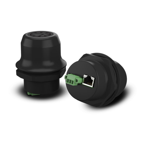
Installation 6 (16) Mechanical Installation The device is intended to be mounted on top of a machine or cabinet through an M50 (50.5 mm) hole using the included sealing ring and nut. The top mounting surface (in contact with the sealing) must be flat with a finish equivalent to Ra 3.2 or finer and cleaned and free from oils and greases. - Page 7 Installation 7 (16) Connectors Connecting power with reverse polarity or using the wrong type of power supply may damage the equipment. Make sure that the power supply is connected correctly and of the recommended type. See also Technical Data, p. 14 regarding power supply requirements.
-
Page 8: Rj45 Led Indicators
Installation 8 (16) RJ45 LED Indicators Function LED A – LINK/ACTIVITY No Ethernet link or no power Yellow Ethernet link established Yellow, flashing Ethernet traffic LED B – STATUS Function No power Blue Connected on all configured wireless interfaces Purple Trying to connect to WLAN/Bluetooth access point Blue, slow blink Awaiting connections... -
Page 9: Reset Button
Installation 9 (16) RESET Button The RESET button is located on the bottom of the unit. When the unit is powered on, press and hold RESET for >10 seconds and then release it to reset to the factory default settings. Recovery Mode If the web interface cannot be accessed, the unit can be reset by starting in Recovery Mode and reinstalling the firmware using Anybus Firmware Manager... -
Page 10: Web Interface
Configuration 10 (16) Configuration Anybus Wireless Bolt RJ45 PoE is configured via a web interface. Parameters can be set individually or using pre-configured Easy Config modes. Advanced configuration can be carried out by issuing AT commands via the web interface or over a Telnet or RAW TCP connection to port 8080. Web Interface The web interface is accessed by pointing a web browser to the IP address of the unit. -
Page 11: Easy Config Modes
Configuration 11 (16) Easy Config Modes By default Wireless Bolt RJ45 PoE starts in Easy Config mode 4, when: • the Ethernet connection is not used • connected to power • factory default settings are used Role Description Configure as Bluetooth client and scan for another client Bluetooth PANU (PANU to PANU). -
Page 12: Factory Restore
Configuration 12 (16) Factory Restore Any one of these actions will restore the factory default settings: • Clicking on Factory Restore on the System Settings page • Executing Easy Config Mode 2 • Issuing the AT command AT&F and then restarting the unit •... -
Page 13: Configuration Examples
Configuration 13 (16) Configuration Examples ® 3.4.1 Ethernet Bridge via WLAN or Bluetooth (Easy Config) This example describes how to connect two Ethernet network segments via WLAN or Bluetooth using Easy Config. In the web interface of unit 1, activate Easy Config Mode 4. This unit will now be discoverable and open for automatic configuration. -
Page 14: Technical Data
Technical Data 14 (16) Technical Data For complete technical specifications and regulatory compliance information please visit www.anybus.com/support. Hardware Specifications AWB2030 AWB2031 Order code Color Black White top and black base Wired interface type Ethernet Ethernet connector RJ45 Power connector 3-pole screw connector Antenna Internal dual-band 2.4 GHz and 5 GHz antenna Maximum range... - Page 15 This page intentionally left blank...
- Page 16 last page © 2019 HMS Industrial Networks Box 4126 300 04 Halmstad, Sweden info@hms.se SP2359 1.3 en-US / 2019-10-17 / 15521...
Need help?
Do you have a question about the Anybus WirelessBolt RJ45 PoE Series and is the answer not in the manual?
Questions and answers