Table of Contents

Related Manuals for LEMKEN Rubin 10 U


Summary of Contents for LEMKEN Rubin 10 U
- Page 1 Operating Instructions Compact Disc Harrow Rubin 10 U - en - Item no. 17512391 01/09.21 LEMKEN GmbH & Co. KG Weseler Straße 5, 46519 Alpen / Germany Telephone +49 28 02 81 0, Fax +49 28 02 81 220 lemken@lemken.com, www.LEMKEN.com...
- Page 3 However, this brief instruction is not a substitute for thorough study of the operating instructions. These operating instructions will help to familiarise you with the LEMKEN GmbH & Co. KG device and the options available for using it.
- Page 4 Remember that you should only use genuine LEMKEN spare parts. Reproduction parts have a negative influence on the function of the device, have a shorter ser- vice life and present risks and hazards that cannot be estimated by LEMKEN GmbH & Co. KG. They also increase the maintenance costs.
-
Page 5: Table Of Contents
CONTENTS General information ....................8 Liability ........................... 8 Guarantee ........................8 Copyright ........................9 Optional accessories ....................9 Type plate ........................10 Symbols used in the Operating Instructions ............12 Hazard classes ......................12 Information........................12 Environmental protection ................... 12 Indication of passages .................... - Page 6 Operation on public highways ................... 23 3.9.1 Lighting system and identification ................23 3.9.2 Requirements of the tractor ..................23 3.9.3 Axle loads ........................24 3.9.4 Check before departure ..................... 28 3.9.5 Correct behaviour in road traffic ................28 3.10 Obligation of the operator ..................28 3.11 Safe use of the implement ..................
- Page 7 Hydraulic system ......................38 6.7.1 Transport ........................38 6.7.2 Work assignment ....................... 38 6.7.3 Coupling and uncoupling ................... 39 Preparing the implement ..................40 Setting up the category of the lower link connections ..........40 Attaching the implement ..................41 Attachment........................
- Page 8 10.7 Rollers .......................... 64 10.7.1 General information ....................64 10.7.2 Knife rollers ......................65 10.7.3 Pressure load on rollers - soil penetration .............. 67 10.8 Turning at the headland ....................69 10.9 Working speed ......................70 11 Cleaning and care ....................71 11.1 Cleaning with a high-pressure cleaner ..............
- Page 9 14.5 Tightening torques ...................... 83 14.5.1 General ........................83 14.5.2 Bolts and nuts made of steel .................. 83 14.5.3 Wheel bolts and wheel nuts..................84 14.6 Check the connections to the tractor ................ 84 14.6.1 Hydraulic connections .................... 84 14.6.2 Electrical connections .....................
-
Page 10: General Information
Co. KG, in particular Section IX, shall apply. Liability. In line with the dimensions cited in these conditions the LEMKEN GmbH & Co. KG shall not be held liable for any personal or material damage, when such damage is caused by one or more of the following reasons: ... -
Page 11: Copyright
Infringements will result in a claim for damages. Optional accessories LEMKEN implements may be equipped with various accessories. The operating instructions below describe both series components and optional accessories. Please note: These accessories will vary depending on the type of equipment. -
Page 12: Type Plate
General information Type plate The implement is marked with a type plate. The type plate is located at the front right of the implement. The operating instructions can apply to va- rious implement types implement equipment. In the operating instructions, contents are marked that are only valid for a certain im- plement type... - Page 13 General information 1 Series 2 Type designation 3 Model year 4 Serial number 5 Year of manufacture 6 Vehicle class, subclass, speed index 7 EU type approval number 8 Vehicle identification number. The vehicle identification number is also engraved in the frame near the type plate. 9 Permitted gross weight [kg]* 10 Permissible drawbar load [kg] (axle 0) 11 Permissible axle load [kg] (axle 1)
-
Page 14: Symbols Used In The Operating Instructions
Symbols used in the Operating Instructions SYMBOLS USED IN THE OPERATING INSTRUCTIONS Hazard classes The following symbols are used in the Operating Instructions for particularly im- portant information: DANGER Denotes an imminent hazard with high risk, which will result in death or severe physical injury, if not avoided. -
Page 15: Indication Of Passages
Symbols used in the Operating Instructions Indication of passages The following symbols are used for particular passages in the operating instruc- tions: Indicates work steps Indicates enumerations... -
Page 16: Safety Measures And Precautions
Safety measures and precautions SAFETY MEASURES AND PRECAUTIONS General safety instructions for the operator are specified in the chapter entitled «Safety measures and precautions». At the start of some main chapters the safety instructions, which refer to all work to be carried out in this chapter, are listed to- gether. -
Page 17: Safety Features Of The Device
The implement must not be used immediately after self-propelled vehicle for slurry spreading, which exceeds the LEMKEN-specified output limits for tractors (cf. LEMKEN price list) and which are equipped with a three-point linkage, which is double-acting, does not exhibit any float position and ... -
Page 18: Safety And Warning Signs
Safety measures and precautions Safety and warning signs 3.4.1 General information The implement features all equipment which ensures safe operation. If hazardous areas could not be completely secured with respect to operational safety, warning signs are affixed which indicate these resi- dual risks. -
Page 19: Meaning Of Warning Signs
Safety measures and precautions 3.4.3 Meaning of warning signs Please familiarise yourself with the meaning of the warning signs. The following explanations provide detailed information. Please read and observe the operating in- structions and safety instructions before starting up the implement for the first time. Art. -
Page 20: Meaning Of Other Symbols
Safety measures and precautions Do not remain in the operating and swivel area of the implement. Art. 39010148 Crushing hazard 3.4.4 Meaning of other symbols. Sling points Connection overview of hydraulic ho- P1 / T1 Hydraulic folding of the outer concave discs P17 / T17 Hydraulic working depth adjustment Item no. -
Page 21: Special Safety Instructions
Safety measures and precautions Mechanical depth adjustment, right Mechanical depth adjustment, left Special safety instructions Risk of injury due to non-observance of the currently valid occupational safety guidelines If the currently valid occupational safety guidelines are bypassed WARNING or safety equipment is rendered unusable when handling the de- vice, there is a risk of injury. -
Page 22: Danger Areas
Safety measures and precautions Risk of injury when freeing casualties When rescuing people trapped or injured by the device, there is a risk of additional serious injury to the casualty if the hydraulic con- nections were not connected according to their colour coding as described in the section entitled "Required hydraulic equipment". -
Page 23: Residual Risks
Safety measures and precautions Residual risks Residual risks are particular hazards which occur when handling the device and which cannot be eliminated despite a design in accordance with safety require- ments. Residual risks are not usually obvious and may be the source of a potential injury or health hazard. -
Page 24: Hazards Of Hydraulic Systems
Safety measures and precautions Risk of accidents due to freely rotating rollers WARNING If you climb onto freely rotating rollers, there is a risk of crushing or trapping the feet and legs between freely rotating rollers and fixed parts of the implement. ... -
Page 25: Applicable Rules And Regulations
Safety measures and precautions Applicable rules and regulations The applicable rules which must be observed during operation of the device are listed below: Observe the currently valid national highway code! Observe the currently valid national laws and regulations for occupational safe- ... -
Page 26: Axle Loads
Safety measures and precautions 3.9.3 Axle loads Implements mounted to the front and rear three-point linkage must not result in the following being exceeded: permissible gross weight of tractor, permissible axle loads of tractor, the tractor's tyre load-carrying capacities. The tractor's front axle must always be loaded with at least 20 % of the tractor's curb weight. - Page 27 Safety measures and precautions Data from tractor operating instructions Take the following data from your tractor's operating instructions: Abbreviation Data Tractor kerb weight (kg) _______ kg Front axle load (kg) of empty tractor _______ kg Rear axle load (kg) of empty tractor _______ kg Data from implement operating instructions ...
- Page 28 Safety measures and precautions Calculation of minimum ballasting value at front G for rear mounting im- V min plement x (c + d) – T x b + (0.2 x T x b) V min a + b Enter the calculated minimum ballasting value, as required at the front of the tractor, into the table.
- Page 29 Safety measures and precautions Calculation of actual rear axle load T H tat H tat V tat Enter the value for the calculated actual rear axle load and the permissible rear axle load as given in the tractor's operating instructions into the table. Tyre load-carrying capacity ...
-
Page 30: Check Before Departure
Safety measures and precautions 3.9.4 Check before departure Before driving with the implement raised, lock the control lever of the control unit; otherwise it may drop and the implement may be unintentionally lowered. Mount and check the transport equipment such as the lighting system, warning signs and protective devices. -
Page 31: Safe Use Of The Implement
Safety measures and precautions The operating instructions are an important component of the device. Ensure that the operating instructions are always ready available at the installa- tion location of the device and are kept for the entire service life of the device. ... -
Page 32: Personnel Selection And Qualifications
Safety measures and precautions Do not stand between the tractor and implement when operating the external controls for the three-point linkage. Do not stand in the danger area around the implement or climb onto the imple- ment during operation. There is a risk of injury in the wider operating area around the implement, e.g. -
Page 33: Handing Over The Implement
Handing over the Implement HANDING OVER THE IMPLEMENT As soon as the implement is delivered, ensure that it corresponds with the order package. Also check the type and completeness of any supplied accessories. When the device is handed over, your dealer will explain how it works. ... -
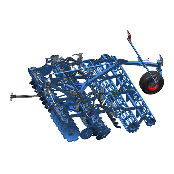
Page 34: Layout And Description
Layout and description LAYOUT AND DESCRIPTION The following assembly groups may be installed on the imple- ment, depending on implement model and national requirements. Overview 1 Lower link connection 2 Concave discs 3 Working depth adjustment for concave discs 4 Rebound harrow 5 Limiting disc 6 Levelling harrow 7 Roller... -
Page 35: Function
Layout and description Function 5.2.1 Lower link connection The lower link connection with its pins and the top link pin are based on standard ISO 730. The lower link connection and the top link pin are used to connect the implement to the three-point linkage of the tractor. -
Page 36: Limiting Discs
Layout and description 5.2.4 Limiting discs The limiting discs prevent the outer front concave discs leaving grooves or crea- ting ridges. The limiting discs limit the flow of soil to the working width of the im- plement. 5.2.5 Rebound harrows The rebound harrows control placement of thrown-up soil and ensure that the following implements are not impeded by accumulations of soil. -
Page 37: Preparations On Tractor
Preparations on tractor PREPARATIONS ON TRACTOR Tyres The air pressure must be identical, particularly on the rear tractor tyres. Under dif- ficult conditions, additional wheel weights should be used or the tyres topped up evenly with water. Refer to the operating instructions from the tractor manufactu- rer. -
Page 38: Required Hydraulic Equipment
Preparations on tractor Required hydraulic equipment The implement is supplied as standard with separate hydraulic connections for each consumer. The protecting caps for the hydraulic connections are colour- coded and the hydraulic connections themselves are alphanumerically coded. For operation of the specific hydraulic equipment listed below, the tractor must be equipped with the following control units: Trac- Single acting... - Page 39 Preparations on tractor Loss of the implement The tractor's three-point linkage category and the categories of WARNING the lower link connection and top link pins must match. Otherwise, the lower link connections and the top link pins may slip out of the linkage when driving over uneven ground or due to vibrations.
-
Page 40: Hydraulic System
Preparations on tractor The table below shows the permitted maximum tractor power and dimensions for each category as per ISO 730-1. Tractor power* Cat. Pintle diameter of cross Length of cross shaft shaft (mm) (shoulder distance) (mm) 36.6 36.6 50.8 * The indicated values refer to the design of the lower link connections. -
Page 41: Coupling And Uncoupling
Preparations on tractor 6.7.3 Coupling and uncoupling Lowering or raising the three-point linkage CAUTION If the three-point linkage moves uncontrollably due to an incorrect setting or operation, the operator may be injured. To couple or uncouple the device, always switch the tractor hydraulics to position control. -
Page 42: Preparing The Implement
Preparing the implement PREPARING THE IMPLEMENT Setting up the category of the lower link connections The category of the lower link connections is set up through the insertion position of the pins (1) and spacer rings (2). The implement can be adapted to three-point linkages or quick-hitch couplings of various tractors. -
Page 43: Attaching The Implement
Attaching the implement ATTACHING THE IMPLEMENT Risk of injury when coupling the device WARNING There is a risk of body parts being crushed between the tractor and device The tractor must be secured against unintentionally rolling away. Never actuate the hydraulic system of the tractor if there are people between the tractor and device. -
Page 44: Attachment
Attaching the implement Danger to life due to unsecured connection between lower link and lower link connection If the connection between the lower link and the lower link connection is not secured, the pin of the lower link connection may slip out. DANGER The implement may fall down laterally and injure or kill people in the immediate vicinity. - Page 45 Attaching the implement Connect the hydraulic hoses to the trac- tor. o Make certain they are assigned correctly. o Note the hydraulic system la- bels. Connect the electrical lines to the tractor. Back the tractor up to the implement. ...
-
Page 46: Mounting Positions
Attaching the implement Activate the function of the depth and transport wheel When detached, secure the depth and transport wheel in lifted out position with a pin (3a). To activate the depth and transport wheel: Remove the linch pin of the pin. ... -
Page 47: Upper Control Link
Attaching the implement Upper control link Risk of injury from unsecured upper control link pin If the upper control link pin is not secured, it may slip out or get CAUTION lost. As a result, the implement may fall down or be damaged. ... - Page 48 Attaching the implement The position of the top link (1) can be ad- justed as follows: Lower the implement completely. Switch the tractor's three-point linkage to position control. Activate the tractor's three-point linkage until there is no load on the top link pin. ...
-
Page 49: Driving On Public Highways
Driving on public highways DRIVING ON PUBLIC HIGHWAYS General information A proper lighting system, identification and equipment must be on the implement, if it is to be transported on public roads. The country-specific valid laws and regu- lations pertaining to driving on public roads must be observed. Preparation for driving on public roads Before commencing a journey on public roads, the following components and sa- fety equipment must be checked to ensure they are working properly and can be... - Page 50 Driving on public highways Depth and transport wheel When lifting out the implement, the weight of the depth and transport wheel is trans- ferred without the need of an auxiliary spool valve. On even ground: Lift out the implement until the indicator of the depth and transport wheel’s depth display is within the "OK"...
-
Page 51: Permitted Transport Speed
Driving on public highways Axle load ballasting Ensure sufficient front axle load of the tractor (see "Axle loads, page 24") Road travel after application in the field: Clean the implement roughly and remo- ve sticking soil. Permitted transport speed The following table shows the permitted maximum transport speeds depending on the tyres and the equipment of the implement. -
Page 52: Operation
Operation OPERATION Read and follow the information in the section entitled "Safety and protection measures". CAUTION The implement may only be used, maintained and repaired by people who are familiar with it and who are aware of the ha- zards involved. -
Page 53: Working Depth
Operation 10.1 Working depth The working width adjustment takes place, depending on the implement equipment, mechanically using pins or hydraulically. Risk of accident due to freely rotating rollers WARNING When climbing onto freely rotating rollers, there is a risk of body parts being crushed and trapped. - Page 54 Operation Release the bottom pins. o Remove the linch pins. Select a hole for the desired working depth. Insert the bottom pins into the desired holes in the adjusting plates. Secure pins with linch pins. The pins in holes 1 to 5 determine the lo- wering depth of the rollers when the im- plement is lifted out.
-
Page 55: Hydraulic Working Depth Adjustment
Operation 10.1.2 Hydraulic working depth adjustment The working depth is adjusted with a spool valve of the tractor through the hydraulic rams. The set working depth can be read off on the scale. A graduation mark on the scale corresponds to an approx. 2 cm change in working depth. - Page 56 Operation Pull the pin (3) of the wheel bracket up- wards against the spring pressure. Swivel the wheel bracket (4) with the ou- ter concave disc (5) forwards. Secure the wheel bracket with the pin (1) of the limiting disc in retracted position. ...
-
Page 57: Extending The Outer Concave Discs
Operation Ensure that the outer concave discs are retracted fully. Lock the spool valve of the tractor. 10.2.2 Extending the outer concave discs Extend the outer concave discs for working in the field: Extend mechanically Lift out the implement. ... - Page 58 Operation Raise the limiting disc (2). Secure the limiting disc with the pin (1). Secure the pin with linch pin. Extend hydraulically Lift out the implement. Extend the wheel brackets (4) with the outer concave discs (5) using the spool valve of the tractor.
-
Page 59: Adjusting The Outer Concave Discs
Operation o The hook (6) of the hydraulic ram (2) always hooks in behind the hexagon bolt (7). 10.2.3 Adjusting the outer concave discs The outer concave discs are used to opti- mise edge levelling. The outer concave discs feature a three- stage height adjustment. -
Page 60: Rebound Harrow
Operation Loosen the nuts of the bolted connec- tions (2, 3). Move the limiting disc (1) to the desired position. o ATTENTION: If the bolted connections are removed, hold on tight to the limiting disc. Screw on new self-locking nuts and tigh- ten. -
Page 61: Levelling Harrow
Operation Implements with depth and transport wheel: The height adjustment takes place via the levers (1) of the harrow adjustment, on the left and right-hand side of the implement. To change the height of the rebound harrow (2): Turn the levers on the left and right-hand side of the implement alternately to the desired direction. -
Page 62: Mounting And Dismantling The Weed Harrow
Operation Implements with depth and transport wheel: The height adjustment takes place via the levers (1) of the harrow adjustment, on the left and right-hand side of the implement. To change the height of the harrow (2): Turn the levers on the left and right-hand side of the implement alternately to the desired direction. - Page 63 Operation Mounting the weed harrow The weed harrow (1) must always be mounted on a trailing roller. Brackets (2) and U-bolts (3) are available for mounting. There is one harrow segment for each trai- ling roller segment. Example image Position both U-bolts (3) on the support- ing frame (5) of the roller.
-
Page 64: Adjusting The Weed Harrow
Operation 10.6 Adjusting the weed harrow Adjusting the angle Turn the screw (1) with the spanner Clockwise = flat angle Anticlockwise = steep angle The yoke (2) moves up or down with the harrow tube. The angle of the harrow changes. - Page 65 Operation Swivel the holder (3) to the required height. Example image To fix the holder in the swivelled in positi- Insert the pin (2) into the matching not- ches above and below the holder. Example image Secure the pin with a linch pin (1). ...
-
Page 66: Rollers
Operation 10.7 Rollers 10.7.1 General information The implement can be fitted with different roller types, see the following table. The rollers control the implement at the working depth. Irrespective of the roller type used, the soil is more or less recompacted or more or less crumbled. Rubin 10 Roller type 400 U... -
Page 67: Knife Rollers
Operation 10.7.2 Knife rollers Adjusting the knife roller Blade working depth On both sides of the roller: Take any loads off the upper bolt (4). o Turn the screw (3) clockwise to do so. Release the upper bolt (4). ... - Page 68 Operation Short deflection travel (standard): Insert the lower bolt (5) into the hole in the adjustment plate (2). o Choose the hole directly below the support plate (1). o The knives operate more ag- gressively if the deflection trav- el is short.
-
Page 69: Pressure Load On Rollers - Soil Penetration
Operation On both sides of the roller: Remove the screws from the holes (6). Reposition the knife bar (8) in the lower mounting position (7). Blade position There are two mounting positions for the blades (11) on the knife bar (8): ... - Page 70 Operation Top link The mounting position of the top link exerts an influence on the lift height, the soil penetration and the roller pressure. The hydraulic system of the three-point linka- ge on the tractor must be switched to the float position. Top link position PenetrationLift height...
-
Page 71: Turning At The Headland
Operation The lower the top link is mounted on the implement's headstock, the greater the pressure load on the rollers – resulting in better soil penetration. The higher the top link is mounted on the implement's headstock, the lower the pressure load on the rollers –... -
Page 72: Working Speed
Operation Before turning at the headland Raise the implement all the way. After turning at the headland Lower the implement when driving straight ahead, at a suitable speed, to the preset working depth. 10.9 Working speed A sufficiently high working speed is required to achieve good work results. -
Page 73: Cleaning And Care
Cleaning and care CLEANING AND CARE 11.1 Cleaning with a high-pressure cleaner When cleaning with a high-pressure cleaner, ensure that water does not get into the electrical and electronic components. Do not point the jet of the high-pressure cleaner directly at the bearings. -
Page 74: Detaching The Implement
Detaching the implement DETACHING THE IMPLEMENT Select an even, solid surface for de- tachment. Switch the tractor's hydraulic system to position control mode. Lower the implement. o Both concave disc rows and the roller must be on the ground. - Page 75 Detaching the implement Disconnect the lower link from the lower link connections. Drive the tractor about 40 cm away from the implement. Secure the tractor to prevent it from rol- ling away. Depressurise the auxiliary spool valves of the hydraulic system.
-
Page 76: Put The Implement Out Of Operation
Put the implement out of operation PUT THE IMPLEMENT OUT OF OPERATION 13.1 Shutting down the implement in an emergency In an emergency shut down the implement via the tractor. Switch the tractor engine off. Remove the ignition key. Damage caused by improper storage of the implement If incorrectly or improperly stored, the implement may be dam- CAUTION... -
Page 77: Maintenance And Repairs
Maintenance and repairs MAINTENANCE AND REPAIRS 14.1 Special safety instructions 14.1.1 General Risk of injury when carrying out maintenance and repair work There is always the risk of injury when carrying out maintenance and repair work. WARNING Use suitable tools, suitable climbing aids, platforms and support elements. -
Page 78: Immobilise The Implement For Maintenance And Repairs
Maintenance and repairs 14.1.4 Immobilise the implement for maintenance and repairs Risk of accidents when tractor starts up Injuries may occur if the tractor starts moving during maintenance and repair work. Switch off the tractor engine before carrying out any work on the WARNING implement. -
Page 79: Working Under The Raised Device
Maintenance and repairs 14.1.7 Working under the raised device Risk of accident due to lowering and extending of compo- nents and devices It is extremely dangerous to work under raised or next to retracted components and devices. WARNING Always secure the tractor to prevent it from rolling away. ... -
Page 80: Environmental Protection
Maintenance and repairs Risk of back injuries If your posture is not correct when installing or fixing heavy or WARNING cumbersome components, you may suffer back injuries which re- quire long convalescence. Installation and maintenance work may be carried out by trained and instructed personnel only. -
Page 81: Maintenance Intervals
Maintenance and repairs For all lubrication work, use the listed environmentally-compatible lub- ricants only. Ensure that all chain links, pins, guides, etc. can move freely. Lubricate all moving parts using high-grade multipurpose grease or multipurpose oil. Service the implement in line with the "Maintenance intervals" section. Additionally after the season is over ... -
Page 82: Daily Check
Replace damaged or defective hydraulic hoses im- mediately. The hydraulic hoses must be replaced 6 years after the date of manufacture at the latest. Only used hydraulic hoses approved by Lemken. Check that all safety equipment is functioning pro- Safety equipment perly. -
Page 83: Lubrication Schedule
Maintenance and repairs 14.4.4 Lubrication schedule For all lubrication work use the high-grade grease Olistamoly 2 or an equivalent high-grade grease only. Wheel arm bearing (a) Wheel hub (b) Greasing of components Greasing of pins Greasing of piston rods using acid-free grease Blank surfaces of the levelling harrow... -
Page 84: Overview Of Lubricating Points
Maintenance and repairs 14.4.5 Overview of lubricating points Depth and transport wheel Wheel arm bearing (a) Wheel hub (b) -
Page 85: Tightening Torques
Maintenance and repairs 14.5 Tightening torques 14.5.1 General Secure self-locking nuts that have been loosened against working themselves loose again by: Replacing them against new self-locking nuts Using lock washers Using locking compounds such as Loctite The tightening torques set out below refer to screw connections that are not specifically mentioned in these operating instructions. -
Page 86: Wheel Bolts And Wheel Nuts
Maintenance and repairs 14.5.3 Wheel bolts and wheel nuts Diameter / thread [Nm] M18 x 1,5 M20 x 1,5 M22 x 1,5 14.6 Check the connections to the tractor 14.6.1 Hydraulic connections Risk of accidents due to escaping hydraulic fluid Hydraulic fluid which is ejected under high pressure (hydraulic oil) WARNING can penetrate the skin and cause serious injuries. -
Page 87: Replacing The Harrow Tines On The Rebound Harrow
Maintenance and repairs 14.7 Replacing the harrow tines on the rebound harrow The implement must be raised to replace the harrow tines. Secure the implement so that it does not sink accidentally. Remove the bolts (1) on the harrow tine holder. -
Page 88: Replacing Levelling Harrow
Maintenance and repairs 14.8 Replacing levelling harrow Lift out the implement. Fold out lateral parts of folding imple- ments. Secure the implement against lowering. Dismount screw (1). Remove levelling harrow (2). Push on new levelling harrow (2). ... - Page 89 Maintenance and repairs Correctly dispose of the removed discs, screws and nuts ac- cording to the applicable disposal regulations. Dispose of the wiped grease and the cleaning cloths according to the applicable disposal regulations. Lift out the implement. ...
-
Page 90: Readjusting Locking Device Of The Outer Concave Discs
Maintenance and repairs 14.10 Readjusting locking device of the outer concave discs Outer concave discs with hydraulic fol- ding: The locking hook (6) on the hydraulic cy- linder (2) must grip free of play behind the hexagon pin (7). The hexagon pin must be positioned on the flank of the locking hook (b). -
Page 91: Replacing Shear Pin
Maintenance and repairs Readjusting locking device Loosen nuts (8, 9). o The hexagon pin (10) turns freely. Unscrew hexagon pin (10) until the following conditions have been met: o The screw head is in contact with the stop on the basic fra- me (a). -
Page 92: Readjusting The Working Brake Of The Depth And Transport Wheel
Maintenance and repairs 14.11 Readjusting the working brake of the depth and transport wheel The depth and transport wheel is fitted with a tension disc as the working brake to pre- vent a rocking motion of the depth and transport wheel. The tension disc must be readjusted with increasing wear of the brake lining. - Page 93 Adjust the air pressure according to the specifications in the ope- rating instructions. The PR figure or the load / speed index and the tread designation are stamped into the tyres. Rubin 10 U – with depth and transport wheel Tyre size Manufacturer Profile...
-
Page 94: Scrapers
Maintenance and repairs 14.13 Scrapers 14.13.1 Scrapers on rubber ring roller The scrapers (1) on the rubber ring rollers (2) have slots to allow adjustment. Release the self-locking nut (3). Adjust the relevant scraper on the roller so that it has a clearance of between 8 and 12 mm to the rings. -
Page 95: Technical Data
Technical data TECHNICAL DATA 15.1 Dimensions Rubin 10 U* – without depth and transport wheel Minimum length approx. [mm] 3060 Maximum length approx. [mm] 3800 2500 3000 3500 4000 Approx. working width [mm] Approx. transport width [mm] 2996 Implement height*** approx. [mm] 1563 Centre of gravity** approx. -
Page 96: Implement Weights
Technical data 15.2 Implement weights Rubin 10 U* – without depth and transport wheel Minimum gross weight approx. 2063 [kg] Maximum implement weights ap- 2462 prox. [kg] * To determine the actual implement weights: Weigh Rubin 10 U* – with depth and transport wheel Minimum gross weight approx. -
Page 97: Permitted Maximum Speed
Technical data 15.5 Permitted maximum speed Rubin 10 U Without depth and transport wheel permitted maximum speed of the tractor [km/h] With depth and transport wheel [km/h]... -
Page 98: Noise, Airborne Sound
Noise, Airborne Sound NOISE, AIRBORNE SOUND The noise level of the implement does not exceed 70 dB (A) during work. NOTES As the version of equipment is depending from the order, the equipment of your implement and its description concerned may deviate in some cases. To ensure a continuously updating of the technical features, we reserve the right to modify the design, equipment and technique. -
Page 99: Index
Index INDEX "Adjusting ......................57 "Air ........................91 "Attachment" ....................... 42 "Hydraulic ......................36 "Levelling ......................59 "Lubrication ......................81 "Rebound ......................58 "Rollers" ......................64, 67 "Secure ....................... 72 "Technical ......................93 "Transport ......................49 "Tyres" ....................... 91 "Weed ......................60, 62 "Working ...................... - Page 100 Index Warning signs ..................... 16...
Need help?
Do you have a question about the Rubin 10 U and is the answer not in the manual?
Questions and answers