
Related Manuals for LEMKEN RUBIN 10


Summary of Contents for LEMKEN RUBIN 10
- Page 1 OPERATING INSTRUCTIONS COMPACT DISC HARROW RUBIN 10 Rubin 10/1000 KUA en-GB | Item no. 17517289 | BA 00/2023-06...
- Page 2 Pass these instructions to all users / owners. Original instructions © 2023 | This documentation is copyright protected. The copyright remains with LEMKEN GmbH & Co. KG, Weseler Strasse 5, D-46519 Alpen. The texts, diagrams and drawings must not be duplicated, distributed or disclosed in any other way,...
-
Page 3: Table Of Contents
Table of contents Table of contents About these instructions............................1 1.1 Introduction................................. 1 1.2 Target groups..............................3 1.3 Applied presentations............................. 3 1.3.1 Signal words and hazard statements...................... 3 1.3.2 Symbols and text markings........................4 1.3.3 Direction specifications..........................4 1.4 Further applicable documents........................5 Safety.................................... - Page 4 Table of contents 5.2 Preparing for road travel..........................38 5.3 Preparing the lighting equipment for road travel................40 Operation................................... 42 6.1 Basic operation..............................42 6.1.1 Folding the machine..........................42 6.1.2 Operate the compressed air brake......................44 6.2 Adjusting the machine..........................47 6.2.1 Adjusting the working depth and position of the concave discs..........
- Page 5 Table of contents 9.4.3 Replacing the levelling harrow....................... 80 Troubleshooting and error correction......................81 10.1 Finding and eliminating errors correctly....................81 10.2 Error - Cause - Remedies at a glance...................... 81 Shutdown and disposal............................83 11.1 Final decommissioning..........................83 11.2 Recycling and disposal ..........................84 Technical data................................
- Page 6 Table of contents en-GB | Item no. 17517289 | BA 00/2023-06...
-
Page 7: About These Instructions
About these instructions About these instructions Introduction These operating instructions are important and belong to the machine's scope of delivery. These operating instructions must be available to the user at the place of use. Always read chapter "Safety" before using the machine for the first time. - Page 8 About these instructions Validity range These operating instructions describe operation of the machine after initial commissioning by the LEMKEN sales partner and handover to the operator. Prior to operation, initial commissioning and instruction in operation, setting/adjustment and maintenance must have been carried out.
-
Page 9: Target Groups
About these instructions Target groups The target groups of these operating instructions are operators, users and service personnel of the machine. The target groups must meet the requirements for the qualification of the personnel. Ä Chapter 2.2 ‘Requirements of operators, users and service personnel’ on page 7. -
Page 10: Symbols And Text Markings
About these instructions 1.3.2 Symbols and text markings Symbol, text Meaning marking In front of and in texts Marking for routine maintenance tasks ● Activities that demand the help of service staff. Listing Position numbers [1], Example: ‘Settings’ Software element Example: [OK] Softkey, key, switch and button [kg]... -
Page 11: Further Applicable Documents
The documents are regularly updated and brought into line with any changes. The latest versions of the documents can be found in the LEMKEN Online Information System (LEONIS). Users can access LEONIS directly via the QR code or the LEMKEN website. -
Page 12: Safety
Safety Safety Machine limits Intended use The machine is used for soil cultivation on agricultural land. The machine is used for soil cultivation on agricultural land. It may only be used in accordance with the recognised rules of good agricultural practice. The permitted working depth is limited to the cultivatable soil horizons. -
Page 13: Requirements Of Operators, Users And Service Personnel
Safety Hazardous area The machine and the area in the immediate vicinity of the machine is deemed a hazardous area. This includes the space over the entire width, length and height of the machine, as well as an additional safety distance of two metres to the machine. -
Page 14: General Safety Information
Safety General safety information Operating instructions The operating instructions are part of the machine. The machine is intended exclusively for use in accordance with these operating instructions. Applications of the machine not described in these oper‐ ating instructions may result in personal injury or death or property damage. - Page 15 Safety Safety equipment Existing and fully functional safety devices protect against death or serious personal injury. Keep the labels legible and renew them, if necessary. ► Replace damaged safety devices. ► Install dismantled safety devices before commissioning. ► Move the safety devices to the protective position. ►...
- Page 16 Safety Hydraulic assembly The hydraulic assembly might be under high pressure. Hydraulic oil leaking under pressure can penetrate through the skin into the body. Injury to body parts, face, eyes and unprotected skin may result. The hydraulic assembly may be hot. The hydraulic oil is harmful to health.
-
Page 17: Safety Information On Hazardous Areas Of The Machine
Safety Safety information on hazardous areas of the machine Area between the tractor and When standing between the tractor and machine, there is a risk due to machine tractor movements or sudden machine movements. Secure the tractor against rolling away. ►... - Page 18 Safety Moving hazardous area The hazardous area of the machine during operation. Moving hazardous area The hazardous area includes the area in driving direction across the entire width of the machine. There must be NO persons in the hazardous area. If there are persons in the hazardous area, may result in death or injury to persons.
- Page 19 Safety Folding range Hazardous areas when folding the implement There should be NO persons present in the folding range. If persons are present in the folding range, it may result in death or serious injury. Lateral sections may, due to their height touch overhead lines during the folding processes and cause flashovers.
-
Page 20: Safety Information On Structural Modifications
Safety Safety information on structural modifications Structural modifications Structural modifications and extensions can impair the functionality and operational safety of the machine. This may result in death or injuries. Auxiliary equipment and spare parts must comply with the manufactur‐ er's requirements. Modifications and conversions may only be carried out with the ►... - Page 21 Safety Behaviour during flashover of over‐ Flashovers cause high electrical voltages on the outside of the tractor- head lines machine combination. Large voltage differences occur on the ground around the tractor-machine combination. Large steps, lying down or supporting yourself on the ground may cause life-threatening electrical currents (step voltage).
- Page 22 Safety Road travel The user operates the machine via control elements such as tractor control units, touch screen, buttons or joystick. Touching the control elements may trigger functions and machine movements, even if touching the control elements was not intended. Disabling machine functions before driving on the road.
-
Page 23: Design And Description
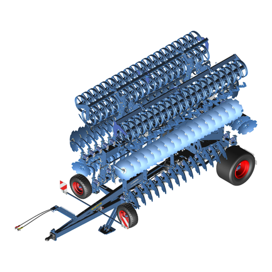
Design and description Design and description Machine overview INFORMATION Depending on the equipment of the machine and country-specific requirements, the assembly groups described below may be present on the machine. Drawbar with hitch Rollers Line and hoses Lateral section - left Support wheels Axle with wheels Concave discs - first row... - Page 24 Design and description Hydraulic drawbar Drawbar eye Stand The drawbar eye is an example of a hitch for a machine with a hydraulic drawbar to a tractor. The hydraulic drawbar is equipped with a hydraulic stand The hydraulic drawbar optionally features either a drawbar eye or a ball-shaped coupling and requires a tractor with a tractor drawbar or hitch ball.
-
Page 25: Machine Safety
Design and description Machine safety 3.2.1 Position of the label Rubin 10 - Label overview Reading the operating instructions Hydraulic equipment Turn off the engine Lashing points Area between the tractor and machine Sling points Overhead lines Jacking points Hydraulics label 3.2.2... - Page 26 Design and description Reading the operating instructions Incorrect use or operation of the machine can result in death or serious injury. Before commissioning: Read and observe the operating instructions. ► Follow the instructions for action. ► Turn off the engine A tractor with the engine running can cause unintentional movements.
- Page 27 Design and description Folding range Danger due to machine components being folded out. This will result in death or serious injury. When the tractor is running: Do NOT remain in the folding range of the machine. ► Area between the tractor and machine A tractor with the engine running can make or cause unintentional movements.
- Page 28 Design and description Jack positioning points Positioning points for jack Lifting points for fork-lift truck Lifting points for fork-lift truck Hydraulic equipment Control units Coupling Line Consumer Single Double Free acting acting return Blue +/– Trailer ● Green +/– Lifting device ●...
-
Page 29: Safety Devices
Design and description 3.2.3 Safety devices 3.2.3.1 Lighting equipment and identification The marking and the lighting equipment increase safety while driving on the road. For public road traffic, the machine must be equipped with the fol‐ lowing components in accordance with national regulations: Marking Lighting equipment Front marking... - Page 30 Design and description Warning board Depending on national regulations, a warning board may be required for slow-moving vehicles. 3.2.3.2 Lateral safety guards In transport position, protective gratings offer protection against pro‐ truding outer edges. The protection extends to a height of 2 m (meas‐ ured from the ground).
- Page 31 Design and description 3.2.3.4 Stabilisation Stand Wheel chocks en-GB | Item no. 17517289 | BA 00/2023-06...
-
Page 32: Solo Axle
Design and description 3.2.3.5 Protection against unauthorised use The protection against unauthorised use ensures that only authorised persons can attach the machine to a tractor. The following versions are available: Protection against unauthorised use for ball-shaped couplings Protection against unauthorised use for drawbar eyes 3.2.3.6 Safety chain For machines without a braking system, a safety chain may be required,... -
Page 33: Iq Contour Rubin
Design and description iQ contour Rubin Overview Hydraulic ram lateral section (left) Joint plate iQ contour Rubin Hydraulic ram lateral section (right) Pivot point lateral section (right) Hydraulic ram iQ contour Rubin Pivot point lateral section (left) Contour adjustment takes place automatically when the iQ contour Rubin function is switched on. -
Page 34: Trailer
Design and description Trailer The trailer is positioned in front of the folded out working section when working in the field. The trailer is positioned behind the folded in working section when driving on public roads. To leave no tracks, the trailer is lifted while working on the field. The permissible tyres and wheels are shown in the technical data. -
Page 35: Touch Wheels
Design and description Brake force regulator Brake cylinder Guiding screw Guiding screw retainer Piston rod Brake lever Touch wheels The touch wheels mounted on the outside of the frame stabilise the machine during soil cultivation. The touch wheels are used for sensing only. -
Page 36: Limiting Discs
Design and description Tool Description Side shields The side shields limit the lateral soil flow. Rollers The rollers ensure reconsolidation and additional crumbling of the soil. When the machine is lowered for working, the rollers bear the weight of the machine and ensure precise depth control. The permissible roller types are shown in the technical data. -
Page 37: Commissioning
Scope of delivery and equipment of the machine may vary depending on the configuration of the purchase order. 1. Make certain that all LEMKEN original parts are present according to the purchase order. 2. Make certain that all parts are undamaged and correctly mounted (see corresponding mounting instructions if applicable). -
Page 38: Preparing Braking System
Commissioning Checklist Electrical connections An electrical connection must be available on the tractor Ä Chapter 12.7.1 for each consumer. ‘Electrical connections’ on page 87 Hydraulic connections A hydraulic connection and a suitable control unit must be Ä Chapter 12.7.2 Hydraulic power available for each consumer. -
Page 39: Attaching The Machine
Commissioning Remove the guiding screws WARNING Risk of injury due to stored mechanical energy The spring in the brake cylinder operates under high pre-tension. Undoing the screws at the brake cylinder releases the straps . The brake cylinder will then fly apart at an explosive rate. - Page 40 Commissioning 4. INFORMATION: Ensure that the hydraulic connections and hydraulic plugs are clean. Connect the hydraulic hoses for the hydraulic stand to the tractor. 5. Using the hydraulic stand, adjust the height of the drawbar eye to the height of the tractor drawbar. 6.
- Page 41 Commissioning 5. Use the hydraulic stand to set the ball-shaped coupling approx. 5 cm higher than the hitch ball. 6. Move the tractor slowly backwards until the ball-shaped coupling (machine) is positioned above the hitch ball (tractor). 7. Use the hydraulic stand to slowly lower the ball-shaped coupling onto the hitch ball.
- Page 42 Commissioning 9. If the machine has a compressed air brake: Initially connect the yellow compressed air connection the tractor. Then connect the red compressed air connection to the tractor. 10. Prepare for driving. Ä ‘Preparing for driving’ on page 36 YELLOW Preparing for driving 1.
-
Page 43: Road Travel
Road travel Road travel Information on road travel INFORMATION Laws on driving on public roads differ in many countries. Pay particular attention to local laws and regulations regarding the ► following points: Driving on public highways Maximum permissible transport height Maximum permissible transport width Maximum permissible transport weight Lighting equipment... -
Page 44: Preparing For Road Travel
Road travel Preparing for road travel Check and prepare the following assembly groups, safety devices and functions in accordance with these operating instructions before each road travel. Adhere to the following sequence: Checklist Connections of the Attach the machine to the tractor. Pre‐ Ä... - Page 45 Road travel Checklist Lighting equipment Ensure full functionality of the lighting Ä Chapter 5.3 ‘Preparing the equipment in accordance with national lighting equipment for road travel’ regulations. on page 40 Transport dimensions Ensure that the maximum permissible Ä Chapter 12.2 ‘Dimensions’ transport dimensions are not exceeded.
-
Page 46: Preparing The Lighting Equipment For Road Travel
Road travel 2. Push the safety guard with the holder into the respective device INFORMATION: The safety guard must cover the cutting edge of the lowest concave disc 3. Hook the tensioning strap into the safety guard. 4. Fasten the other end of the tensioning strap to the device with the hook. - Page 47 Road travel Testing the lighting equipment 1. Activate the direction indicator in the tractor. 2. Check the tell-tale lights in the tractor. ð If the tell-tale light for the direction indicator on the tractor and the tell-tale light for the direction indicator on the machine flash, the lighting equipment has been con‐...
-
Page 48: Operation
Operation Operation Basic operation 6.1.1 Folding the machine DANGER Potentially fatal electric shock from overhead lines When the machine is being folded in or out, it can reach the height of overhead lines. An electrical flashover between the lines and the machine can occur, leading to a potentially fatal electric shock or fire. - Page 49 Operation 3. Ensure that the hydraulic hoses of the folding cylinder are undam‐ aged. 1. Before folding in the lateral parts, fully lift the machine at the front and the rear. 2. Hold additional control units in the 1st pressure position until: the lateral parts have been folded in.
-
Page 50: Operate The Compressed Air Brake
Operation 4. Set the control unit to the float position. Do not actuate the control unit any more. 5. Lower the machine. ð The machine stands on the roller and not on the trailer. ð Machine has been folded out. 6.1.2 Operate the compressed air brake Couple and uncouple the brake hoses... - Page 51 Operation Operate the parking brake The parking brake is used by the user to secure the implement against rolling away. Release the parking brake 1. Push in the red button of the park valve . 2. Check adjustment of the brake force regulator. If necessary, adjust setting to the axle load of the implement.
- Page 52 Operation Information on operating pressure If the operating pressure of the compressed air brake falls below Brake cylinder Piston rod 4.3 bar (±0.3 bar), the spring of the brake cylinder activates the Brake lever braking system via the piston rod and the brake lever en-GB | Item no.
-
Page 53: Adjusting The Machine
Operation Adjusting the machine 6.2.1 Adjusting the working depth and position of the concave discs ATTENTION Material damage due to excessive working depth If the working depth is too great, the machine and the tractor may be damaged due to overloading. –... - Page 54 Operation Adjusting the working depth of the rear concave discs The red pointer shows the current depth adjustment of the rear con‐ Current depth adjustment indicator cave discs on the scale from 1 to 10. The scale indication is a guide value. The working depth display may fluctuate while working due to actual oscillation.
- Page 55 Operation Adjusting the working depth of the INFORMATION front concave discs For an even working result, the front and rear concave discs should be adjusted to the same height. Precondition: √ The working depth of the rear concave discs has been adjusted. 1.
- Page 56 Operation Synchronising the memory function of the working depth Preconditions: √ Machine is folded in. Ä Chapter 6.1.1 ‘Folding the machine’ on page 42 √ Working depths of the front and rear concave discs have been adjusted. 1. Actuate the following control units on the tractor simultaneously: Working depth Lifting device 2.
-
Page 57: Adjusting The Outer Concave Discs
Operation 6.2.2 Adjusting the outer concave discs WARNING RISK OF ACCIDENT due to the tractor rolling away or sudden machine movement When standing between the tractor and machine, there is a risk of the tractor rolling away or of sudden machine movements. -
Page 58: Adjust The Brake Force Regulator
Operation 6.2.3 Adjust the brake force regulator The brake force regulator has seven adjustment positions. The adjustment positions not approved for this implement are mechanically locked and must not be used. ► Adjust the braking force with the lever of the brake force regu‐ lator. -
Page 59: Adjusting The Rebound Harrow
Operation 6.2.4 Adjusting the rebound harrow WARNING RISK OF ACCIDENT due to the tractor rolling away or sudden machine movement When standing between the tractor and machine, there is a risk of the tractor rolling away or of sudden machine movements. - Page 60 Operation Adjustments with perforated plate 1. Undo the screw connections on both sides of the rebound harrow Rebound harrow 2. Move the perforated plates on the lateral parts vertically and Perforated plate in longitudinal direction. Screw connections Lateral part Select the same holes on the right and left. For the front position: Use the holes For the rear position: Use the holes Do NOT use the hole...
- Page 61 Operation Adjustment in longitudinal direction: 1. Undo the screw connections on both sides of the rebound harrow 2. Move the toothed racks on the lateral parts in longitudinal direction. For the front position: Use the holes For the rear position: Use the holes 3.
-
Page 62: Adjusting The Levelling Harrow
Operation 6.2.5 Adjusting the levelling harrow WARNING RISK OF ACCIDENT due to the tractor rolling away or sudden machine movement When standing between the tractor and machine, there is a risk of the tractor rolling away or of sudden machine movements. -
Page 63: Adjusting The Limiting Discs
Operation 6.2.6 Adjusting the limiting discs The limiting discs feature a three-stage height adjustment. With increasing wear: Set the limiting discs lower. Secure the tractor and machine to prevent them from rolling away. Secure lifted parts to prevent them from lowering. Remove the ignition key. -
Page 64: Working With The Machine
Operation Working with the machine 6.3.1 Standard procedure INFORMATION The trailer is lifted when working. If the pressure load is too high and the rollers thus become clogged or sink into the ground, the trailer can be lowered. Working in the field 1. -
Page 65: Driving On The Headland
Operation Completing working in the field 1. On completion of soil cultivation: Clean the machine and remove coarse dirt. 2. Prepare the machine for road travel. 3. If a machine with memory function of the hydraulic system is parked for a longer period of time: Secure the lateral parts with lashing straps against uninten‐... -
Page 66: Cleaning And Care
Cleaning and care Cleaning and care Cleaning with high-pressure cleaner The user can clean the machine with the high-pressure cleaner. When cleaning, the user must observe the following: ATTENTION Damage due to cleaning with a high-pressure cleaner Components may be damaged when cleaning with a high-pressure cleaner. -
Page 67: Detaching Machine
Detaching machine Detaching machine Detaching the machine 1. If the machine is to be parked in the folded in position: Fold in the machine before detaching. Ä Chapter 6.1.1 ‘Folding the machine’ on page 42 2. For transport to the parking place: Prepare the machine for driving. - Page 68 Detaching machine 14. Position the protecting caps on the connectors of the electrical lines. 15. Place and secure electrical lines in the hose cabinet. ð The machine has been detached. 16. Make sure no parts of the machine get caught on the tractor and are dragged along (e.g.
-
Page 69: Maintenance And Repair Work
Maintenance and repair work Maintenance and repair work Maintaining the machine properly Personnel Certain activities, e.g. working on hydraulic hoses, should only be car‐ ried out by service personnel. These tasks are: Highlighted with the symbol Marked in the SERVICE PERSONNEL column in the maintenance schedule 9.1.1 Preparations... -
Page 70: During The Maintenance And Repair
Maintenance and repair work 9.1.2 During the maintenance and repair To prevent accidents or injuries: Wear protective equipment. ► Use auxiliary equipment, e.g.: ► Suitable tools Climbing aids Supporting elements For dismantling and mounting heavy components: ► Use hoisting gear. Check nuts and screw heads etc. - Page 71 Maintenance and repair work Chap. Task to execute 9.2.3.2 Check the compressed air couplings ● ● 9.2.3.2 Draining compressed air tank ● 9.2.3.2 Clean compressed air filter ● 9.2.3.3 Checking the bolted connections ● ● 9.2.4 Checking the lighting equipment ●...
-
Page 72: Tractor Connection
Maintenance and repair work 9.2.2 Tractor connection Checking the ball-shaped coupling or the drawbar eye Personnel: Service personnel 1. Visual inspection by the user Wear Damage Peculiarities when driving Have a damaged, deformed or worn ball-shaped coupling or drawbar eye replaced immediately. 2. -
Page 73: Check The Compressed Air Couplings
Maintenance and repair work 9.2.3.2 Braking system Maintaining braking system ► Contact a specialist workshop or trained and instructed service personnel to have the braking system maintained. Check the compressed air couplings Visual inspection by the user ► Wear Damage Leak tightness Immediately replace damaged, worn or leaky compressed air couplings. -
Page 74: Clean Compressed Air Filter
Maintenance and repair work Clean compressed air filter Preconditions: √ Machine is standing on a flat surface. √ The tractor parking brake has been activated. √ The tractor engine has been switched off. √ Ignition key has been removed. 1. Secure the machine with wheel chocks to prevent it from rolling away. - Page 75 Maintenance and repair work Press down the screw-in plug using an Allen key Turn screw-in plug by 90°. Allen key 7. In the open position, the spring presses the screw-in plug Screw-in plug upwards. Screw-in plug open 8. Dismantle the components of the compressed air filter: Screw-in plug Spring Filter screen...
-
Page 76: Safety Equipment
Maintenance and repair work Press down the screw-in plug using an Allen key. Turn screw-in plug by 90°. INFORMATION: In the closed position the spring presses the screw-in plug upwards. The screw-in plug closes flush with the edge of the housing. Allen key 14. -
Page 77: Hydraulics
Maintenance and repair work Check marking Ensure proper functioning. ► Checking safety sticker Ensure legibility and integrity. ► Checking other safety equipment Ensure the functionality and integrity of all other safety equipment. ► Check the hydraulic transport locking device Ensure proper functioning. ►... -
Page 78: Electrics
Maintenance and repair work Checking hydraulic connections 1. Check the hydraulic connections for the following when pressure‐ less: Damage Leakages Repair damaged or leaking hydraulic connections imme‐ ð diately or have them replaced. 2. Connect the hydraulic connections pressureless. 3. Check leak tightness of the hydraulic connections under pressure. ð... -
Page 79: Lubricating
Maintenance and repair work Ä Chapter 9.4 ‘Work instructions’ on page 78 Lubricating 9.3.1 Lubrication schedule INFORMATION The lubrication points are colour coded on the machine. Chap. Task to execute 9.3.2 Lubricate the drawbar eye ● ● 9.3.2 Lubricating ball-shaped coupling ●... -
Page 80: Lubricating Components Via Grease Nipples
Maintenance and repair work 9.3.2 Lubricating components via grease nipples INFORMATION Use high-performance lubrication grease with MoS2 solid lubricants (e.g. Castrol Molub-Alloy 370-2). Lubricate braking axle with BPW special long-life grease (ECO-Li 91). Lubricate the drawbar eye Lubricate 1 lubricating point at the drawbar eye ►... - Page 81 Maintenance and repair work Lubricating wheel bearings ► Lubricate one lubricating point at the wheel bearing Wheel bearing lubricating point Lubricating the touch wheels ► Lubricate two lubricating points at the touch wheels Lubricating point of touch wheels Lubricating hydraulic rams Lubricate two lubricating points at each hydraulic ram.
- Page 82 Maintenance and repair work Lubricating folding joints of the lat‐ eral sections Lubricate four lubricating points in the joints of the lateral sections. ► Lubricating the joints of the trailer Lubricate two lubricating points in the joints of the trailer. ►...
-
Page 83: Greasing Components
Maintenance and repair work Lubricating bearings at the drawbar and basic frame Lubricate two lubricating points in the bearings between the ► drawbar and the basic frame. 9.3.3 Greasing components Grease top link pin Dismantle, grease and reassemble the top link pin. ►... -
Page 84: Work Instructions
Maintenance and repair work Lubricate the contact surfaces with a brush. ► Work instructions 9.4.1 Replacing concave discs Preconditions: √ Tractor-machine combination is secured against rolling away. √ The tractor rear lifting gear has been switched to position control. √ The machine has been lifted fully. -
Page 85: Replacing The Harrow Tines Of The Rebound Harrow
Maintenance and repair work 3. Carefully clean the concave disc 1 and bearing flange 2. ATTENTION: After dismantling the concave disc, a section of the bearing is openly accessible. Dirt must not get into this section. 4. Undo the self-locking nuts 3. 5. -
Page 86: Replacing The Levelling Harrow
Maintenance and repair work 9.4.3 Replacing the levelling harrow 1. Fold out lateral parts of folding machines. 2. Lift the machine and secure it against unintentional lowering. 3. Secure the tractor-machine combination to prevent it from rolling away. 4. Remove the ignition key. 5. -
Page 87: 10 Troubleshooting And Error Correction
Troubleshooting and error correction 10 Troubleshooting and error correction 10.1 Finding and eliminating errors correctly INFORMATION Necessary deviations from this procedure are described in the respective chapters on troubleshooting. 1. Park the tractor/machine combination. 2. Secure the tractor-machine combination to prevent it from rolling away. - Page 88 Troubleshooting and error correction Fault description Cause Remedy iQ contour Rubin does There is a fault in the elec‐ If necessary, fix the lateral sections and operate the not work tronics, hydraulics or the sen‐ machine without iQ contour Rubin. sors.
-
Page 89: 11 Shutdown And Disposal
Shutdown and disposal 11 Shutdown and disposal 11.1 Final decommissioning ENVIRONMENTAL PROTECTION Do NOT leave machine parts exposed to weather condi‐ tions for an extended period, as operating materials, etc. could be released into the environment. Precondition: √ Further use of the machine within the meaning of these instruc‐ tions is no longer intended. -
Page 90: Recycling And Disposal
Shutdown and disposal 11.2 Recycling and disposal Special knowledge is required for disposal of machine parts or oper‐ ating materials. 1. Assign qualified specialists for disposal. 2. Recycle machine parts. 3. Dispose of auxiliary materials and operating materials in an envi‐ ronmentally responsible manner. -
Page 91: Technical Data
Technical data 12 Technical data 12.1 About the technical data Machine variants Machine variants may have varying technical data. Different machine variants are potentially distinguished in the technical data by means of abbreviated product designations, e.g. type designa‐ tion on the type plate: Ä... -
Page 92: Permissible Mass And Loads
Technical data 12.4 Permissible mass and loads The maximum permissible total mass, drawbar load and axle load of the machine are listed on its type plate. If the load capacities of the wheels are lower than the permissible axle loads, the permissible axle load is limited to the permissible load capacity of the wheels. -
Page 93: Connection Data
According to DIN ISO 1724 Lighting equipment According to ISO 1185 (Canada, USA) Electronic seed drill con‐ According to DIN 9680 ● trol (with mounted-on LEMKEN seed drill) Voltage tolerance range: 10 V to 15 V en-GB | Item no. 17517289 | BA 00/2023-06... -
Page 94: Hydraulic Connections And Control Units
Technical data 12.7.2 Hydraulic connections and control units Control units Coupling Line Consumer Single Double Free acting acting return Blue +/– Trailer ● Green +/– Lifting device ● +/– Folding ● Black +/– Working depth ● Yellow +/– Stand ● Orange P T LS Contour adjustment... -
Page 95: 12.10 Tyres And Wheels
Technical data 12.10 Tyres and wheels The PR number, the load and speed index and the profile designation have been vulcanised in the tyres. Tyre size Manufac‐ Tread Ply rating Load + Air pressure Rolling cir‐ turer [PR] speed [bar] cumference index [mm]... -
Page 96: 12.12 Connecting Systems At The Machine
Technical data 12.12 Connecting systems at the machine Permissible categories - connecting system at the machine and hitch on the tractor Rubin 10 Tractor * Tractor-machine combi‐ nation Connecting Standard / Size Hitch Standard / Size Swivel angle ± [°]... -
Page 97: 12.13 Permissible Roller Types
Technical data 12.13 Permissible roller types Double roller DRF 400 / 400 DRR 400 / 400 DRF 540 / 400 DRR 540 / 400 Double profile ring roller DPW 540 / 540 en-GB | Item no. 17517289 | BA 00/2023-06... -
Page 98: Index
Index Index Compressed air brake ....28, 89 Operate ......44 Air pressure . - Page 99 Index Driving Hydraulic stand on public roads ..... . . 37 Design and description ....18 Hydraulic transport locking device Check .
- Page 100 Index Top link pin ......77 Synchronise the working depth ... . 50 Lubricating .
- Page 101 Index Protection against unauthorised use ... 26 Solo axle ....... 26 Stabilisation .
- Page 102 Index Tyres Check ......66 Tyres/Wheels Air pressure ......89 Unhitching - machine from tractor .
-
Page 103: Appendix
Appendix Appendix en-GB | Item no. 17517289 | BA 00/2023-06... -
Page 104: A Type Plate Variants
19 Type / Variant / Version the type plate. 20 Technical conditions Permissible total mass [kg]* 21 QR code to call up LEONIS (LEMKEN Online Infor‐ 10 Permissible drawbar load [kg] (axle 0) mation System) 11 Permissible axle load [kg] (axle 1) - Page 105 Type plate variants en-GB | Item no. 17517289 | BA 00/2023-06...
-
Page 106: B Tightening Torques Screws
Tightening torques screws Tightening torques screws Bolted connections, general principles The following tightening torques refer to screw connections not spe‐ cifically mentioned in these mounting instructions. Special tightening torques are indicated in the text. Identify screw connection: – Identification on the screw head –... - Page 107 The friction coefficient of 0.14 ... 0.15 must be complied with. Never tighten with an impact wrench Tightening torques for bolted connections The following tightening torques apply with all bolted connections used by LEMKEN, unless specified otherwise: Screws and nuts made of steel Diameter Strength category 8.8 [Nm*]...
- Page 108 Tightening torques screws Diameter Strength category 8.8 [Nm*] 10.9 [Nm*] 12.9 [Nm*] 1245 1450 1121 1570 1892 1958 2753 3304 * µ = 0.09 Diameter Strength category 8.8 [Nm*] 10.9 [Nm*] 12.9 [Nm*] M8 x 1 22.8 32.0 38.4 M10 x 1 40.9 57.5 68.9...
- Page 109 Tightening torques screws Screws and nuts made of stainless steel Diameter [Nm*] A2-70 A4-80 11.5 19.0 25.5 38.0 51.0 65.0 87.0 * µ = 0.14 Tightening torques for wheel bolts and wheel nuts Implements Diameter / thread [Nm] Every M14 x 1,5 Every M18 x 1,5 Every...
- Page 110 The tightening torques are calculated for the friction values µ specified in the tables. The required tightening torque deviates: – If any screws other than LEMKEN original screws are used. – If screws are re-used. Only use LEMKEN original screws!
-
Page 111: C Calculation Of Axle Load And Ballasting For Mounted Machines
Calculation of axle load and ballasting for mounted machines Calculation of axle load and ballasting for mounted machines The calculation of the axle loads and required ballasting is based on data from the operating instructions for the tractor and machine. The result of the calculation is a guide value for an initial assessment of the axle loads and the required ballasting. - Page 112 Calculation of axle load and ballasting for mounted machines Data acquisition for calculating axle loads Abbreviation Description Value Unit Tractor data from the operating instructions or determined by weighing Permissible gross weight of the tractor [kg] G_zul Permissible front axle load [kg] V_zul Permissible back axle load...
- Page 113 Calculation of axle load and ballasting for mounted machines Minimum ballasting, FrontG Vmin rear-mounted machine Enter the calculated value in the result table. Minimum ballasting, RearG Hmin front mounted machine Enter the calculated value in the result table. Actual gross weight G Enter the calculated value in the result table.
- Page 114 Calculation of axle load and ballasting for mounted machines Results for tractor/implement combination Create a result table for each tractor that is used: Actual value Permitted value Double permis‐ according to calculation according to tractor sible tyre load- or measurement operating instruc‐...
-
Page 115: D Cross Shaft Overview
Cross shaft overview Cross shaft overview To determine the cross shaft or lower link connection: Determine the dimensions shown in the sketch on the machine. Compare the dimensions with the data in the table. The category of the three-point linkage must match with the cate‐ gory of cross shaft or lower link connection. - Page 117 LEMKEN GmbH & Co. KG Weseler Strasse 5 D-46519 Alpen Telephone: +49 2802 81-0 Fax: +49 2802 81-220 Email: info@lemken.com Internet: www.lemken.com...
Need help?
Do you have a question about the RUBIN 10 and is the answer not in the manual?
Questions and answers