Table of Contents

Related Manuals for LEMKEN Vega 12


Summary of Contents for LEMKEN Vega 12
- Page 1 Operating Instructions Trailed Field Sprayer Vega 12 - en - Item no. 17511205 BA_01/01.19 LEMKEN GmbH & Co. KG Weseler Straße 5, 46519 Alpen / Germany Telephone +49 28 02 81 0, Fax +49 28 02 81 220 lemken@lemken.com, www.LEMKEN.com...
- Page 3 However, this brief instruction is not a substitute for thorough study of the operating instructions. These operating instructions will help to familiarise you with the LEMKEN GmbH & Co. KG device and the options available for using it.
- Page 4 Remember that you should only use genuine LEMKEN spare parts. Reproduction parts have a negative influence on the function of the device, have a shorter ser- vice life and present risks and hazards that cannot be estimated by LEMKEN GmbH & Co. KG. They also increase the maintenance costs.
-
Page 5: Table Of Contents
CONTENTS General information ....................12 Liability ......................... 12 Guarantee ........................12 Copyright ........................13 Optional accessories ....................13 Type plate ........................14 Symbols used in the Operating Instructions ............16 Hazard classes ......................16 Information........................16 Environmental protection ................... 16 Indication of passages .................... - Page 6 3.8.1 Lighting system and identification ................29 3.8.2 Activate road mode ....................29 3.8.3 Permissible weight of the implement ................. 30 3.8.4 Checks before driving off ................... 30 3.8.5 Requirements of the tractor ..................32 3.8.6 Correct behaviour in road traffic ................32 Obligation of the operator ..................
- Page 7 Step, platform ......................53 6.10 Filters ........................... 53 6.11 Pump ..........................54 6.12 Control and connection centre .................. 54 6.12.1 Flush valve ......................55 6.12.2 Chemical inductor ....................56 6.12.3 Connections ......................58 6.13 Storage compartment ....................60 6.14 Distance measurement ....................60 6.15 Measuring instruments ....................
- Page 8 Overview ........................76 Attaching the implement .................... 76 8.2.1 Implement with air brake system ................79 8.2.2 Implement with hydraulic braking system ..............80 8.2.3 Conversion of device ....................81 Setting the oil hydraulic system ................82 Mounting and testing the drive shaft ................. 82 8.4.1 Shortening the drive shaft ..................
- Page 9 10.3 Operating terminal ...................... 96 10.4 Filling and emptying the hand wash canister ............97 10.4.1 Filling the hand wash canister ................97 10.4.2 Emptying the hand wash canister ................99 10.5 Filling and emptying the clean water tanks ............100 10.5.1 Filling the clean water tanks .................
- Page 10 11.3.4 Cleaning the main tank and boom ................ 149 11.3.5 Cleaning the agitator and injector system ............152 11.4 External cleaning ....................... 158 11.4.1 Factory-supplied external cleaning system............160 Connection for customer’s own external cleaning system ........161 11.4.2 11.5 Cleaning the filters ....................162 11.5.1 General information ....................
- Page 11 14.5.2 Safety chain ......................181 14.5.3 Sliding tube......................181 14.5.4 Joints ........................182 14.6 Hydraulic hoses ......................182 14.7 Oil filter in electro-hydraulic operation ..............183 14.8 Cleaning the air filter of the air brake system ............183 14.8.1 Preparation ......................183 14.8.2 Venting the compressed air tank ................
- Page 12 15.9 Rims ........................... 207 15.10 Track width ........................ 208 15.10.1 Vega 12/3000 ....................208 15.10.2 Vega 12/4000 and 5000 ..................209 15.11 Drive shaft ........................210 15.12 Pumps ........................211 15.13 Spray fluid system ....................212 15.14 Boom .......................... 214 15.14.1...
- Page 13 15.15 Hydraulic hoses ......................215 15.16 Oil hydraulics ......................216 15.17 Electronic pressure display ..................216 15.18 Filter ........................... 217 15.19 Tank volume ......................217 15.20 Noise, airborne sound ....................217 16 Appendix ........................ 218 16.1 General information about nozzles ................218 16.2 Nozzle field of application ..................
-
Page 14: General Information
Co. KG, in particular Section IX, shall apply. Liability. In line with the dimensions cited in these conditions the LEMKEN GmbH & Co. KG shall not be held liable for any personal or material damage, when such damage is caused by one or more of the following reasons: ... -
Page 15: Copyright
Infringements will result in a claim for damages. Optional accessories LEMKEN implements may be equipped with various accessories. The operating instructions below describe both series components and optional accessories. Please note: These accessories will vary depending on the type of equipment. -
Page 16: Type Plate
General information Type plate The implement carries a type plate. The type plate can be found at front right on the implement. The operating instructions may apply to different implement types or variants of the implement. The operating instructions indicate infor- mation which only applies to a specific im- plement type or a specific variant of the implement. - Page 17 General information 1 Series 2 Type designation 3 Serial number 4 Year of manufacture 5 Permissible drawbar load [kg] 6 Permissible axle load [kg] 7 Permissible gross weight [kg] 8 Company logo and address 9 CE marking (only within the European Union) 10 Name of manufacturer 11 Type, variant, version 12 Type approval date...
-
Page 18: Symbols Used In The Operating Instructions
Symbols used in the Operating Instructions SYMBOLS USED IN THE OPERATING INSTRUCTIONS Hazard classes The following symbols are used in the Operating Instructions for particularly im- portant information: DANGER Denotes an imminent hazard with high risk, which will result in death or severe physical injury, if not avoided. -
Page 19: Indication Of Passages
Symbols used in the Operating Instructions Indication of passages The following symbols are used for particular passages in the operating instruc- tions: Indicates work steps Indicates enumerations... -
Page 20: Safety Measures And Precautions
Safety measures and precautions SAFETY MEASURES AND PRECAUTIONS General safety instructions for the operator are specified in the chapter entitled «Safety measures and precautions». At the start of some main chapters the safety instructions, which refer to all work to be carried out in this chapter, are listed to- gether. -
Page 21: Safety And Warning Signs
Safety measures and precautions Clarify questions of comprehension concerning the contents of these operating instructions before starting work. To do this, contact the LEMKEN sales partner if required. Safety and warning signs 3.3.1 General information The implement features all equipment which ensures safe operation. -
Page 22: Position Of Safety And Warning Stickers
Safety measures and precautions 3.3.2 Position of safety and warning stickers 3.3.3 Meaning of warning signs Please familiarise yourself with the meaning of the warning signs. The following explanations provide detailed information. -
Page 23: Meaning Of Other Symbols
Safety measures and precautions Please read and observe the operating in- structions and safety instructions before starting up the implement for the first time. Before carrying out maintenance or repair work, switch off the engine and remove key. Do not remain in the operating and swivel area of the implement. - Page 24 Safety measures and precautions Lashing points Do not clean with high-pressure cleaner. Test certificate Operating the parking brake (hydraulic braking system) Connection overview, hydraulic hoses The label includes: the data for implement inspections the maximum weights of the implement when empty and filled...
-
Page 25: Special Safety Instructions
Safety measures and precautions Special safety instructions Risk of injury due to non-observance of the currently valid occupational safety guidelines If the currently valid occupational safety guidelines are bypassed WARNING or safety equipment is rendered unusable when handling the de- vice, there is a risk of injury. - Page 26 Safety measures and precautions Risk of injury when freeing casualties When rescuing people trapped or injured by the implement, there is a risk of additional serious injury to the casualty if the hydraulic connections were not connected according to their colour coding as described in the section entitled “Required hydraulic equip- ment”.
-
Page 27: Danger Areas
Safety measures and precautions Danger of tipping The tractor/implement combination may overturn: When folding in and out WARNING When driving on slopes This may result in accidents and people may be seriously injured or killed. When folding in and out, ensure that the implement is on a level surface. - Page 28 Safety measures and precautions Moving danger areas – spraying liquid There is a danger of injury to the operator and nearby persons and animals due to contact with, and/or inhaling of, spraying agents and liquid fertilisers. In addition, there is also a danger to the environment due to incor- WARNING rect handling and use of spraying agents.
-
Page 29: Danger Areas When Operating The Implement
Safety measures and precautions 3.5.1 Danger areas when operating the implement 16 m – 34 m 3.5.2 Danger area when folding in and out 16 m – 34 m... -
Page 30: Residual Risks
Safety measures and precautions Risk of injury through contact with and inhalation of pesticide and liquid fertiliser WARNING There is a risk of poisoning or pollution contact with or inhal- ing of pesticides and liquid fertiliser for anyone in the imple- ment's danger zone as well as for the environment. -
Page 31: Applicable Rules And Regulations
Safety measures and precautions Applicable Rules and Regulations The following section lists the specific national regulations which must be obser- ved during operation of the implement: the highway code. the health and safety laws and regulations. the laws and regulations for operational safety. ... -
Page 32: Permissible Weight Of The Implement
Safety measures and precautions To guarantee safe road transport with the combination of tractor devices, the device must be secured prior to each road trans- port. There is a risk of accidents if the de- vice is not secured. Make sure the device is folded up fully prior to road transport. - Page 33 Safety measures and precautions Persons must not stand in the immediate vicinity of the implement. Check the immediate vicinity of the implement before starting up or driving off. Ensure that you have a sufficient clear view. Observe the permissible axle loads, support loads and total loads, as well as the transportation dimensions.
-
Page 34: Requirements Of The Tractor
Safety measures and precautions 3.8.5 Requirements of the tractor The tractor must have a suitable drawbar coupling for the implement. The tractor must have a suitable brake system, which complies with the appli- cable regulations and the braking system of the implement. ... -
Page 35: Safe Operation Of The Implement
Safety measures and precautions Wear appropriate protective clothing when carrying out any work on the device. Protective clothing must be tight-fitting! Observe generally accepted and other obligatory regulations for the prevention of accidents and protection of the environment and add them to the operating instructions! The operating instructions are an important component of the device. -
Page 36: Selection And Qualification Of Personnel
Safety measures and precautions It is prohibited to stand in the danger area of the implement and to climb onto it while it is in operation. There is a danger of crushing and shearing from parts that are operated with ex- ternal power. -
Page 37: Minimise Risk Of Tipping
Safety measures and precautions Check hydraulic hose lines regularly and replace if damaged or showing signs of aging. The replacement hose lines must meet the technical requirements sti- pulated by the implement manufacturer. When searching for leaks, use appropriate equipment because of the risk of injury. -
Page 38: Stopping The Implement In An Emergency
Safety measures and precautions This may result in accidents and people may be seriously injured or killed. When folding in and out, ensure that the implement is on a level surface. Adapt driving behaviour when driving on a slope. ... -
Page 39: Effect Of Certain Plant Protection Agents On The Implement
Effect of certain plant protection agents on the implement EFFECT OF CERTAIN PLANT PROTECTION AGENTS ON THE IM- PLEMENT Certain approved plant protection agents and agent mixtures may have a negative effect on the materials of the field sprayer. Usually, this is the case for spraying agents and mixtures containing solvents. -
Page 40: Handing Over The Implement
Handing over the Implement HANDING OVER THE IMPLEMENT As soon as the implement is delivered, ensure that it corresponds with the order package. Also check the type and completeness of any supplied accessories. When the device is handed over, your dealer will explain how it works. ... -
Page 41: Layout And Description
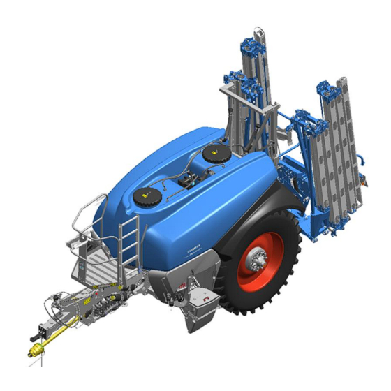
Layout and description LAYOUT AND DESCRIPTION Overview (1) Frame with trailer (7) Platform (2) Drawbar with traction loop (8) Pumps (3) Axle (9) Control centre (4) Wheels (10) Lift mast with pendulum system (5) Main tank (11) Boom (6) Clear water tank Chassis, general The chassis is part of the frame and carries the other assembly groups. -
Page 42: Suspension Systems
Layout and description 6.2.1 Suspension systems The following systems are used depending on the model: Without suspension System suspension Mechanical Pneumatic Without suspension The axle is adapted to the chassis with a rigid console. System suspension System suspension on the implement con- sists of: ... -
Page 43: Drawbar
Layout and description 6.2.2 Drawbar The drawbar (1) is the connection between the trailer (3) and the traction loop (3). The implement can be equipped with the following drawbars: upper connection (rigid and steerable) lower connection (rigid and steerable) ... -
Page 44: Axles
Layout and description Ø 50 mm, straight Ø 50 mm, angled K80 hitch ball coupling, straight K80 hitch ball coupling, angled Axles The implement axle is designed as a bra- king axle. -
Page 45: Deflector
Layout and description 6.3.1 Deflector The deflector (1) prevents the implement from damaging the crops to be sprayed. Braking system The implement can be fitted with any of these braking systems: Air brake system with manual controls Air brake system with automatic, load-dependent brake valve and air suspensi- ... - Page 46 Layout and description (4) Manual control (5) Double discharge valve Compressed air tank (7) Drain valve (8) Combo brake cylinder (9) Mounting The air brake system comprises the: Parking brake Service brake Rapid emergency brake...
- Page 47 Layout and description Depending on the actuation of the brake cylinders, the individual brake functions are activated. Parking brake The spring accumulators of the brake cyl- inder are activated or released with the red button (1) of the double discharge valve. The parking brake can only be activated or released if there is sufficient air in the compressed air reservoir.
-
Page 48: Air Brake System With Automatic, Load-Dependent Brake Valve And Air Suspension
Layout and description Rapid emergency brake If the brake lines are interrupted when the implement is disconnected from the tractor, emergency braking is automatically engaged, using the opera- ting pressure of the compressed air reservoir. 6.4.2 Air brake system with automatic, load-dependent brake valve and air suspension In the air brake system with automatic, load-dependent brake valve and air sus- pension, the braking pressure is set automatically by an automatic load-... -
Page 49: Hydraulic Braking System
Layout and description The implement is fitted with a level regula- tion system in order to maintain its height. The rod linkage (3) detects the height which is then adjusted by the valve (4). The air suspension (1) is supplied with air by means of: ... - Page 50 Layout and description When the tractor brake pedal is actuated, the hydraulic ram (2) extends. The hydrau- lic ram (2) pushes the brake lever (1) into the brake position. Service brake diagram, braked After braking, the tension spring (3) ret- racts the brake lever (1).
- Page 51 Layout and description By opening the brake valve (5), the preten- sioned compression spring (4) actuates the braking system via the hydraulic ram (2) and the brake lever (1). Parking brake, braked Activate parking brake: Pull the break away cable (6) manually. ...
-
Page 52: Fluid Circuit
Layout and description Fluid circuit Main tank Cleaning gun Agitator, bottom Edge moistening Agitator, top Agitator nozzle Injector, filling Canister rinsing jet Circulation return line ProFlow nozzle Internal cleaning Suction valve, manual Agitation selector valve, electric HighFlow valve, electric Suction connection External cleaning valve, electric Suction filter, agitation External cleaning... -
Page 53: Main Tank
Layout and description Main tank The main tank (1) is designed to hold wa- ter, sprays and fertilisers. The two tank openings (2) are provided for maintenance purposes. The ventilation system and the venting system (3) ensure the main tank is ventila- ted during spraying and vented during fil- ling. -
Page 54: Clear Water Tank
Layout and description Clear water tank The clear water tanks (1) are designed to hold clear water. The clear water is intended for: Internal cleaning Cleaning the main tank Cleaning the boom Cleaning the cans External cleaning The clear water tanks (1): ... -
Page 55: Hand Wash Canister
Layout and description Hand wash canister The hand wash canister (1) holds clean water. e.g. for hand washing. The level can be viewed from the platform (2). Step, platform Platform (1) with: ladder (2) for ascending holder (3) for transporting the filling hose The filling hose is used to suck spraying fluids from external tanks. -
Page 56: Pump
Layout and description The pressure filter (2) filters the volumetric flow to the nozzles on the pressure side. 6.11 Pump The implement comes complete with two pumps (1). The pump is designed to convey clear water, spraying fluids and liquid fertilisers. -
Page 57: Flush Valve
Layout and description The following components are located be- hind the induction tank (4): Pressure filter (5) Flush valve (6) Suction valve (6) Cleaning gun (7) Work lighting (9) 6.12.1 Flush valve The flush valve (1) is used for: ... -
Page 58: Chemical Inductor
Layout and description Draining the pressure filter: Pressure filter is not flushed. Spraying fluid is available at the outlet pipe. When the pump is switched off, the content of the pressure filter and the pipe system drains out of the pressure filter outlet pipe at normal pressure. - Page 59 Layout and description Tank (1) The tank can pivot into the operating po- sition or transport position. Screen (2) The screen (2) prevents dirt and pieces of spray chemical packaging from leaving the tank (1). Edge moistening (3) Edge moistening (3) assists with spray induction and cleans the tank (1).
-
Page 60: Connections
Layout and description Suction valve (1) The suction valve (1) is used to empty the chemical inductor tank by suction. Suction is continuously variable. 6.12.3 Connections The implement has the following connec- tions for filling and emptying: Filling the clean water tank (1) ... - Page 61 Layout and description Filling and draining (4) the hand-wash canister Connection for external cleaning using equipment supplied by the customer (5)
-
Page 62: Storage Compartment
Layout and description 6.13 Storage compartment Some items of personal protective equipment may only be carried on the implement if they are inside liquid-tight packaging. The storage compartment (1) is designed to carry small parts required for spraying. The storage compartment (1) is not liquid- or gas-tight. -
Page 63: Measuring Instruments
Layout and description 6.15 Measuring instruments 6.15.1 Flowmeter The flowmeter (1) measures the quantity of spray liquid flowing to the nozzles. The operating terminal displays the sprayed litres per minute (l/min). 6.15.2 Pressure gauge The pressure gauge is provided for monito- ring the spray pressure (automatic mode). -
Page 64: Spray Hydraulics Operating Terminal
Layout and description 6.17 Spray hydraulics operating terminal The spray hydraulics operating terminal (1) is used to set and control the main spray hydraulics functions. 6.17.1 Overview Function display (1) Start-up display: Display depends on function selected. Status display (2) Red display: function active Green display: function inactive ... -
Page 65: Menus And Functions
Layout and description 6.17.2 Menus and functions Main menu Menu level 1 Increase agitation intensity Spraying: Reduce agitation intensity Increase agitation intensity Agitation: Reduce agitation intensity Boom Cleaning: Internal cleaning of main tank Agitator and injector ... - Page 66 Layout and description Main menu Menu level 1 Pump Liquid sprays Suction from the suction connection Filling: Sprays to be dis- solved Suction from the clean water tank Suction from the main tank Pumping out:...
- Page 67 Layout and description Settings: Language Service menu Calibrate level indicator, Manual main tank: Automatic Agitators HighFlow, pumping out and pumping Information Press these buttons to select the main menus and functions. Press these buttons to: ...
-
Page 68: Operation Terminal
Layout and description 6.18 Operation terminal The LEMKEN CCI-50 operation terminal is used to operate the electronic control of the device The electronic control of the device is ope- rated with an operation terminal. All ISOBUS operation terminals can be used to operate the device. - Page 69 Layout and description (0) Arm 0 (3) Arm 3 (1) Arm 1 (4) Arm 4 (2) Arm 2 (5) Arm 5 The arm can be: height-adjusted tilted folded bent The user can work with a fully folded-out or partly folded boom.
-
Page 70: Boom Guide
Layout and description 6.19.1 Boom guide The height of the sprayer boom is adjusted via a hydraulic ram (1) on the lift mast. The boom is tilted by means of the hydrau- lic rams at the sides (2). The arms are bent using the internal hyd- raulic rams (3). -
Page 71: Nozzle Holders
Layout and description 6.19.3 Nozzle holders The nozzle holder (1) is provided for atta- ching (2) the nozzles. The user turns the nozzle holder (1) to sel- ect the nozzle for distribution. The same nozzles must be selected in all nozzle hol- ders. -
Page 72: Boom Lighting
Layout and description 6.19.5 Boom lighting Boom lighting (1) is intended to illuminate the spray pattern when working in the dark. -
Page 73: Preparations On The Tractor
Preparations on the tractor PREPARATIONS ON THE TRACTOR Overview The following preparations must be made before attaching the implement to the tractor: Check the tractor tyre pressure. Provide and check the necessary electronic connections. Provide and check the necessary hydraulic connections. ... -
Page 74: Check The Required Hydraulic Connections
Preparations on the tractor The tractor must have the sockets listed below to supply the electronic consumers on the implement: Consumer Volt Socket Lighting equipment DIN ISO 1724 Isobus socket ISO 11783 Alternatively: Power supply Isobus socket retrofit kit When installing the cables, ensure that they are protected from thermal and mechanical damage. -
Page 75: Installation Of The Operation Terminal
Preparations on the tractor Consumer EW/P Colour Height adjustment for drawbar P3/T3 Blue Electro-hydraulic operation Yel- constant current option 1 low/white Electro-hydraulic operation P6/T6 Yel- constant current option 2 low/white Electro-hydraulic operation Yel- constant current option 3 low/white Electro-hydraulic operation load sensing = single acting control device = pressure supply load sensing... -
Page 76: Mounting The Gyroscope
Preparations on the tractor 7.1.5 Mounting the gyroscope The gyroscope determines the angle speed of the tractor around the vertical axis of gyration (yawing angle speed). The accurate follow-on at the implement is cal- culated and controlled based on the mea- sured values supplied by the gyroscope, the driving speed and the angle values of the drawbar. - Page 77 Preparations on the tractor When the implement is intended for mounting on different tractors, the respec- tive gyroscope positions at the various tractors must be provided. To this end, up to three configurations can be generated in the control in which the different positions of the gyroscope are stored.
-
Page 78: Preparing The Implement
Preparing the implement PREPARING THE IMPLEMENT BEWARE On a new implement, the brakes have not been fully run-in at the factory. You should therefore bear in mind that the braking effect will be reduced on a new implement. Overview The following preparations must be carried out on the implement before it is atta- ched to the tractor: ... - Page 79 Preparing the implement Slowly and carefully, pull the tractor's trailer coupling up to approx. 10 cm a- way from the towing eye of the imple- ment. Secure the tractor to prevent it from rol- ling away. Connect the hydraulic connections for the drawbar height adjustment to the tractor.
- Page 80 Preparing the implement When coupling, ensure the towing eye of the implement is locked in place with the trailer coupling of the tractor. Relieve the stand of the implement. Lift the implement. To do so, use the tractor’s control de- vice to extend the drawbar cylinder.
-
Page 81: Implement With Air Brake System
Preparing the implement Open the shut-off valve in the LS sys- tem. Horizontally align the implement using the spool valve of the tractor. Close the shut-off valve (8). 8.2.1 Implement with air brake system Connect the brake couplings (1) of the device to the tractor. -
Page 82: Implement With Hydraulic Braking System
Preparing the implement 8.2.2 Implement with hydraulic braking system Bring the break-away valve to operating position. Connect the brake line to the tractor. Attach the break-away cable to a fixed component of the tractor. The length of the break-away cable must be shorter than the other hydraulic ho- ses attached to the tractor. -
Page 83: Conversion Of Device
Here, the following options apply: Allow the height of the towing eye im- plement to be adjusted by re-screwing. Have other traction loops approved by LEMKEN installed, see «Traction loops, page 203». ATTENTION: Only have towing devices approved by LEMKEN installed. -
Page 84: Setting The Oil Hydraulic System
Preparing the implement Setting the oil hydraulic system See the separate operating instructions for the electronic control system: Input menu Mounting and testing the drive shaft The end of the drive shaft which is marked with a tractor symbol must be mounted on the tractor. -
Page 85: Shortening The Drive Shaft
Preparing the implement 8.4.1 Shortening the drive shaft Pull the two halves of the drive shaft apart. Hold both halves of the drive shaft side- by-side at the shortest distance from the tractor. Mark the length which needs to be cut off on the outer protective tube. -
Page 86: Determining The Fill Volumes For The Implement
Preparing the implement Add the operating instructions which are attached to the drive shaft on delivery to these operating instructions. Ensure that the drive shaft protector is secured against rotation by attaching the chains (1) to a fixed point. Determining the fill volumes for the implement The following data and procedures must be used to determine the permissible fill volume for the implement [l/kg]:... - Page 87 Preparing the implement Enter the data from the implement’s type plate in the tables. Example table Data transfer- e.g. Data de- e.g. Data deter- e.g. red from the termined by mined by type plate weighing calculation Permissible Actual axle Permissible fill 3000 / 0.85 = gross weight of...
-
Page 88: Installation Of The Correct Nozzles
Preparing the implement For spraying fluids with a higher density, e.g. a 30% by weight UAN solution (= density factor 1.3 [kg/dm³]), the higher density must be taken into account by reducing the fill volume (e.g.: 1 l UAN / 1.3 = ~ 0.77 l/kg UAN → 3530 x 0.77 = ~ 2718 l UAN fill volume). - Page 89 Preparing the implement The nozzles are mounted on the nozzle holders with bayonet caps. It is recom- mended that a separate set of bayonet caps is used for each set of nozzles. Be aware that different bayonet caps must be used for each type of nozzle. ...
- Page 90 Preparing the implement Five-hole liquid fertilizer nozzles The five-hole nozzles are used in the following combination: Bayonet cap (1) Five-hole nozzle (2) Metering disc (3) Seal (4) Note the correct installation The arrow in the 2 following illustrations shows the direction of travel of the im- plement.
-
Page 91: Volumetric Metering
Preparing the implement Volumetric metering 8.7.1 General Volumetric metering is used to determine: Whether nozzles are worn, Which spray pressure on the pressure gauge corresponds to the actual spray pressure at the nozzle. Volumetric metering should be carried out on at least 3 nozzles from different sec- tions in order to establish an accurate output value for a nozzle. -
Page 92: Volumetric Measurement And Calibration
Preparing the implement Example: If the nozzle table states that the output from a nozzle should be 1.5 l/min at 2.5 bar and the measured value is only 1.2 l/min, the spray pressure should be increased until the specified individual nozzle output of 1.5 l is measured. ... -
Page 93: Driving On Public Highways
Driving on public highways DRIVING ON PUBLIC HIGHWAYS General information A proper lighting system, identification and equipment must be on the implement, if it is to be transported on public roads. The country-specific valid laws and regu- lations pertaining to driving on public roads must be observed. Hydraulic braking system Before driving on public roads: ... -
Page 94: Checking The Lighting Equipment
Driving on public highways 9.3.3 Checking the lighting equipment Activate the direction indicators in the tractor. If the tell-tale light for the direction in- dicator on the tractor (5) and the tell-tale light for the direction indicator on the im- plement (6) flash, the lighting equipment has been connected correctly. -
Page 95: Operation
Operation OPERATION 10.1 Prepare device for use 10.1.1 Adapt device for use Target: The external conditions and equipment of the device are appropriate for the intended use. Check the following before distribution and adjust if necessary: Check whether the unit contains anti- freeze. -
Page 96: Prepare The Device For Operation In Frosty Conditions
Operation 10.1.2 Prepare the device for operation in frosty conditions Risk of accident due to frozen braking system of the device WARNING If the braking system of the device is frozen, it is no longer possi- ble to brake the device. This may even be fatal or result in serious injuries. -
Page 97: Fill Device With Liquids
Operation 10.1.3 Fill device with liquids Target: All the necessary liquids are avail- able for use. Fill the following containers with liquids: Fill the handwash container with water, see "Filling the hand wash canister, pa- ge 97". For cleaning purposes on the fieldFill the clean water tank with water, see "Filling the clean water tanks, page 100". -
Page 98: Storage Compartment
Operation 10.2 Storage compartment The storage compartment is not gas- and liquid-tight. If you need to carry personal protective equipment in the storage compartment: The personal protective equipment must be inside gas- and li- quid-tight packaging. To open: Turn the handle (1) to the right and open the door. -
Page 99: Filling And Emptying The Hand Wash Canister
Operation 10.4 Filling and emptying the hand wash canister The contents of the hand wash canister are intended for cleaning purposes only WARNING Filling the hand wash canister with cleaning agent or spray chemi- cals may endanger the user or harm the environment. ... - Page 100 Operation Remove the blind cap (1). Fit a hose onto the connection (2). Open the clean water intake. Open the valve (3). Set the valve to the vertical position as shown. Fill the hand wash canister ...
-
Page 101: Emptying The Hand Wash Canister
Operation Pull and hold the pin (1). At the same time, fold the ladder (2) up. Release the pin (1). Ensure that the pin (1) engages pro- perly. 10.4.2 Emptying the hand wash canister Remove the blind cap (1). ... -
Page 102: Filling And Emptying The Clean Water Tanks
Operation 10.5 Filling and emptying the clean water tanks Risk of injury from cleaning agents or sprays Filling the clean water tanks with cleaning agents or spray chemi- WARNING cals may endanger the user or harm the environment. Only fill the clean water tanks with clean water. ... -
Page 103: Emptying The Clean Water Tanks
Operation To ensure that no water runs off the im- plement: Monitor filling of the clean water tanks on the level indicator (1). Stop filling in good time. After filling: Close the clean water intake. Remove the hose. ... - Page 104 Operation Press this button to select the Cleaning menu. Press this button to select the Clean Agi- tator and Injector menu. Press the rotary encoder (1) Turn the rotary encoder (1) to clean wa- ter tanks. ...
-
Page 105: Filling The Main Tank , General
Operation 10.6 Filling the main tank , general Prevent leakage and backflow of sprays When filling the main tank, no spray should leak out of the main DANGER tank into the environment or flow back into the filling pipe. Leaking or backflowing spray can harm the environment and af- fect human and animal health by polluting the drinking water sup- ply. -
Page 106: Filling Connection
Operation 10.7.1 Filling connection Place a container underneath the filling connection (2). Remove the blind cap (1). Fit a hose onto the filling connection (2). Fill the main tank. To ensure that no liquid overflows: Monitor filling of the main tank on the spray hydraulics operating terminal (1). -
Page 107: Suction Connection
Operation 10.7.2 Suction connection Before filling the main tank Pull and hold the pin (1). At the same time, fold the ladder (2) down. Release the pin (1). Climb the ladder (1) onto the platform (2). ... - Page 108 Operation Place a container underneath the suc- tion connection (2). Remove the blind cap (1). Fit the hose onto the suction connection (2). The valves for the induction control unit (1) must be closed. Lever (2) horizontal: valve open Lever (2) flipped vertically downwards: valve closed ...
- Page 109 Operation The options for filling the main tank are as follows: Pumping Setting for filling and agitation. With pump suction: the agitator pump draws in spraying fluid from an external source through the fil- ling hose and delivers it to the main tank via the agitators.
- Page 110 Operation Injector in conjunction with HighFlow. Setting for filling and more intensive agi- tation. Only with suction by the HighFlow injec- tor. The agitator pump draws in spraying flu- id from the main tank and returns it to the main tank via the agitators. The spraying pump draws in spraying fluid from the main tank and delivers it: ...
- Page 111 Operation Calculator (7), see «Calculator, page 111» Fill stop (3), see «Fill stop, page 113» To fill with the pumps: Press this button. To fill with HighFlow: Press this button. Switch on the pumps. Fill the main tank. To interrupt filling: ...
- Page 112 Operation Press this button. After an interruption in filling: Continue filling the main tank, or Agitate and spray the contents. After filling the main tank Agitate the contents of the main tank sufficiently according to the instructions for use of the spray.
- Page 113 Operation Place the suction hose securely in the holder (1). Pull and hold the pin (1). At the same time, fold the ladder (2) up. Release the pin (1). Ensure that the pin (1) engages pro- perly.
- Page 114 Operation When filling the main tank, the calculator can be used to calculate: (1) Spraying fluid [l] (water or fertiliser solution) (2) Spray [l] (preparation) Target values to be entered: (3) Spraying fluid per ha [l/ha] (4) Spray per ha [l/ha] (5) Area to be sprayed [ha] The calculator also calculates the area [ha] (5) that can be sprayed with the target va-...
- Page 115 Operation Press the rotary encoder (1). Turn the rotary encoder (1) to the area to be sprayed [ha] (4) and press to confirm your selection. 2. Result: The calculator uses the values entered to calculate the following requirements for the full area to be sprayed [ha] (4): (1) Spraying fluid [l] (water or fertiliser solution)
-
Page 116: Filling With Spray
Operation If the fill stop function is deactivated, the main tank can be filled beyond the values listed above. This may cause: Damage to the implement. Spray leakage. Monitor filling of the main tank on the operating terminal (1). ... - Page 117 Operation Pivoting the induction tank into the transport position Using the handle (1), fold the cover onto the induction tank. Press the locking device and holder (1) together and hold them. Pivot the induction tank upwards into the transport position.
- Page 118 Operation Reduce agitation intensity During and after filling of the main tank, the spray must be agitated according to the instructions for use of the spray. To increase the agitation intensity: Press this button. To reduce the agitation intensity: ...
- Page 119 Operation Remove the filling hose from the holder (1). Place a container underneath the suc- tion connection (2). Remove the blind cap (1). Fit the filling hose onto the suction connection (2). Filling Press this button to draw in spraying flu- id from the suction connection.
- Page 120 Operation The spraying pump draws in spraying fluid via the suction connection using a filling hose and delivers it: to the injector and to the induction control unit Pivot the induction tank into the opera- ting position. ...
- Page 121 Operation The suction valve (1) is used for conti- nuously variable suction of the induction tank contents into the main tank. (L) = suction valve closed (H) = suction valve open to maximum setting To prevent the induction tank from over- flowing: ...
- Page 122 Operation The canister rinsing jet is used to rinse empty spray canisters with clean water. The cleaning gun is used to clean larger canisters and the induction tank with clean water. The induction system is cleaned automati- cally as all the components are flushed with clean water during induction using clean water.
- Page 123 Operation To switch on the valve: Flip the lever (1) upwards (horizontal) to switch on the canister rinsing jet. Push the canister rinsing jet with canister downwards until it reaches the stop: An integral safety valve is opened. ...
- Page 124 Operation Clean more canisters. Empty the induction tank by suction Clean the induction tank with the cleaning gun. Then: Flip all the levers (1) down to switch off the valves. Close the suction valve. Pivot the induction tank into the transport position.
- Page 125 Operation Any liquid in the canister rinsing jet is sprayed if the canister rins- ing jet is pressed accidentally. Cover the canister rinsing jet with an empty canister or the meas- uring beaker. To switch on the valve: Flip the lever (1) upwards (horizontal) to switch on the canister rinsing jet.
- Page 126 Operation After cleaning: Flip the lever (1) down to switch off the cleaning gun. Close the suction valve. Place the cleaning gun (1) in the holder (2). Pivot the induction tank into the transport position. 2. Spraying fluid from the clean water tank ...
-
Page 127: Agitation
Operation 3. Spraying fluid from the main tank Fill the main tank with water or fertiliser solution according to the instructions for use of the spray. Press this button to draw in spraying flu- id from the main tank. ... - Page 128 Operation On the start-up display: Press this button. The menu is displayed. The agitation intensity of the implement can be set to 5 levels. The agitation intensity is shown on the dis- play (2): Level 1: minimum intensity ...
-
Page 129: Folding The Spray Boom
Operation 10.8 Folding the spray boom DANGER No people or animals in the folding zone Ensure that no people or animals are in the folding zone while the boom is being folded. See the separate operating instructions for the Megaspray electronic control sys- tem. -
Page 130: 10.10 Working With The Implement
Operation During the test run, check that all the components are working properly and are not leaking. To familiarise yourself with the individual functions: Operate all the implement functions, following these operating instructions. Also refer to the separate operating in- structions for the Megaspray electronic control system. - Page 131 Operation The level in the main tank is displayed on the operating terminal on the tractor or on the spray hydraulics operating terminal on the implement. Set the pendulum system. Set the implement and electronic control system to spraying. ...
-
Page 132: Spraying
Operation Carry out external cleaning. After the final spray run of the day or before interrupting spraying: Flush the implement with clean water. If the implement is not working properly: Identify the cause of the problem. Rectify the problem. 10.10.1 Spraying Spraying must not start until volumetric metering and calibration... - Page 133 Operation On the start-up display on the spray hyd- raulics operating terminal: Press this button. The menu is displayed. The agitation intensity is shown on the dis- play (1): Level 1: minimum intensity Level 5: maximum intensity To increase the agitation intensity: ...
-
Page 134: Working With The Boom Folded In On One Side
Operation 10.10.2 Working with the boom folded in on one side WARNING Risk of tipping for implements with a steering drawbar The implement may tip if the steering drawbar is actuated while the tractor is driving with the boom folded in on one side. ... -
Page 135: 10.11 End Nozzles
Operation When cleaning the boom, the agitator pump draws in spray and circulates it in a closed circuit. The spraying pump automatically draws in clean water from the clean water tank and sprays it via the nozzles. The spray circuit, including the nozzles, is flushed with clean water. -
Page 136: Switch Edge Nozzles
Operation The following edge nozzles are available: Edge nozzles with one-sided spray cone for sharp-edged treatment 10.11.1 Switch edge nozzles The edge nozzles are switched via the control unit: See the operating instructions for FieldTronic MegaSpray V02 Vega12. Edge nozzles are not taken into account in the calculations of the control system. - Page 137 Operation If the desired spray pattern is not achie- ved: Reposition the edge nozzles. Use other edge nozzles. Change the track.
-
Page 138: Cleaning
Cleaning CLEANING 11.1 Standard procedure Remaining quantities of spraying agent must not be drained off at the edges of the road or discharged into the sewer ATTENTION system. Where possible: Reuse collected spraying agent (after consul- ting the respective spraying agent manufacturer). ... -
Page 139: Emptying The Main Tank
Cleaning The following should be noted during the cleaning: Regulations of the spraying agent manu- facturer Regulations of the nozzle manufacturer These operating instructions Other regulations for handling spraying agents Standard procedure: Empty the main tank. ... -
Page 140: Pumping Remaining Quantities Out Of The Main Tank
Cleaning 11.2.2 Pumping remaining quantities out of the main tank Place a container under the pump-out connection (1). Remove the blind cap (2). Fit a hose onto the pump-out connection (1). Fit a hose to allow the content to be pumped out. -
Page 141: Draining Spraying Fluid Out Of The Main Tank
Cleaning To reduce the agitation intensity during pumping: Press this button. To increase the pumping speed:: Press this button. To reduce the pumping speed:: Press this button. Press this button to interrupt pumping. When pumping is complete: ... -
Page 142: Internal Cleaning
Cleaning Drain the contents of the main tank. After draining: Close the drain valve. Fit the blind cap (2). Check that the connection (1) is water- tight. Carry out internal cleaning. If necessary: Carry out external cleaning. 11.3 Internal cleaning 11.3.1... - Page 143 Cleaning Use the operating terminal to select and control: The source of the clean water The cleaning menu Press this button. The menu is displayed Display (2): Intake source Clean water tanks Main tank ...
-
Page 144: Cleaning The Boom When The Main Tank Is Empty
Cleaning For suction from an external source, fit a filling hose onto the suction connection (1). The suction hose is used to draw in clean water from an external container. 11.3.2 Cleaning the boom when the main tank is empty The main tank is filled with clean water for boom cleaning. - Page 145 Cleaning The menu is displayed. Press the rotary encoder (1). Turn the rotary encoder (1) to the intake source required: Clean water tank Suction connection Press the rotary encoder (1) to confirm. If the suction connection is selected: ...
-
Page 146: Internal Cleaning Of The Main Tank
Cleaning While driving on an untreated surface: Switch on the nozzles from the operating terminal. After 10 seconds, switch the nozzles off for 5 seconds then switch them back on. Continue spraying until the main tank is empty. - Page 147 Cleaning Press this button. The menu is displayed. Press the rotary encoder (1). Turn the rotary encoder (1) to the intake source (2) required: Clean water tank Suction connection Press the rotary encoder (1) to confirm. If the suction connection is selected: ...
- Page 148 Cleaning Cleaning cycle 1: Drive onto land that has not been spra- yed. Unfold the boom. Open the flush valve (1) slightly. (Lever (2) 1 cm above the stop (3)). Switch on the pumps. Operate the pumps for 1 minute at the nominal speed.
- Page 149 Cleaning If necessary: Add cleaning agent to the main tank. Follow the instructions for use of the cleaning agent. Operate the implement at this setting for at least 2 minutes. Press these buttons. The cleaning water: ...
- Page 150 Cleaning Clean water from the suction connection To ensure that the agitation system is also cleaned: Switch the agitators on. Press these buttons. If clean water is drawn in from an external source, the volume of water in the clean water tank is not relevant.
-
Page 151: Cleaning The Main Tank And Boom
Cleaning 11.3.4 Cleaning the main tank and boom This menu is used to clean the empty main tank and boom simultaneously. Clean water is drawn in by the agitator pump and the main pump. The agitator pump delivers the clean water to the main tank via the internal cleaning system. - Page 152 Cleaning Due to the high clean water requirement, we recommend that clean water should be drawn in via the suction connection. To ensure that the agitation system is also cleaned: Switch on the agitators. Press these buttons in sequence. ...
- Page 153 Cleaning Operate the implement at this setting for at least 2 minutes. Press this button. The menu is displayed. Press this button. The cleaning water: Is circulated by the agitator pump from the main tank, via the agitators and back to the main tank.
-
Page 154: Cleaning The Agitator And Injector System
Cleaning 11.3.5 Cleaning the agitator and injector system This menu is used to clean the agitator and injector system simultaneously. The agitator pump draws in clean water from the clean water tank and returns it to the main tank via the agitators. The spraying pump draws in spraying fluid from the main tank, clean water tank or an external source, depending on the intake source selected, and delivers it: ... - Page 155 Cleaning Press the rotary encoder (1) to confirm. If the suction connection is selected: Fit the filling hose onto the suction connection. Position the lever (2) 1 cm above the stop (3). Switch on the pump. ...
- Page 156 Cleaning The following assembly groups can be switched on or off using the valves in the induction control unit: (1) Canister rinsing jet and cleaning gun (2) Edge moistening (3) ProFlow nozzle (4) Agitator nozzle Using the handle (1), fold the cover onto the induction tank.
- Page 157 Cleaning Cleaning the canister rinsing jet: Place a measuring beaker or clean, empty canister over the canister rinsing jet. Push the canister rinsing jet with the measuring beaker or canister down- wards until it reaches the stop. Flip the lever (1) up (horizontal) to clean the canister rinsing jet (1) with clean wa- ter.
- Page 158 Cleaning Flip the lever (1) up (horizontal) to clean the cleaning gun (1) with clean water. Remove the cleaning gun from the hol- der. To switch on: Squeeze the handle (1). To switch off: Release the handle (1). Continuous operation: ...
- Page 159 Cleaning After cleaning: Place the cleaning gun (1) in the holder (2). To close the valve: Flip the lever (1) down. Remove the canister from the canister rinsing jet. Cleaning the edge moistening system and agitator nozzle To clean the edge moistening system (1) and agitator nozzle (2): ...
-
Page 160: External Cleaning
Cleaning After cleaning: Flip the lever (1) down to close the valve. 11.4 External cleaning Always use clean water for external cleaning. The cleaning water must not flow into surface water or drains. Cleaning must always take place on an unsealed, vegetated surface. - Page 161 Cleaning agent. External cleaning: Removes unwanted dirt and prevents accidental dripping / run-off of any adhering spray. Allows the external surface of the sprayer to be cleaned with a spray gun. During cleaning, always follow the: Spray manufacturer's instructions. ...
-
Page 162: Factory-Supplied External Cleaning System
Cleaning 11.4.1 Factory-supplied external cleaning system Press this button. Switch on the pump. Clean water is delivered to the cleaning gun (1). Remove the cleaning gun (1) from the holder (2). Pull the length of hose needed out of the hose reel (3). -
Page 163: Connection For Customer's Own External Cleaning System
Cleaning When external cleaning is complete: Pull the hose with the spray gun in jerks and release it immediately. The hose automatically winds onto the hose reel (3). Place the cleaning gun (1) in the holder (2). Connection for customer’s own external cleaning system 11.4.2 The maximum implement system pressure can be supplied to the... -
Page 164: Cleaning The Filters
Cleaning When external cleaning is complete: Switch off the pump. Select another spray hydraulics function. Press this button. Secure the external cleaning system on the implement. Remove the external cleaning system. Removing the external cleaning system: ... -
Page 165: Suction Filter
Cleaning Place a collector under the filters before cleaning. Regularly clean the suction filters (1) and the press filter (2). 11.5.2 Suction filter Remove the lock (1). A valve automatically closes the supply in the filter. ... -
Page 166: Press Filter
Cleaning When mounting, ensure the seal (4) is correctly inserted and not crushed. 11.5.3 Press filter To remove dirt particles from the system, we recommend to close the flush valve before the final spray for the day. Remove and clean the press filter after the last spray for the day. - Page 167 Cleaning To close the flush valve: Move the lever (1) to the stop position (2). Put the collector under the drain hose of the press filter. Unscrew the lock of the drain hose. To drain the spraying fluid from the press filter and the hydraulic hoses: ...
- Page 168 Cleaning Undo the cover (1). Remove the filter. Flush the filter housing with clear water to remove any contamination. Clean the individual components with water and a soft brush. Install press filter. When mounting, ensure the seal is cor- rectly inserted and not crushed.
-
Page 169: Uncoupling The Implement
Uncoupling the implement UNCOUPLING THE IMPLEMENT 12.1 Preparations Aim: The device is safely stored under- neath until the next use. Applications: After one use For wintering Preconditions: All tanks are empty. Implement is cleaned, see «Cleaning, page 136». -
Page 170: For Wintering
Uncoupling the implement Activate the parking brake of the tractor. Switch off the tractor engine. Remove the ignition key. Secure the tractor to prevent it from rol- ling away. 12.1.2 For wintering Aim: Ensure the implement is protected against frost damage. -
Page 171: Put Device Into Park Mode
Uncoupling the implement Provide biodegradable antifreeze. ATTENTION: Do not use liquid fertiliser. Liquid fertiliser will damage the rubber components. Observe the operating instructions and the safety data sheet of the antifreeze agent. All fluid-carrying parts: Drying ... -
Page 172: Unfold The Stands
Uncoupling the implement Take the wheel chock (2) from the hol- der (3). Secure the wheels of the implement against rolling away with the wheel chocks (2). Implement with hydraulic drawbar suspen- sion: Close shut-off valve (4) in the nitrogen accumulator. -
Page 173: Detaching The Implement
Uncoupling the implement Unfold the stand: Remove the peg (4). Remove pin (5). Lift the stand at the holder (6) and hold it. Swing the lock (7) away. Lift the stand with the holder (6) to the ground. - Page 174 Uncoupling the implement For hydraulic braking system: Release break away cable from the trac- tor. Attach the brake lines to the holders on the implement side. Uncouple the cardan shaft from the trac- tor. Attach the cardan shaft to the holder on the implement side.
-
Page 175: Put The Implement Out Of Operation
Put the implement out of operation PUT THE IMPLEMENT OUT OF OPERATION 13.1 Shutting down the implement in an emergency In an emergency shut down the implement via the tractor. Switch the tractor engine off. Remove the ignition key. Damage caused by improper storage of the implement If incorrectly or improperly stored, the implement may be dam- CAUTION... -
Page 176: Maintenance And Servicing
Maintenance and servicing MAINTENANCE AND SERVICING 14.1 Safely maintain the device Personnel For certain activities, e.g. braking system work, service personnel (e.g. in agricultural machinery workshops) are required. These activities are marked in the maintenance schedule. Preparations Switch off the device. ... -
Page 177: Environmental Protection
Maintenance and servicing During the maintenance and repair To prevent accidents and injuries: Wear protective equipment. Use the following instruments: Suitable tools Climbing aids Supporting elements Follow maintenance instructions For dismantling and mounting heavy com- ponents: ... -
Page 178: Maintenance Intervals
Maintenance and servicing 14.3 Maintenance intervals Interval Activity Hose connections Ropes Boom Bolted connections Oil filter hydraulics Hydraulic hoses Air filter, air brake system Pump Pressure accumulator, pump Axle Braking system 14.4 Oils and lubricants Amount per maintenance Assembly group Oil / lubricant interval Pump... -
Page 179: Lubricating
Maintenance and servicing Amount per maintenance Assembly group Oil / lubricant interval Cardan shaft Lithium-saponified As required grease, consistency class NL-G12. Surfaces OKS spray As required 14.5 Lubricating Eye injury due to grease When lubricating the lubrication points, grease can escape WARNING between components at high pressure and cause injury to the eyes. -
Page 180: Lubrication Schedule
Maintenance and servicing 14.5.2 Lubrication schedule The lubrication points are colour-coded. Position Number All 8 All 20 All 50 Before After the (see of lubri- the win- winter Operating hours Fig.) cation ter break break points 6 – 10... -
Page 181: Overview Of Lubricating Points
Maintenance and servicing 14.5.3 Overview of lubricating points Sliding tube (not shown) inside protection tube a) Grease nipples (d) of the ball coupling Joints (b) of the cardan shaft Contact area of the traction loop (c) Grease nipples (f) of the left- and right-side brake Grease nipples (e) of the steering cylinder levers... - Page 182 Maintenance and servicing Grease nipples (h) of the pulley Grease nipples (j) of the 3 rolls on the left and right side of the skid Rope (i) Grease nipples (k) of the hydraulic rams Grease nipples (l) of the deflection joints...
-
Page 183: Drive Shaft
Maintenance and servicing 14.6 Drive shaft Use lithium-lubricated grease, consistency class NL-G12. The drive shaft must be serviced on the tractor side and the implement side. Protective tube Safety chain Sliding tube not illustrated (inside the protective tube) Joints 14.6.1 Protective tube The protective tubes of the drive shaft must be checked for damage and wear. -
Page 184: Joints
Check hydraulic pipelines for damage and leaks. Replace damaged or faulty hydraulic ho- ses immediately. Check the manufacturing date of the hydraulic hoses. Replace after 6 years at the latest. Only use hydraulic hoses approved by LEMKEN. -
Page 185: Oil Filter In Electro-Hydraulic Operation
Maintenance and servicing 14.8 Oil filter in electro-hydraulic operation Dirty oil results in increased wear and damage to the implement’s ATTENTION hydraulic system. Replace the oil filter every year. Replace the oil filter as soon as the hydraulic system loses effi- ciency. -
Page 186: Venting The Compressed Air Tank
Maintenance and servicing 14.9.2 Venting the compressed air tank To activate the parking brake: Pull the red button of the park valve. Secure the implement with wheel chocks to prevent it from rolling away. Uncouple brake hose from the tractor. ... - Page 187 Maintenance and servicing The spring pressure of the air filter may cause the individual com- ponents of the air filter to fall to the ground in an uncontrolled manner. When dismantling the air filter, hold a collector under the air fil- ter.
-
Page 188: 14.10 Tightening Torques
Maintenance and servicing Connect the brake hoses to the tractor. Start the tractor engine. When the tractor engine is running, the braking system is automatically filled with compressed air. To release the parking brake: Press the red button of the park valve. ... -
Page 189: Bolts And Nuts Made Of Steel
Maintenance and servicing 14.10.2 Bolts and nuts made of steel Strength category Diameter 8.8 [Nm*] 10.9 [Nm*] 12.9 [Nm*] 13,6 16,3 23,4 32,9 39,6 M 10 46,2 64,8 77,8 M 12 80,0 M 14 M 16 M 20 M 24 1112 M 30 1314... -
Page 190: Wheel Nuts
Maintenance and servicing Diameter [Nm] M 22 M 24 M 27 14.10.4 Wheel nuts Maintenance intervals: After the first 8 operating hours After the first ride under load Every 50 operating hours The tightening torque for the wheel nuts (1) with centring locking bar (2) is 550 Nm. -
Page 191: 14.11 Check The Connections To The Tractor
Maintenance and servicing 14.11 Check the connections to the tractor 14.11.1 Hydraulic connections Risk of accidents due to escaping hydraulic fluid Hydraulic fluid which is ejected under high pressure (hydraulic oil) WARNING can penetrate the skin and cause serious injuries. In the event of injuries, consult a doctor immediately. -
Page 192: Pump
Maintenance and servicing 14.12 Pump 14.12.1 General information Requirement for pump operation: Sufficient oil Correct pressure at the pressure ac- cumulator Proper membranes Properly functioning valves Annual maintenance performed by a quali- fied and well-trained person: ... -
Page 193: Check Oil Level
Maintenance and servicing 14.12.2 Check oil level The oil level of the pump is checked at the sight glass during operation. WARNING: A cardan shaft drives the pump.Persons may be entangled, pulled in and seriously injured by the cardan shaft. ... -
Page 194: Refill Oil
Maintenance and servicing 14.12.3 Refill oil To refill with oil safely: Switch off the PTO shaft. The cardan shaft is stationary. Switch off tractor engine. WARNING: When the tractor engine is switched on, the PTO shaft can be en- gaged even though another person may have to refill the oil. -
Page 195: Replace Membranes
Maintenance and servicing 14.12.4 Replace membranes If the oil in the sight glass is discoloured white, this indicates damage to the pump membranes. In the event of white discoloration of the oil, stop spraying immediately. CAUTI- ON: Continuing to operate the pump will lead to it being damaged. -
Page 196: Check The Pressure At The Pressure Accumulator
Maintenance and servicing 14.12.5 Check the pressure at the pressure accumulator Check the pressure (1) at the pressure accumulator If the pressure measuring device of the instrument shows strong vibrations If the pressure hoses of the device vibrate strongly ... -
Page 197: 14.13 Sensor Calibration
Maintenance and servicing Alternative Fill the pressure accumulator (1) to ap- prox. 10 bar. Operate the pump at the specified speed. Observe the pressure hoses of the pump. If the pressure hoses vibrate, or the pressure of the pressure measuring sys- tem varies significantly, relieve thepres- sure using a filling device with a tyre in- flation valve. -
Page 198: 14.14 Filter
Maintenance and servicing 14.14 Filter Clean filters are a prerequisite for smooth operation. Therefore, the given filters must undergo regular maintenance. The use of pressure and nozzle filters with 80 meshes/inch or more may result in spraying agent being filtered out for some CAUTION spray agents. -
Page 199: Traction Loop And Hitch Ball Coupling
Maintenance and servicing 14.15.2 Traction loop and hitch ball coupling Have the following work carried out an- nually: Check for wear and, if necessary, re- place the traction loop and/or the hitch ball coupling 14.15.3 Braking system Have the following work carried out befo- re the start of the season: ... -
Page 200: 14.16 Control Connections
Maintenance and servicing 14.16 Control connections To check the implement as part of an offi- cial inspection, the implement is equipped with connections for test equipment. The connection points are marked with red union nuts or cable ties. Official equipment inspections may only be carried out by qualified and authorized persons. -
Page 201: Flowmeter
Maintenance and servicing 14.16.3 Flowmeter Connection (1) for measuring the flow 14.17 Information in case of faults and malfunctions Fault Reason Remedy Slow, continuous pressure Dirty pressure filter Clean the pressure increase with constant appli- filter cation quantity (l/ha) White colouring of the oil in Diaphragms defective Stop spraying imme- the pump... -
Page 202: Technical Data
Technical data TECHNICAL DATA 15.1 Dimensions Length (L) [mm] Width (W) [mm] Height (H) [mm] Minimum Maximum Minimum Maximum Minimum Maximum 5400 5900 2600 2800 3250 3600 5500 6000 2600 2700 3250 3600 5500 6000 2600 2700 3250 3600... -
Page 203: Weights
Technical data 15.2 Weights 15.2.1 Tare weight, maximum Vega 12 Axle load [kg] Drawbar load [kg] Gross weight [kg] 3000 4449 4900 4000 4540 5000 5000 4735 5215 Depending on the implement design, the actual weights differ from the values shown in the table. -
Page 204: Drawbar
Technical data If the load capacity of the wheels is lower than the stated axle loads, the per- missible axle load shall be reduced in accordance with the load capacity of the wheels, taking into account the permissible maximum speed. ... -
Page 205: With Internal Type Testing
Internal documentation number on: (1) Pivot joint (2) Drawbar (3) Tube 15.4 Traction loops Only LEMKEN-approved traction loops may be used. Traction loops must satisfy the following minimum technical requirements: Drawbar load [kg]: 2000 D-value [kN]: 56.32 Maximum speed [km/h]: 15.5... -
Page 206: Attachment And Trailer
The user can adjust the value of the limitation depending on exter- nal conditions, see operating instructions for FieldTronic MegaSpray V02 Vega 12. Model Track [mm] Tilt angle [°] Steering ang- Inner turning le [°]... -
Page 207: Tyres
Technical data Model Track [mm] Tilt angle [°] Steering ang- Inner turning le [°] radius [mm] Vega 4000 2100 16.1 39** 4983 Vega 5000 1500 18031 Vega 5000 1800 8363 Vega 5000 1800 13.1 34** 6091 Vega 5000 2100 16.7 6659 Vega 5000 2100... -
Page 208: Use Of Own Wheels Or Wheels Which Are Not Listed In The List Of Wheels
Technical data Designation Width [mm] [mm] [mm] [kg] [bar] 460/85 R42 (18.4 R42) 5532 5800 4.50 480/80 R46 5782 4250 2.40 520/85 R38 5547 5800 3.60 520/85 R42 (20.8 R42) 5780 5640 2.80 520/85 R42 (20.8 R42) 5780 5640 2.80 520/85 R46 6114 6500... -
Page 209: Rims
Technical data wheels must be examined by an expert. In case of critical driving conditions, the technical data of the implement must be modified and the filling quantity (kg) and/or the maximum permissible speed must be reduced. If a certificate is provided for the implement, only the wheels listed in the certifi- cate may be used. -
Page 210: 15.10 Track Width
Ø of the bolt circle for wheel bolts [mm] ET +6 E.g. offset of the rim [mm]: +6/-21 ET -21 15.10 Track width 15.10.1 Vega 12/3000 1500 mm and up With follow-on control for 1800 mm and up Maximum Maximum Flange dimension... -
Page 211: Vega 12/4000 And 5000
[mm] [mm] 1607 1500 1750 1907 1800 2050 2207 2100 2350 15.10.2 Vega 12/4000 and 5000 1800 mm and up Maximum Maximum Flange dimension Track [mm] Track [mm] tyre width tyre width of the axle [mm] ET +6 ET -21... -
Page 212: 15.11 Drive Shaft
Technical data Maximum Maximum Flange dimension Track [mm] Track [mm] tyre width tyre width of the axle [mm] ET +56 ET -71 [mm] [mm] 1907 1800 2050 2207 2100 2350 15.11 Drive shaft Version Connection To tractor To implement 1 ⅜ (6) 1 ⅜... -
Page 213: 15.12 Pumps
Technical data 15.12 Pumps Type P 200/P200 P 260/P260 Power take-off DIN 9611 / ISO 500 Design Piston diaphragm pump Number of pistons 2 x 4 Connection Hose Min. internal diam., suction side [mm] Min. internal diam., pressure side 31.50 31.00 [mm]... -
Page 214: 15.13 Spray Fluid System
Technical data Type P 200/P200 P 260/P260 Diaphragm material Rubber Number of pressure accumulators 15.13 Spray fluid system 1.0 – 8.0 Spray pressure range of the implement for water [bar]: Permissible system pressure [bar]: Distribution rate depending on pump, nozzles and driving speed [l/ha]: 200 –... - Page 215 Technical data Pump-off connection: 2“ Kamlok coupling Filling connection, performance Maximum filling quantity [l/min]: Maximum filling pressure [bar]: Intake connection, performance With / without Highflow and Highflow injector, filling Maximum negative pressure [bar]: - 0.3 - 0.8 Maximum suction depth [m]: 2“...
-
Page 216: Boom
Technical data 15.14 Boom 15… 30 m Width depending on version 7… 11 Number of arms depending on version Number of possible sections Distance between the nozzles 50 cm Approx. operating pressure 10 bar Maximum nozzle distance to the floor approx. 1.50 m (with implement parked) Pivoting range... -
Page 217: Number Of Nozzles And Sections
Technical data Width of arms [m] Number Boom Width [m] of arms RA 30/24 15.14.3 Number of nozzles and sections Depending on the boom, the following sections combination is saved to the control as sections configuration 1. Boom Number of nozzles Number of sections Configuration RA 15/12... -
Page 218: 15.16 Oil Hydraulics
Check the manufacturing date of the hydraulic hoses. Replace after 6 years at the latest. Only use hydraulic hoses approved by LEMKEN. 15.16 Oil hydraulics Pressure required in the tractor hydraulic system for implement cy- linders in the oil hydraulic system [bar]:... -
Page 219: 15.18 Filter
Technical data 15.18 Filter Diameter Length/ Screen Mesh [mm] depth area width [mm] [cm²] [mm] Standard Suction filter 22500 0.36 Pressure filter 80 mesh (yel- 0.177 low) Optional equipment/accessories Filter on the filling hose 32987 1.00 Pressure filter 50 mesh 0.297 (blue) Pressure filter 100 mesh... -
Page 220: Appendix
Appendix APPENDIX 16.1 General information about nozzles Each nozzle type has a different volume flow, spray pattern, drop size and nozzle characteristics. The liquid to be sprayed, the environmental conditions, the nozzle characteristics and official regulations such as distance conditions, drift reduction classes etc. -
Page 221: Nozzle Tables
Appendix Spray height Optimum Pressure Optimum Spray above Designation Material (1) spray height Size (2) range spray pres- angle target area (cm) (bar) sure (bar) (cm) AGROTOP TD-HiSpeed Cer. 110° 40 - 60 .015 -. 05 2 - 10 4 - 8 Liquid fertiliser nozzles LECHLER FD 130º... -
Page 222: Nozzle Sizes 06 - 10
Appendix Nozzle spacing: 50 cm l/ha Flow 100 125 175 200 225 250 300 350 400 500 l/min 30.0 24.0 20.0 17.1 15.0 13.3 12.0 10.0 8.6 6.0 2.50 31.2 25.0 20.8 17.8 15.6 13.9 12.5 10.4 8.9 6.2 2.60 32.4 25.9 21.6 18.5 16.2 14.4 13.0 10.8 9.3 6.5 2.70... -
Page 223: Dosage Tables For Liquid Fertilisers
Appendix For conversion: Volume flow of water Correction fac- actual volume flow of (value on the basis of wa- the spraying liquid ter with density 1.0) After calculation of the actual volume flow of the spraying liquid, adjustment of im- plement and the output of the individual nozzles can be obtained from the dosage table. - Page 224 Appendix Meter- l/min L UAN (*)/ha washer 10.0 11.0 12.0 14.0 16.0 18.0 Ø km/h km/h km/h km/h km/h km/h km/h km/h km/h km/h km/h 14.5 mm 0.46 0.41 0.65 0.57 0.80 0.70 0.92 0.81 1.03 0.91 1.0 / 39 1.13 1.00 1.22...
-
Page 225: Dosage Table - Sj-7 Liquid Fertiliser Nozzle
Appendix Dosage table – SJ-7 liquid fertiliser nozzle 16.5.2 Water [l/ha] at 50 cm nozzle spacing Nozzle Pressure [l/min] [km/h] (Colour) [bar] nozzle 0.39 78.0 58.5 46.8 39.0 29.3 23.4 (Dark green) 0.46 92.0 69.0 55.2 46.0 34.5 27.6 0.52 78.0 62.4 52.0... - Page 226 Appendix Water [l/ha] at 50 cm nozzle spacing Nozzle Pressure [l/min] [km/h] (Colour) [bar] nozzle 1.77 (Grey) 2.01 2.19 2.35 2.61 2.28 (White) 2.66 2.94 3.15 3.46 1038 2.84 (Light blue) 3.32 3.67 1101 3.94 1182 4.33 1299 4.09 1227 (Light green) 4.82 1446...
-
Page 227: Dosage Table, Five-Hole Nozzle Fl
Appendix 16.5.3 Dosage table, five-hole nozzle FL Nozzle Permissible metering washer 0.8/1.0/1.2 mm Ø POM (black) 1.2/1.5/1.8 mm Ø POM (grey) Nozzle caps required SW 10 Metering washer diameter 15 mm [l/min] UAN [l/ha] Metering Pres- washer sure [km/h] H²O Ø/mm [bar] 0.31... -
Page 228: Uan Dosage Table (28/1.28 Kg/L) For Nozzles Id, Idn, Idk, Idkn And Fd
Appendix The distribution rates indicated apply to UAN (28/1.28 kg/l). A conversion factor must be applied to liquid fertilisers with a different density. For accurate dosing, volumetric metering is recommended on first use and an- nually thereafter. 16.5.4 UAN dosage table (28/1.28 kg/l) for nozzles ID, IDN, IDK, IDKN and l/min UAN l/ha Pres-... - Page 229 Appendix l/min UAN l/ha Pres- Nozzle (Co- sure km/h lour) [bar] 0.91 0.80 (Red) 1.12 0.99 1.29 1.14 1.44 1.27 1.58 1.39 1.82 1.60 1.14 1.00 (Brown) 1.39 1.22 1.61 1.42 1.80 1.58 1.97 1.73 2.28 2.01 1.67 1.47 (Grey) 1.93 1.70 2.16...
- Page 230 Appendix l/min UAN l/ha Pres- Nozzle (Co- sure km/h lour) [bar] 4.24 3.73 (Light 4.90 4.31 1035 green) 5.48 4.82 1157 6.00 5.28 1267 1056 6.93 6.10 1463 1220 1045 5.66 4.98 1195 (Black) 6.53 5.75 1379 1149 7.30 6.42 1542 1285 1101...
-
Page 231: Dosage Table, Liquid Fertiliser Nozzle Fd
Appendix 16.5.5 Dosage table, liquid fertiliser nozzle FD l/min UAN l/ha Nozzle Pressure km/h (Colour) [bar] 0.85 0.75 (Dark blue) 0.98 0.86 1.20 1.06 1.39 1.22 1.13 1.00 (Red) 1.31 1.15 1.60 1.41 1.85 1.63 1.41 1.24 (Brown) 1.63 1.44 2.00 1.76 2.31... - Page 232 Appendix l/min UAN l/ha Nozzle Pressure km/h (Colour) [bar] 5.66 4.98 (Black) 6.53 5.75 1149 8.00 7.04 1408 1056 9.24 8.13 1626 1220 Notes: The table relates to a nozzle spacing of 50 cm and l/ha values based on a UAN solution (28/1.28 kg/l).
-
Page 233: Dosage Table, Six-Hole Nozzle Esi
Appendix 16.5.6 Dosage table, six-hole nozzle ESI UAN l/ha Pres- Nozzle (Co- km/h sure l/min lour) [bar] -015 (Green) 0.30 0.37 0.43 0.48 0.53 0.56 0.61 -02 (Yellow) 0.41 0.50 0.57 0.64 0.70 0.76 0.80 -03 (Blue) 0.61 0.75 0.86 0.96 1.06 1.14... - Page 234 Appendix UAN l/ha Pres- Nozzle (Co- km/h sure l/min lour) [bar] 1.52 1.63 1.01 (Brown) 1.24 1.44 1.60 1.76 1.90 2.02 1.22 (Grey) 1.49 1.72 1.92 2.11 2.28 2.43 Notes: The values in the table apply to UAN liquid fertiliser at 1.30 kg/l and 10°C. ...
-
Page 235: Technical Remaining Quantities
Appendix 16.6 Technical remaining quantities Remaining quantity [l] Slope Level ground Contour line Vega 12 3000 4000 5000 16.7 Displays, spray hydraulics The following functions can be displayed with the spray hydraulics operating ter- minal: Spraying selector valve Agitation selector valve ... - Page 236 Appendix Induction, main tank External cleaning Cleaning, boom Cleaning, agitator and injector Cleaning program Filling, clean water Manual switching Set to safe state Cleaning, main tank and boom Cleaning, boom and agitator ...
-
Page 237: Valve Positions
Appendix 16.8 Valve positions (C) = Circulation (S) = Spraying Circulation valve: (I) = Induction (F) = Filling HighFlow valve: Stop button Agitation selector valve Agitation control valve Agitation valve, bottom Agitation valve, top Internal cleaning valve Spraying selector valve Spraying control valve Injector valve... - Page 238 Appendix Spraying menu: Nozzles with operating terminal switched off Agitation selector valve Agitation control valve Agitation valve, bottom Agitation valve, top Internal cleaning valve Spraying selector valve Spraying control valve Injector valve External cleaning valve Spraying valve Pump-out valve Bypass valve Circulation valve Single-nozzle valve...
- Page 239 Appendix Spraying menu: Nozzles with operating terminal switched on Agitation selector valve Agitation control valve Agitation valve, bottom Agitation valve, top Internal cleaning valve Spraying selector valve Spraying control valve Injector valve External cleaning valve Spraying valve Pump-out valve Bypass valve Circulation valve Single-nozzle valve...
- Page 240 Appendix Agitation menu Agitation selector valve Agitation control valve Agitation valve, bottom Agitation valve, top Internal cleaning valve Spraying selector valve Spraying control valve Injector valve External cleaning valve Spraying valve Pump-out valve Bypass valve Circulation valve Single-nozzle valve HighFlow valve Depending on the implement operating terminal setting After setting the agitation intensity;...
- Page 241 Appendix Cleaning menu: Clean the boom Nozzles with operating terminal switched off Agitation selector valve Agitation control valve Agitation valve, bottom Agitation valve, top Internal cleaning valve Spraying selector valve (source-dependent) Spraying control valve Injector valve External cleaning valve Spraying valve Pump-out valve Bypass valve...
- Page 242 Appendix Cleaning menu: Clean the boom Nozzles with operating terminal switched on Agitation selector valve Agitation control valve Agitation valve, bottom Agitation valve, top Internal cleaning valve Spraying selector valve (source-dependent) Spraying control valve Injector valve External cleaning valve Spraying valve Pump-out valve Bypass valve...
- Page 243 Appendix Cleaning menu: Internal cleaning of main tank Agitation selector valve (source-dependent) Agitation control valve Agitation valve, bottom Agitation valve, top Internal cleaning valve Spraying selector valve Spraying control valve Injector valve External cleaning valve Spraying valve Pump-out valve Bypass valve Circulation valve Single-nozzle valve...
- Page 244 Appendix Cleaning menu: Clean the boom and internal cleaning of main tank Nozzles with operating terminal switched off Agitation selector valve (source-dependent) Agitation control valve Agitation valve, bottom Agitation valve, top Internal cleaning valve Spraying selector valve (source-dependent) Spraying control valve Injector valve External cleaning valve Spraying valve...
- Page 245 Appendix Cleaning menu: Clean the boom and internal cleaning of main tank Nozzles with operating terminal switched on Agitation selector valve (source-dependent) Agitation control valve Agitation valve, bottom Agitation valve, top Internal cleaning valve Spraying selector valve (source-dependent) Spraying control valve Injector valve External cleaning valve Spraying valve...
- Page 246 Appendix Cleaning menu: Agitators and injector Agitation selector valve Agitation control valve Agitation valve, bottom Agitation valve, top Internal cleaning valve Spraying selector valve (source-dependent) Spraying control valve Injector valve External cleaning valve Spraying valve Pump-out valve Bypass valve Circulation valve Single-nozzle valve HighFlow valve...
- Page 247 Appendix Cleaning menu: External cleaning Agitation selector valve Agitation control valve Agitation valve, bottom Agitation valve, top Internal cleaning valve Spraying selector valve Spraying control valve Injector valve External cleaning valve Spraying valve Pump-out valve Bypass valve Circulation valve Single-nozzle valve HighFlow valve...
- Page 248 Appendix Fill Spray menu: Injector Agitation selector valve Agitation control valve Agitation valve, bottom Agitation valve, top Internal cleaning valve Spraying selector valve Spraying control valve Injector valve External cleaning valve Spraying valve Pump-out valve Bypass valve Circulation valve Single-nozzle valve HighFlow valve Depending on the implement operating terminal setting, <...
- Page 249 Appendix Fill Spray menu: HighFlow Agitation selector valve Agitation control valve Agitation valve, bottom Agitation valve, top Internal cleaning valve Spraying selector valve Spraying control valve Injector valve External cleaning valve Spraying valve Pump-out valve Bypass valve Circulation valve Single-nozzle valve HighFlow valve (I) (1)
- Page 250 Appendix Fill Spray menu: Pump Agitation selector valve Agitation control valve Agitation valve, bottom Agitation valve, top Internal cleaning valve Spraying selector valve Spraying control valve Injector valve External cleaning valve Spraying valve Pump-out valve Bypass valve Circulation valve Single-nozzle valve HighFlow valve When main tank is full...
- Page 251 Appendix Fill Spray menu: Spraying fluid intake from external source Agitation selector valve Agitation control valve Agitation valve, bottom Agitation valve, top Internal cleaning valve Spraying selector valve Spraying control valve Injector valve External cleaning valve Spraying valve Pump-out valve Bypass valve Circulation valve Single-nozzle valve...
- Page 252 Appendix Fill Spray menu: Spraying fluid intake from clean water tank Agitation selector valve Agitation control valve Agitation valve, bottom Agitation valve, top Internal cleaning valve Spraying selector valve Spraying control valve Injector valve External cleaning valve Spraying valve Pump-out valve Bypass valve Circulation valve...
- Page 253 Appendix Fill Spray menu: Spraying fluid intake from main tank Agitation selector valve Agitation control valve Agitation valve, bottom Agitation valve, top Internal cleaning valve Spraying selector valve Spraying control valve Injector valve External cleaning valve Spraying valve Pump-out valve Bypass valve Circulation valve Single-nozzle valve...
- Page 254 Appendix Pump-out menu: Pump out spraying fluid into an external container Agitation selector valve Agitation control valve Agitation valve, bottom Agitation valve, top Internal cleaning valve Spraying selector valve Spraying control valve Injector valve External cleaning valve Spraying valve Pump-out valve Bypass valve Circulation valve...
-
Page 255: Index
Index INDEX Airborne sound ....................217 Brakes ......................... 76 Check hydraulic hoses ................182, 215 Determining the fill volumes for the implement ............ 84 Drain antifreeze agent ..................95 Electronic connections ..................71 External cleaning ....................158 Filling and emptying the clean water tank ............100 Gyroscope ......................
Need help?
Do you have a question about the Vega 12 and is the answer not in the manual?
Questions and answers