Table of Contents

Subscribe to Our Youtube Channel
Related Manuals for LEMKEN Albatros 10


Summary of Contents for LEMKEN Albatros 10
- Page 1 Operating Instructions Trailed Field Sprayer Albatros 10 - en - Item no. 17513188 02/11.18 LEMKEN GmbH & Co. KG Weseler Straße 5, 46519 Alpen / Germany Telephone +49 28 02 81 0, Fax +49 28 02 81 220 lemken@lemken.com, www.LEMKEN.com...
- Page 3 However, this brief instruction is not a substitute for thorough study of the operating instructions. These operating instructions will help to familiarise you with the LEMKEN GmbH & Co. KG device and the options available for using it.
- Page 4 Remember that you should only use genuine LEMKEN spare parts. Reproduction parts have a negative influence on the function of the device, have a shorter ser- vice life and present risks and hazards that cannot be estimated by LEMKEN GmbH & Co. KG. They also increase the maintenance costs.
-
Page 5: Table Of Contents
CONTENTS General information ....................13 Liability ......................... 13 Guarantee ........................13 Copyright ........................14 Optional accessories ....................14 Type plate ........................15 Symbols used in the Operating Instructions ............17 Hazard classes ......................17 Information........................17 Environmental protection ................... 17 Indication of passages .................... - Page 6 Operation on public highways ................... 28 3.8.1 Lighting system and identification ................28 3.8.2 Permissible weight of the implement ................. 28 3.8.3 Requirements of the tractor ..................29 3.8.4 Check before departure ..................... 29 3.8.5 Correct behaviour in road traffic ................32 Obligation of the operator ..................
- Page 7 Liquid flow ........................55 5.5.1 Overview ........................55 5.5.2 Description of the spraying process ................56 5.5.3 Liquid flow to nozzles....................57 Main tank ........................58 Clean water tank ......................60 Water canister for hand washing ................60 Filter ..........................61 5.10 Pumps ..........................
- Page 8 5.22 Boom ..........................72 5.22.1 Part-width section valves ..................73 5.22.2 Single nozzle valves ....................73 5.22.3 Nozzle holders ......................73 5.22.4 Nozzles ........................74 5.22.5 Spacer ........................74 5.22.6 Spray cone lighting ....................74 5.23 Drag hose ........................75 Preparations ......................
- Page 9 Operation ......................... 99 Prepare device for use ....................99 7.1.1 Adapt device for use ....................99 7.1.2 Prepare the device for operation in frosty conditions ..........100 7.1.3 Fill device with liquids ....................101 7.1.4 Drain antifreeze agent ..................... 101 Filling and emptying the water canister for hand washing ........
- Page 10 7.15 Working with drop hoses ..................130 7.15.1 Attaching drop hoses .................... 130 7.15.2 Spraying with drop hoses ..................131 7.16 Fold in sprayer boom ....................132 7.16.1 Standard procedure ....................132 7.17 System cleaning with partially filled main container ..........133 7.17.1 Flush the pipe system before interruption ............
- Page 11 10 Maintenance and servicing .................. 159 10.1 Safely maintain the device..................159 10.1 Environmental protection ..................160 10.2 Maintenance intervals ....................161 10.3 Oils and lubricants ....................162 10.4 Lubricating ......................... 163 10.4.1 Additional care once the season is over ............... 163 10.4.2 Traction loop ......................
- Page 12 10.8 Air brake ........................178 10.8.1 General ........................ 178 10.8.2 Bleeding ....................... 178 10.8.3 Cleaning ....................... 179 10.9 Tightening torques ....................180 10.9.1 General ........................ 180 10.9.2 Bolts and nuts made of steel ................181 10.9.3 Bolts and nuts made of V2A ................. 181 10.9.4 Wheel nuts ......................
- Page 13 11.2 Weight ........................192 11.2.1 Tare weight......................192 11.2.2 Permissible weight ....................192 11.2.3 Load data of the implement depending on the permissible wheels ...... 193 11.3 Drawbar ........................194 11.4 Connecting fixture and drawbar extension ............. 194 11.5 Traction loops ......................195 11.6 Axles ...........................
- Page 14 11.18.4 B33 ........................207 11.18.5 B36 ........................208 11.18.6 B39 ........................208 11.19 Noise, airborne sound ....................208 12 Appendix ........................ 209 12.1 General information about nozzles ................209 12.2 Nozzle field of application ..................209 12.3 Nozzle tables......................210 12.3.1 Nozzle sizes 01 - 05 .....................
-
Page 15: General Information
Co. KG, in particular Section IX, shall apply. Liability. In line with the dimensions cited in these conditions the LEMKEN GmbH & Co. KG shall not be held liable for any personal or material damage, when such damage is caused by one or more of the following reasons: ... -
Page 16: Copyright
Infringements will result in a claim for damages. Optional accessories LEMKEN implements may be equipped with various accessories. The operating instructions below describe both series components and optional accessories. Please note: These accessories will vary depending on the type of equipment. -
Page 17: Type Plate
General information Type plate The implement carries a type plate. The type plate can be found at front right on the implement. The operating instructions may apply to different implement types or variants of the implement. The operating instructions indicate infor- mation which only applies to a specific im- plement type or a specific variant of the implement. - Page 18 General information 1 Series 2 Type designation 3 Serial number 4 Year of manufacture 5 Permissible drawbar load [kg] 6 Permissible axle load [kg] 7 Permissible gross weight [kg] 8 Company logo and address 9 CE marking (only within the European Union) 10 Name of manufacturer 11 Type, variant, version 12 Type approval date...
-
Page 19: Symbols Used In The Operating Instructions
Symbols used in the Operating Instructions SYMBOLS USED IN THE OPERATING INSTRUCTIONS Hazard classes The following symbols are used in the Operating Instructions for particularly im- portant information: DANGER Denotes an imminent hazard with high risk, which will result in death or severe physical injury, if not avoided. -
Page 20: Indication Of Passages
Symbols used in the Operating Instructions Indication of passages The following symbols are used for particular passages in the operating instruc- tions: Indicates work steps Indicates enumerations... -
Page 21: Safety Measures And Precautions
Safety measures and precautions SAFETY MEASURES AND PRECAUTIONS General safety instructions for the operator are specified in the chapter entitled «Safety measures and precautions». At the start of some main chapters the safety instructions, which refer to all work to be carried out in this chapter, are listed to- gether. -
Page 22: Safety And Warning Signs
Safety measures and precautions Clarify questions of comprehension concerning the contents of these operating instructions before starting work. To do this, contact the LEMKEN sales partner if required. Safety and warning signs 3.3.1 General information The implement features all equipment which ensures safe operation. -
Page 23: Meaning Of Other Symbols
Safety measures and precautions Before carrying out maintenance or repair work, switch off the engine and remove key. Do not remain in the operating and swivel area of the implement. Danger of crushing. Keep a sufficient distance away from elec- tric high-voltage lines. - Page 24 Safety measures and precautions Lashing points Sling points Test certificate Operating the parking brake (hydraulic braking system) Connection overview of hydraulic hoses The label includes: the data for implement inspections the maximum weights of the implement when empty and filled...
-
Page 25: Special Safety Instructions
Safety measures and precautions Special safety instructions Risk of injury due to non-observance of the currently valid occupational safety guidelines If the currently valid occupational safety guidelines are bypassed WARNING or safety equipment is rendered unusable when handling the de- vice, there is a risk of injury. -
Page 26: Danger Areas
Safety measures and precautions Risk of injury when freeing casualties When rescuing people trapped or injured by the implement, there is a risk of additional serious injury to the casualty if the hydraulic connections were not connected according to their colour coding as described in the section entitled “Required hydraulic equip- ment”. - Page 27 Safety measures and precautions Moving danger areas - spraying liquid There is a danger of injury to the operator and nearby persons and animals due to contact with spraying liquids and liquid fertiliz- ers as well as from inhaling spraying agents and liquid fertilizers. In addition, there is also a danger to the environment due to incor- WARNING rect handling and use of spraying agents.
-
Page 28: Danger Areas When Operating The Implement
Safety measures and precautions 3.5.1 Danger areas when operating the implement 19 m – 43 m 3.5.2 Danger area when folding in and out 19 m – 43 m... -
Page 29: Residual Risks
Safety measures and precautions Risk of injury through contact with and inhalation of pesti- cide and liquid fertiliser WARNING There is a risk of poisoning or pollution contact with or inhaling of pesticides and liquid fertiliser for anyone in the implement's dan- ger zone as well as for the environment. -
Page 30: Applicable Rules And Regulations
Safety measures and precautions Applicable Rules and Regulations The following section lists the specific national regulations which must be ob- served during operation of the implement: the highway code. the health and safety laws and regulations. the laws and regulations for operational safety. ... -
Page 31: Requirements Of The Tractor
Safety measures and precautions The maximum permissible speed is determined by the applicable regulations specific to the country and the wheels which are used. 3.8.3 Requirements of the tractor The tractor must have a suitable drawbar coupling for the implement. ... - Page 32 Safety measures and precautions Implement with compressed air brakes and brake force regulator: Use the lever to adjust the braking force to the level of the implement. Implement with hydraulic braking sys- tem: Release the parking brake. To do so, move the lever (1) into transport posi- tion.
- Page 33 Safety measures and precautions Lock the control unit against uninten- tional operation. Before departure, check the area in the vicinity of the implement. No persons may be present in the vicini- ty of the implement. Risk of accidents due to inadequate braking deceleration In the event of insufficient braking deceleration, the combination of tractor and implement will be unable to be braked or not be braked quickly enough.
-
Page 34: Correct Behaviour In Road Traffic
Safety measures and precautions 3.8.5 Correct behaviour in road traffic When driving on public highways, observe the relevant statutory national regu- lations. Driving behaviour, steering and braking performance are influenced by ballast weights. Ensure that the tractor has adequate steering and braking perfor- mance. -
Page 35: Centring Of The Steering Drawbar In The Middle Setting
Safety measures and precautions Operate the device only in compliance with all connection and default values provided by the manufacturer! Use original spare parts only! 3.10 Centring of the steering drawbar in the middle setting DANGER The implement must be brought into the middle setting and the control deactivated before driving on roads. -
Page 36: Manual Drawbar Steering
Safety measures and precautions 3.10.1 Manual drawbar steering Bring the implement to the middle posi- tion with the tractor control unit before driving on roads. The middle position has been achieved if the two markings (1) are opposite to each other. -
Page 37: Safe Operation Of The Implement
Safety measures and precautions 3.11 Safe operation of the implement 3.11.1 General Before starting work, familiarise yourself with all the equipment and control ele- ments, as well as their function. Only start the implement if all the safety devices are attached and are in their safe positions. -
Page 38: Hydraulic System
Safety measures and precautions 3.11.3 Hydraulic system The hydraulic system is under high pressure. When connecting hydraulic cylinders and motors, ensure that the specified hy- draulic hose connection is used. When connecting the hydraulic hoses to the tractor hydraulics, make sure that the hydraulic system is depressurised on both the tractor and the implement. -
Page 39: Handover Of The Implement
Handover of the implement HANDOVER OF THE IMPLEMENT The following components are delivered with your implement: Implement ID card Operating instructions Spare parts lists Measuring jug Two wedges Drive shaft Operating terminal(s) Cable for power supply to the operating terminal ... -
Page 40: Layout And Description
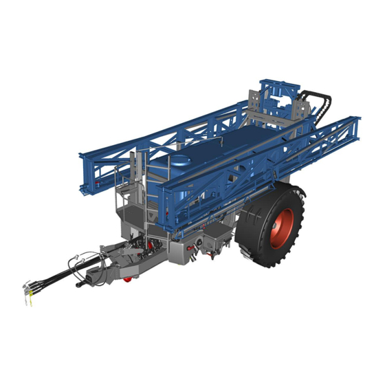
Layout and description LAYOUT AND DESCRIPTION Overview 1 Chassis with drawbar 6 Pumps 2 Drawbar end piece with draw- 7 Control and connection centre bar eye 3 Axle 8 Chemical inductor 4 Wheels 9 Lift mast with pendulum system 5 Main tank with integrated clean 10 Boom water tank... -
Page 41: Chassis, General
Layout and description Chassis, general The chassis forms the base for the attachment of other modules. The chassis consists of: Drawbar Drawbar extension End section Drawbar eye 5.2.1 Drawbar with end section and drawbar eye The drawbar is the connection between the chassis and the drawbar eye. The implement has a rigid or steerable drawbar. -
Page 42: Drawbar - Manual Steerable
Layout and description 5.2.3 Drawbar - manual steerable In the case of manual drawbar steering, the drawbar can be adjusted using two hy- draulic cylinders (1). 5.2.4 Drawbar - automatic steerability (TRAIL-Control) The automatic drawbar steering with the control "TRAIL-Control" is a drawbar steer- ing system based on track-true following. -
Page 43: Axles
The axle of the implement is implemented as a running axle or a braked axle. The permissible axle load is indicated on the Lemken axle type plate (1). The implement may only be used with a running axle if the empty weight of the tractor is at least double the permissible total weight of the filled implement. -
Page 44: Compressed Air Brake With Brake Force Regulator
Layout and description Safety chain According to national regulations, a safety chain (1) may be required for implements without a brake system. The safety chain is only intended as a safety component. The safety chain must not be used for any other purpose. 5.4.2 Compressed air brake with brake force regulator The compressed air brake has the follow- ing brake functions:... - Page 45 Layout and description Brake force regulator (4) Double release valve with manoeuvring valve (5) and park valve (6) Brake valve (7) Compressed air tank (8) with drain valve Combination brake cylinder (10) with: Guiding screw (11) ...
- Page 46 Layout and description Service brake For proper function, the tractor must supply compressed air to the service brake. If the brake lines of the implement are connected to the tractor, the compressed air brake of the implement is supplied with compressed air through the red brake cou- pling.
- Page 47 Layout and description The brake force regulator (4) allows the user to adjust the braking force to the filling of the implement. Select the appropriate position of the brake force regulator. Rstat* Implement [mm] 783 – 830 Empty Half full Full Albatros 4000 Empty...
-
Page 48: Compressed Air Brake With Alb Regulator
Layout and description Parking brake Only when the guiding screw (1) has been removed and placed and secured in the holder (2), is the parking brake ready for operation. The parking brake is operated via the park valve (3). Activate parking brake: Pull the park valve (3). - Page 49 Layout and description Overview The compressed air brake comprises the following components: Brake coupling (1) yellow (control line) Brake coupling (2) red (supply line) Air filter (3) Double release valve with manoeuvring valve (4) and park valve (5) ...
- Page 50 Layout and description Level control (7) Compressed air tank of the braking sys- tem (8) with drain valve Overflow valve (9) Second compressed air tank (10) with drain valve Combination brake cylinder (11) with: Guiding screw (12) ...
- Page 51 Layout and description Service brake For proper function, the tractor must supply compressed air to the service brake. If the brake lines of the implement are connected to the tractor, the compressed air brake of the implement is supplied with compressed air through the red brake cou- pling.
- Page 52 Layout and description The brake pressure is adjusted automati- cally as follows: The compressed air tank of the braking system (3) supplies the air suspension (6) via the overflow valve (4) and another compressed air tank (5). Depending on the weight of the implement, there is control pressure in the spring bel- lows of the air suspension (6).
- Page 53 Layout and description The height is detected by the boom (9) and adjusted with the valve (10). Without a supply of compressed air, the implement is braked and cannot be ma- noeuvred. If the user wants to manoeuvre the imple- ment in an uncoupled state, the user can release the service brake via the manoeu- vring valve (11).
-
Page 54: Hydraulic Braking System
Layout and description The parking brake is operated via the park valve (3). Activate parking brake: Pull the park valve (3). Release the parking brake: Push the park valve (3). Rapid emergency brake If the brake lines are interrupted when the implement is disconnected from the tractor, emergency braking is automatically en- gaged, using the operating pressure of the... - Page 55 Layout and description When the tractor brake pedal is actuated, the hydraulic ram (2) extends. The hydrau- lic ram (2) pushes the brake lever (1) into the brake position. Service brake diagram, braked After braking, the tension spring (3) re- tracts the brake lever (1).
- Page 56 Layout and description By opening the brake valve (5), the preten- sioned compression spring (4) actuates the braking system via the hydraulic ram (2) and the brake lever (1). Parking brake, braked Activate parking brake: Pull the break away cable (6) manually. ...
-
Page 57: Liquid Flow
Layout and description Liquid flow 5.5.1 Overview 14 13 Clean water tank Canister rinsing nozzle Control valve Connection for cleaning gun Self-cleaning pressure filter Pressure control valve Flowmeter External cleaning Agitator Nozzle line Internal cleaning of main tank Part-width section valves Main tank Central bypass valve Drain valve... -
Page 58: Description Of The Spraying Process
Layout and description 5.5.2 Description of the spraying process During the spraying process, the spray pump (H) draws the spraying fluid from the main tank via the selection valve (A) and the suction filter (9). The spraying fluid is then pumped to the nozzles via the diverting valve (D) and the pressure filter (3). The control valve (2) can be used to control the metering of the distribution rate. -
Page 59: Liquid Flow To Nozzles
Layout and description The pressure sensor (23) records the spray pressure for the control. The flush valve (F) on the pressure filter (3) allows you to adjust the flushing intensity of the pressure filter. The pressure control valve (17) directs the spraying fluid to the agitator (5) when the system pressure is exceeded. -
Page 60: Main Tank
Layout and description terminal precisely, it is then necessary to reprogram the part-width sections at the operation terminal. So the main switch of the operation terminal must always be used to switch off the entire sprayer boom. Exception: System cleaning with partially filled main container The pressure sensor for pressure indication is positioned in front of the part-width section valve on the operation terminal. - Page 61 Layout and description Internal cleaning nozzles (4) are provided to clean the interior of the main tank with clean water. The device is equipped with a hydraulic agitator (5). The agitator is used to mix the carrier liquid (water or fertiliser) with the spraying agent, use it in an even concentration and hold it.
-
Page 62: Clean Water Tank
Layout and description Clean water tank The clean water tank is designed for re- ceiving clean water. The clean water can be used for: Internal cleaning Thinning technical remaining quantity System cleaning with empty and par- tially filled main tank ... -
Page 63: Filter
Layout and description Filter Functional and clean filters are a prerequi- site for trouble-free operation. The device comes complete with the fol- lowing filters: Two suction filters (1) which filter the suction-side volumetric flow to the pump. One pressure filter (2) which filters the pressure-side volumetric flow to the noz- zles. -
Page 64: Cardan Shaft
Layout and description 3 Drive 4 Intake connections 5 Pressure connections 6 Oil filling opening 7 Oil level indicator 8 Drain screw (not shown) 5.10.1 Cardan shaft The implement is equipped as standard with a cardan shaft. 5.10.2 Hydraulic drive With a hydraulically-driven pump, the pump (1) is driven by a hydraulic motor (2). -
Page 65: Control And Connection Centre
Layout and description 5.11 Control and connection centre The following positional designa- tions correspond to the position markings of the fluid lines, see "Liquid flow, page 55". Selection valve spray pump Selection valve agitator pump Distributing valve Agitator control Flush valve Suction valve Pressure filter Suction filter... -
Page 66: Distributing Valve
Layout and description Selection valve agitator pump Pictogram Switch position Description Selector valve (B) is opened to the external connection. The spraying fluid in the main tank is not stirred. Selector valve (B) is switched to the main tank. ... -
Page 67: Flush Valve
Layout and description 5.11.4 Flush valve The flush valve (1) is used to seamlessly adjust the pressure filter (2) purging. When the flush valve is open, dirt particles are collected by the pressure filter and re- turned to the main tank. 5.11.5 Chemical inductor Spraying agents can be poured into the main tank via the induction gate. - Page 68 Layout and description Canister flushing nozzle (7) Empty spray agent canisters can be rinsed out with the canister flushing noz- zle. The cleaning intensity can be varied using the valve canister flushing nozzle (3). Agitator nozzle (8) The agitator nozzle allows the spray agent to be dissolved and pre-mixed.
-
Page 69: Connections
Layout and description 5.11.6 Connections The following connections are available: Filling opening (1) of the water canister for hand washing Filling connection (2) of the clean water tank Intake connection (3) External cleaning/pumping (4) Filling port (not shown) 5.11.7 Pressure limit valves The maximum system pressure of the im- plement is set via the pressure limiting... -
Page 70: Fill Level Indicator And Tank-Control
Layout and description 5.11.8 Fill level indicator and TANK-Control The fill level indicator (1) is visible on the main tank. As an option, the contents of the main tank can also be viewed in the control and at the control centre via a separate display unit. -
Page 71: Distance Detection
Layout and description 5.14 Distance detection The distance pulses for automatic operation of the implement are detected from the wheel. In the case of braked axles, the speed is detected by means of a pole wheel which is integrated into the brake drum (1). In the case of running axles (2), the speed is detected by means of an external sensor (3). -
Page 72: Flowmeter
Layout and description 5.15 Flowmeter The flowmeter (1) measures the quantity of spraying fluid flowing to the nozzles. In the operation terminal, the sprayed litres per minute (l/min) are displayed. 5.16 Pressure measuring device The pressure measuring device is provided for monitoring the spray pressure (Auto- matic mode) and for the indirect indication of filter contamination. -
Page 73: Operation Terminal
Layout and description 5.18 Operation terminal The LEMKEN CCI-50 operation terminal is used to operate the electronic control of the device For general operation of the CCI operation terminal, see separate operating instructions Competence Center ISOBUS e.V. 5.19 Height adjustment The height of the sprayer boom is adjusted via a hydraulic cylinder (1) on the lift mast. -
Page 74: Stabiliser
Layout and description 5.21 Stabiliser The stabiliser (1) damps the swing sus- pension and therefore provides a better position of the boom on slopes. 5.22 Boom 1 Boom 2 Height adjustment 3 Centre piece 4 Arm 1 5 Arm 2 6 Arm 3 7 Guard plate 8 Nozzle holders... -
Page 75: Part-Width Section Valves
Layout and description 5.22.1 Part-width section valves The nozzles of an arm are combined in sections. Using the part-width section valves on the boom, the user can switch all the nozzles or individual sections on or off. 5.22.2 Single nozzle valves The nozzles on the outer arms on the left and right are controlled by single nozzle valves. -
Page 76: Nozzles
Layout and description 5.22.4 Nozzles The user can attach different nozzles to the nozzle holders. Each nozzle type has different volumetric flows, spray patterns, drop sizes and nozzle characteristics. The following aspects must be observed when selecting nozzles: Spraying agent used ... -
Page 77: Drag Hose
Layout and description 5.23 Drag hose The drag hoses (1) are intended for the application of liquid fertilizer. Burning of foliage is hardly possible, due to the direct application onto the ground. -
Page 78: Preparations
Preparations PREPARATIONS Preparations on tractor 6.1.1 Checking the suitability of the tractor for the implement Check the following before attaching the implement to the tractor: Check the required voltage sources Check the voltage sources of the tractor. A voltage source is available on the tractor for each device drawing power. - Page 79 Preparations If several devices drawing power are con- nected to a single socket: Please note that according to DIN 9680, the fuse protection must be at least 25 A per socket. Where applicable, use multiple sockets with separate fuses. ...
-
Page 80: Check Tractor Tire Pressure
Preparations Devices drawing power EW DW DR Boom flaps Green P2/T2 Height adjustment of the Blue boom up to B30 Height adjustment of the Blue boom starting at B33 TRAIL-Control without Yellow/ P11/T11 electro-hydraulics white Load-sensing for TRAIL- Load- Control without electro- sensing hydraulics Yellow/... -
Page 81: Installation Of The Operation Terminal
Preparations 6.1.3 Installation of the operation terminal Mount the holder for the operation termi- nal in the visible area and the user's grip area. Ensure that no electrical or fluid-carrying cables are damaged during drilling. WARNING: Damaged lines can lead to accidents. -
Page 82: Preparations On The Implement
Preparations Preparations on the implement 6.2.1 Standard procedure To set up the implement in general: Attach implement. Check whether the implement is horizon- tal in the direction of travel. If the implement is NOT horizontal in the direction travel: Have the drawbar adjustment adapted by service personnel. -
Page 83: Implement With Compressed Air Brake
Preparations 6.2.2 Implement with compressed air brake Risk of accident due to deactivated brakes In order to enable unloading and manoeuvring without a com- DANGER pressed air supply, the brake cylinders and thus the entire com- pressed air brake were disabled at the factory by means of guid- ing screws. -
Page 84: Attaching The Implement
Preparations Insert the guiding screw (1) into the holder (5) on the brake cylinder (3). Secure the guiding screw (1) using a peg and nut. Attaching the implement Target: Device is fully available for distri- bution. Application: Before using ATTENTION: To protect the tractor and the implement, the latter is suspended in a horizontal position at a max. - Page 85 Preparations If the trailer coupling on the tractor can- not be adjusted to allow horizontal sus- pension of the device, the device can be converted. See "Conversion of device, page 84". Slowly and carefully, pull the tractor's trailer coupling up to the towing eye of the implement.
-
Page 86: Conversion Of Device
Here, the following options apply: Allow the height of the towing eye im- plement to be adjusted by re-screwing. Have other traction loops approved by LEMKEN installed, see "Traction loops, page 195". Allow other drawbar end piece to be mounted. -
Page 87: Implement With Hydraulic Braking System
Preparations Connect the brake couplings (1) of the device to the tractor. With a manual brake force regulator: Set manual control (2) to the required position. Press the red button (3) to release the parking brake of the device. 6.3.3 Implement with hydraulic braking system Release the parking brake: ... - Page 88 Preparations Largest possible profile coverage (PuLb) of the cardan shaft Where applicable, use a longer cardan shaft Add the cardan shaft operating instruc- tions to the operating manual of the de- vice. Mount one of the following PTO shaft ends to the tractor: ...
- Page 89 Preparations Hold the cut-off piece of the outer pro- tective tube (2) over the outer profile tube (8) and cut the outer profile tube (8) at a right angle. Hold the cut-off piece of the inner protec- tion tube (2) over the inner profile tube (9) and cut off the inner profile tube (9) at a right angle.
-
Page 90: Determining The Filling Capacity Of The Implement
Preparations Determining the filling capacity of the implement To determine the permissible filling capacity of the implement [l/kg] the following data and procedures must be taken into account: Implement table Recording of data from Determination of the Determination of the da- the implement type plate data by weighing ta by calculation... - Page 91 Preparations With the implement empty, drive onto a weighbridge, so that only the axle is standing on the scale. Determine the axle load of the implement (example 3000 kg). Calculate the permissible axle load [kg] by subtracting the actual axle load of the empty implement from the permissible axle load of the implement (e.g.: 6000 kg –...
-
Page 92: Installation Of The Correct Nozzles
Preparations Installation of the correct nozzles The mesh size of the pressure filter and the nozzle filter must al- ways be the same as or smaller than the flow cross-section of the nozzles which are used. The details by the agricultural chemical manufacturer with regard to suitable mesh sizes must be observed. - Page 93 Preparations Place the three-nozzle holder or the four-nozzle holder in the correct nozzles. If not all nozzles of a segment are required: in case of single nozzle holders, close the individual nozzles with caps (1). in case of multiple nozzle holders, place these in the closed position between the individual nozzles.
-
Page 94: Volumetric Metering Of The Nozzles And Calibrating The Flowmeter
Preparations A = Nozzle spacing 0.5 m H = Spraying height 1.0 m Volumetric metering of the nozzles and calibrating the flowmeter Automatic control of the distribution rate [l/ha] is achieved via the travel speed and the flow of the spraying fluid through the nozzles. -
Page 95: Volumetrically Meter The Nozzles
Preparations Applications: Before commissioning for the first time At the start of each season If the distribution rate displayed differs from the actual distribution rate sprayed When the flowmeter has been replaced or repaired Preconditions: The general approach taken to working with the control system is well known. - Page 96 Preparations Secure the tractor-device combination to prevent it from rolling away. Completely extend sprayer boom. Switch on the PTO shaft. Run the PTO shaft at the specified speed. Adjusting the control Select the manual mode to control the distribution rate in the control system.
-
Page 97: Calibrate The Flowmeter
Preparations Compare the amount of water applied by the individual nozzles. If the output quantities of the measured nozzles are equal and the l/min value cor- responds to the value of the nozzle table: Calibrate the flowmeter. If the output quantities of the measured nozzles are the same and the l/min value deviates from the value in the nozzle table: ... -
Page 98: Calibration Of The Speed Sensor
Preparations The way the pulse values are made avail- able to the control is described in the oper- ating instructions manual "SPRAYER controller MIDI" in the chapter "7.5 Calibrating the flowmeter". Calibration of the speed sensor 6.7.1 Check speed sensor For automatic metering with the operation terminal, the distance impulses have to be taken from the device and calibrated to... -
Page 99: Check Compatibility Of Pesticides With Equipment
Preparations The operating instructions in the "SPRAY- ER controller MIDI" manual describe how to calibrate the speed sensor in chapter "7.6 Selecting and configuring the speed sensor". Check compatibility of pesticides with equipment Specially approved pesticides and mixed - compounds may have an adverse effect on the device materials. - Page 100 Preparations If the following indications are apparent, do not use the pesticide: Pesticide tends to solidify or clump. Hoses become particularly soft. Seals or membrane sources.
-
Page 101: Operation
Operation OPERATION Prepare device for use 7.1.1 Adapt device for use Target: The external conditions and equipment of the device are appropriate for the intended use. Check the following before distribution and adjust if necessary: Check whether the unit contains anti- freeze. -
Page 102: Prepare The Device For Operation In Frosty Conditions
Operation 7.1.2 Prepare the device for operation in frosty conditions Risk of accident due to frozen braking system of the device WARNING If the braking system of the device is frozen, it is no longer possi- ble to brake the device. This may even be fatal or result in serious injuries. -
Page 103: Fill Device With Liquids
Operation 7.1.3 Fill device with liquids Target: All the necessary liquids are avail- able for use. Fill the following containers with liquids: Fill the handwash container with water, see "Filling water canister for hand washing, page 102". For cleaning purposes on the fieldFill the clean water tank with water, see "Filling the clean water tank, page 103". -
Page 104: Filling And Emptying The Water Canister For Hand Washing
Operation Filling and emptying the water canister for hand washing The water canister for hand washing is in- tended exclusively for cleaning purposes and is not suitable for housing cleaning agents and sprays. CAUTION: Germs or traces of cleaning agents and sprays may contaminate the water canister for hand washing. -
Page 105: Filling And Emptying The Clean Water Tank
Operation Filling and emptying the clean water tank The clean water tank of the implement is integrated in the main tank. The clean water tank is intended for clean- ing purposes. The entire piping system and the implement functions are designed to fill the clean water tanks exclusively with clean water. -
Page 106: Emptying The Clean Water Tank
Operation Unscrew the blind cap (4) and remove it. Mount the hose at the filling connection. Fill the clear water tank. Monitor filling of the clean water tank via the level indicator (1). To ensure the clean water tank does not overflow: Stop filling the clean water tank in good time. -
Page 107: Filling Main Container
Operation Filling main container The main tank can be filled with water and spraying agent. Depending on the filling agent, the following feed options are provided: Feed Filling agent External filling connection Water and ready-mixed spraying fluid Intake connection Water and ready-mixed spraying fluid Chemical inductor Unmixed or ready-mixed spraying fluid 7.4.1 Standard procedure... -
Page 108: External Filling Connection
Operation Depending on the spray agent, first fill the main tank with approx. 100 l water. Add undiluted spraying agent or mixed spraying liquid. Fill the main tank up to the desired spray agent quantity with water, not exceeding the nominal volume. - Page 109 Operation Monitor the filling of the main tank with the following aids: Fill level indicator (4) Display unit at the operating and ad- justment centre Operation terminal To ensure the main container does not overflow: Stop filling the main tank in time.
-
Page 110: Intake Connection
Operation 7.4.3 Intake connection Application: Pump water or ready-mixed spraying fluid with the intake connection into the main tank. The maximum suction depth with a filling hose is 2.5 m. *Position designations correspond to the position des- ignations of the fluid lines, see "Liquid flow, page 55". Approach* ... - Page 111 Operation Set agitator regulation (E) to maximum. Switch diverting valve to spraying mode. Monitor the filling of the main tank with the following aids: Fill level indicator (4) Display unit at the operating and ad- justment centre ...
-
Page 112: Chemical Inductor
Operation 7.4.4 Chemical inductor Application: Rinse unmixed or ready- mixed spraying fluid into the main tank. Prerequisite: The main tank is filled with water or fertilizer solution according to the instructions of the respective spray agent manufacturer. Fold the lever (1) on the induction lock upwards. - Page 113 Operation For the storage of small spray agent con- tainers or a measuring cup, the tray can be folded upwards. For storing small spray agent containers or a measuring cup: Swivel the shelf (2) upwards. Swivel the holder (3) underneath the shelf (2).
- Page 114 Operation Switch on pump via PTO shaft. Operate the pump at the rated speed. Switch the diverting valve to the induc- tion lock. If necessary, regulate the performance of the agitator regulation. Open the valve for edge moistening and fill approx.
- Page 115 Operation After rinsing the spray agent: Clean the empty spray agent canister. See "Cleaning empty canisters, page 115". Rinse the chemical inductor with clean water. See "Flushing the induction sys- tem, page 120". If canisters are not cleaned or the pipe sys- tem is flushed: ...
-
Page 116: Adjust Flush Valve
Operation Adjust flush valve Targets: Pressure filter does not clog. Flushing valve adjustment (1) matches distribution rate[l/ha]. Application: Configure automatic distribu- tion. Additional information: Dirt particles col- lected by the pressure filter are returned to the main tank via the rinsing valve and the agitator. -
Page 117: Cleaning Empty Canisters
Operation In the control: Manual mode for control- ling the distribution rate. The work mask view changes. To close the control valve: Press and hold softkey for 10 seconds. To open the control valve slightly: Press and hold softkey for 3 seconds. ... - Page 118 Operation Open the cover Fold the cleaning nozzle (1) upwards. Push an empty canister onto the clean- ing nozzle (1). Switch the selector switch to the fresh water tank. Switch the distributor valve to induction. ...
- Page 119 Operation Suck the induction hopper empty. Close the suction valve. Fold the cleaning nozzle (1) downwards. Close the cover Switch the selector switch to the main tank. Switch the distributor valve to spraying. In order to use the water in the fresh water tank as effectively as possible, we recommend that water is sucked in with a filler hose via the filler connection of the selector valve for canister cleaning and cleaning of the induction system.
-
Page 120: Cleaning Gun On The Induction Hopper
Operation Cleaning gun on the induction hopper Observe the relevant standards and regulations for cleaning the implement. The cleaning gun must only be operated with fresh water. Switch the selector switch to the fresh water tank. Switch on the pump. ... - Page 121 Operation Remove the cleaning gun (1) from the holder (2). Switch the distributor valve to the induc- tion hopper. Switch the cleaning gun lever up to ON. The effect of the cleaning gun can be con- tinuously regulated with the lever (1). ...
-
Page 122: Flushing The Induction System
Operation Clean empty canisters or the induction hopper container. After cleaning: Close the cleaning gun lever by switch- ing it down to OFF. Place the cleaning gun in the holder (2). Because of the limited content of the fresh water tank we recom- mend that ... - Page 123 Operation Close the cover (1) of the induction con- tainer. To flush the induction system, switch the following levers up into the ON position: Canister flushing nozzle Edge wetting Agitator nozzle Open the suction valve so far that no liq- uid can escape from the induction con- tainer.
-
Page 124: Folding Out Sprayer Boom
Operation Edge wetting Agitator nozzle Close the suction valve. Switch the selector switch to the main tank. Switch the distributor valve to spraying. Because of the limited content of the fresh water tank we recom- mend that for ... -
Page 125: Standard Procedure
Operation Potentially fatal electric shock due to overhead lines DANGER The unit can reach the height of overhead lines when folded out. This could cause an electrical accident that leads to a potentially fatal electric shock or fire. Never fold the device in and out near overhead lines. 7.9.1 Standard procedure ... -
Page 126: Adjusting The Spring Stabiliser
Operation the working position. For how to fold in the sprayer boom, see "Fold in sprayer boom, page 132". 7.10 Adjusting the spring stabiliser The spring stabiliser can be adjusted to suit the terrain. In the basic setting of the spring stabiliser, 15 chain links (1) are attached. -
Page 127: Trial Operation Of Device
Operation 7.11 Trial operation of device Applications: Initial start-up Getting to know the individual control functions Before initial use with spraying agents After maintenance operations After repairs Put the ladder in the transport position: ... -
Page 128: Working With The Device
Operation Perform trial spraying operation: Switch on the nozzles. Work with the device, see "Working with the device, page 126". Check all components for function and leak tightness. Check spray result. 7.12 Working with the device Preconditions: ... -
Page 129: Apply Spraying Agent
Operation Set selection valve to main tank. Set diverting valve to spray mode. Adjust the agitator control to the agitator intensity according to the usage instruc- tions of the spraying agent used. Set the control unit according to the in- tended distribution. - Page 130 Operation To avoid the spraying agent drifting: First spray the outer perimeter of the property with drift-free nozzles. Use low drift nozzles or boundary nozzles.or Switch off any outer nozzles. Then spray the inside of the spray lanes with application-specific nozzles.
-
Page 131: Working On Rugged Terrain Or On A Slope
Operation If distribution is interrupted: Rinse the piping system with clean water, see "Stirring spraying fluid be- fore distribution, page 137". Stir the spraying fluid before re- applying, see "Flush the pipe system before interruption, page 135". ... -
Page 132: Switch On The Spraying Cone Lighting
Operation 7.14 Switch on the spraying cone lighting The spraying cone lighting can be switched via the control unit. See operating manual SPRAYER control- ler MIDI, Chapter 6.10 Operating additional functions - activate/deactivate working lights. 7.15 Working with drop hoses 7.15.1 Attaching drop hoses ... -
Page 133: Spraying With Drop Hoses
Operation Install drop hoses (6) with the inserted seals and metering washers (7) on the nozzle holders. Carefully fold in the sprayer boom. The drop hoses may not get caught on any components or stuck in the wheels. -
Page 134: Fold In Sprayer Boom
Operation 7.16 Fold in sprayer boom Applications: Before driving on the road When parking When turning or negotiating headlands Potentially fatal electric shock due to overhead lines DANGER The unit can reach the height of overhead lines when folded out. This could cause an electrical accident that leads to a potentially fatal electric shock or fire. -
Page 135: System Cleaning With Partially Filled Main Container
Operation Raise the sprayer boom to the stops (1). ATTENTION: The sprayer boom swings when the device moves.When the sprayer boom reaches the topmost posi- tion on the lift mast, the sprayer boom is realigned. Fold in the sprayer boom with the tractor control unit. - Page 136 Operation General procedure: Rinse the piping system prior to interrup- tion. Stir spraying fluid before resuming distri- bution. System cleaning conditions for partially filled main tank: The concentration of the spray agent remains unchanged. No clean water flows into the main tank. ...
-
Page 137: Flush The Pipe System Before Interruption
Operation 7.17.1 Flush the pipe system before interruption Description* * Position designations correspond to the position designations of the fluid lines. The spray pump (H) draws the water from the clean water tank via the selection valve (A) and the suction filter (9). The water is then pumped to the nozzles via the divert- ing valve (D) and the pressure filter (3). - Page 138 Operation Switch off pump (H) via PTO shaft. Close flushing valve (F). Remember the number of turns to close the valve. This adjustment is required after the sys- tem has been cleaned. Set the selection valve of the spray pump (A) to clean water tank.
-
Page 139: Stirring Spraying Fluid Before Distribution
Operation Open and close part-width section valves (20) via the control. ATTENTION: Only switch the part-width section valves. If the nozzles are switched off via the control, the central bypass valve (21) opens and the water is pumped into the main tank. ... - Page 140 Operation Application: Distribution continued after an interruption. Prerequisite: To ensure the correct con- centration of the spraying fluid, do not spray while stirring. Description The agitator pump (I) draws the spraying fluid from the main tank via the selection valve (B) and the suction filter (9). The spraying fluid is pumped into the main tank (7) via the agitator regulation (E/105) and the agitator (5).
-
Page 141: After Stirring
Operation Switch on the pump (I) via the PTO shaft. Operate the pump at the maximum per- missible speed (540 rpm). Stir the contents of the main tank until the spray agent has completely mixed again (at least 10 minutes). 7.17.3 After stirring ... -
Page 142: Cleaning
Cleaning CLEANING Standard procedure Remaining quantities of spraying agent must not be drained off at ATTENTION the edges of the road or discharged into the sewer system. Where possible: Reuse collected spraying agent (after consult- ing the respective spraying agent manufacturer). ... -
Page 143: Emptying The Main Tank
Cleaning The following should be noted during the cleaning: Regulations of the spraying agent manu- facturer Regulations of the nozzle manufacturer These operating instructions Other regulations for handling spraying agents Standard procedure: Emptying main container, see "Emptying the main tank, page 141". -
Page 144: Pump The Remaining Quantity From The Main Container
Cleaning To empty the main tank the spraying agent must be pumped into an external tank, the residual content in the main tank must be drained off. Main tank pumping and draining is also required when spraying agent remains in the main tank during spraying intervals, and it is unable to be agitated because of deposits, bonding etc. -
Page 145: Draining Spraying Agent Out Of The Main Tank
Cleaning After pumping out: Switch off pump via PTO shaft. Remove hose. Close pump connection with sealing cap. After the remaining quantity has been pumped out, internal cleaning is neces- sary, see "Internal cleaning, page 144". 8.2.3 Draining spraying agent out of the main tank ... -
Page 146: Internal Cleaning
Cleaning Close the drain valve (2). Replace the screw cap (3). Check that the connector does not leak. Carry out internal cleaning, and external cleaning and filter cleaning if necessary. Internal cleaning ATTENTION Deposits from the spray solution contaminate the main tank, the piping system and the nozzles. -
Page 147: Standard Procedure
Cleaning Additional information: Depending on the pesticide and subsequent intended use, the main container, piping system and nozzles may have to be cleaned with cleaning agents.Please refer in this case to the operating instructions for the pesticide products and cleaning agents used. 8.3.1 Standard procedure Preconditions: ... -
Page 148: Clean Main Container
Cleaning Reduce spray pressure. Move with increased travel speed. Open and close part-width section valves (20) with the switchbox. Spray out the contents of the main tank: Until air comes out of the nozzles. Until a pressure drop of 1 bar occurs at the nozzles. - Page 149 Cleaning As soon as spraying fluid is present in the main tank (7), the agitator pump (I) draws the spraying fluid via the selection valve (B) and the suction filter (9) from the main tank. The spraying fluid is then fed into the main tank via the agitator control (E) and the agitator (5).
-
Page 150: External Cleaning
Cleaning When the main tank contains approx. 80 - 90 l: Stop internal cleaning: Set distributor valve (D) to spray. At the same time, set the selection valve (A) to the main tank. For more, see "Standard procedure, page 145". -
Page 151: Prepare External Cleaning
Cleaning Preconditions: Distribution was carried out. The main container is cleaned from in- side. See "Internal cleaning, page 144". If necessary, take cleaning agent and equipment with you to apply the cleaning agent, e.g. pump sprayer. If necessary, carry suitable accessories, e.g. -
Page 152: Perform External Cleaning
Cleaning Check whether the drain connection (1) is sealed with a blind cap. ATTENTION: If the drain connection is not closed with a blind cap, liquid may escape from the unit when switching the selector valve to external clean- ing/pumping. -
Page 153: Cleaning The Filter
Cleaning Where applicable, spray device with cleaning agent. Use an external device, e.g. a pump sprayer, to apply the cleaning agent. Rinse device with water. After the external cleaning: Pull and release the hose in a jerk. The hose is automatically wound onto the hose reel. -
Page 154: Suction Filter
Cleaning 8.5.2 Suction filter Prerequisite: The filling connection is closed with a sealing cap. Remove the seal (1). Loosen (3) union nut. Remove the suction filter (2). Clean the individual components of the suction filter with water and a soft brush. ... - Page 155 Cleaning Remaining spray agent is drained from the pressure filter (3) and system through the rinsing valve. Flushing valve (F) closed to the stop by turning it to the right. Procedure Loosen the union nut (2) of the pressure filter.
-
Page 156: Uncoupling The Implement
Uncoupling the implement UNCOUPLING THE IMPLEMENT Preparations Aim: The implement is safely stored un- derneath until the next use. Applications: For wintering After one use Preconditions: All tanks are empty. Implement is cleaned, see «Cleaning, page 140». ... -
Page 157: After One Use
Uncoupling the implement If there is no freeze-free storage space available: Provide biodegradable antifreeze. ATTENTION: Do not use liquid fertiliser. Liquid fertiliser will damage the rubber components. Observe the operating instructions and the safety data sheet of the antifreeze agent. -
Page 158: Put Implement Into Park Mode
Uncoupling the implement Put implement into park mode Engage brakes: Implement with compressed air brake: Pull the park valve (1) of the parking brake. Implement with hydraulic braking sys- tem: Pull the break away cable (2) man- ually. - Page 159 Uncoupling the implement For implement without braking system: Release the safety chain from the trac- tor. Push pin (4) of the safety chain in- wards. Unlock the locking device (5): Press the locking device against the hook (6).
-
Page 160: Detaching The Implement
Uncoupling the implement Detaching the implement Uncouple the brake lines from the trac- tor. For hydraulic braking system: Attach the brake lines to the holders on the implement side. Uncouple the cardan shaft from the trac- tor. ... -
Page 161: Maintenance And Servicing
Maintenance and servicing MAINTENANCE AND SERVICING 10.1 Safely maintain the device Personnel For certain activities, e.g. braking system work, service personnel (e.g. in agricultural machinery workshops) are required. These activities are marked in the maintenance schedule. Preparations Switch off the device. ... -
Page 162: Environmental Protection
Maintenance and servicing During the maintenance and repair To prevent accidents and injuries: Wear protective equipment. Use the following instruments: Suitable tools Climbing aids Supporting elements For dismantling and mounting heavy components:Use hoisting gear. ... -
Page 163: Maintenance Intervals
Maintenance and servicing 10.2 Maintenance intervals Interval Activity Hose connections Pins, bolts etc. Piston rods hydraulic ram Slide pipes Cardan shaft Joints Traction loop Traction loop/Traction loop cou- pling Parking support Storage of the drawbar Steering cylinder Ropes Axle slack adjuster Axle camshafts Gearbox Connecting sleeve, gearbox... -
Page 164: Oils And Lubricants
Maintenance and servicing Interval Activity Bolted connections Hydraulic hoses Air filter, compressed air brake Chemical inductor Pump Pressure accumulator, pump Axle Braking system 10.3 Oils and lubricants Amount mainte- Assembly group Oil / lubricant nance interval Grease nipple and open lu- Multi-purpose grease Depending on the lubrica- brication points... -
Page 165: Lubricating
Maintenance and servicing 10.4 Lubricating Eye injuries due to grease WARNING When lubricating the lubrication points, grease can escape be- tween components at high pressure and cause injury to the eyes. When lubricating components, wear protective clothing, espe- cially safety glasses. ... -
Page 166: Stand
Maintenance and servicing Lubricate contact surface of the traction loop (1). Lubricate grease nipple (2). 10.4.3 Stand Lubrication interval: Every 8 operating hours Lubricate grease nipple (1). -
Page 167: Storage Of The Drawbar
Maintenance and servicing 10.4.4 Storage of the drawbar Lubrication interval: Every 8 operating hours Lubricate grease nipple (1). 10.4.5 Steering cylinder Lubrication interval: Every 8 operating hours Lubricate grease nipple (1). 10.4.6 Slack adjuster Lubrication interval: ... -
Page 168: Camshaft
Maintenance and servicing Lubricate grease nipple (1). 10.4.7 Camshaft Lubrication interval: Every 8 operating hours Lubricate grease nipple (1). 10.4.8 Connecting sleeves of the pump Lubrication interval: Every 50 operating hours... - Page 169 Maintenance and servicing Manually rotate the cardan shaft (1) un- coupled from the tractor to be able to lu- bricate the grease nipples through the guard (2). Lubricate grease nipple (3). Lubricate grease nipple (4).
-
Page 170: Lift Mast And Self-Aligning Bearings
Maintenance and servicing Lubricate contact surface of the traction loop (1). Lubricate grease nipple (2). 10.4.9 Lift mast and self-aligning bearings Lubrication interval: Every 8 operating hours Lubricate both sliding surfaces on the lift mast (1) using a brush. -
Page 171: Skids And Pivoted Guide
Maintenance and servicing Lubricate the four sliding surfaces on the lift mast (2) using a paintbrush. To lubricate these sliding surfaces, use chain and adhesive lubricant OKS Mox-Active 451. 10.4.10 Skids and pivoted guide Lubrication interval: Every 8 operating hours ... -
Page 172: Cable Pulley
Maintenance and servicing 10.4.11 Cable pulley Lubrication interval: Every 8 operating hours Lubricate the grease nipple on the pulley (1). 10.4.12 Cable Lubrication interval: Every 50 operating hours After cleaning, lubricate the ropes with lubricant for wire ropes. 10.4.13 Sprayer boom Lubrication interval:... - Page 173 Maintenance and servicing The following lubrication points are located on the right and left side of the boom. Im- ages with the lubrication points are only shown from one side of the boom. The number of lubrication points shown refers to the total number of points on both the right and left side of the boom.
- Page 174 Maintenance and servicing Pivot joint 2 Lubricate 4 grease nipples on pivot joint 2 (1). Lubricate 2 grease nipples on strut (2). Lubricate 4 grease nipples on the folding lever (3). Folding cylinder Boom with 2 folding cylinders: ...
- Page 175 Maintenance and servicing Deflection joint Lubricate the 4 grease nipples on the deflection joint (1). Pivot joint 3 Lubricate 4 grease nipples on folding lever 3 (1).
-
Page 176: Chemical Inductor
Maintenance and servicing Lubricate 4 grease nipples on the folding lever 2 (2). 10.4.14 Chemical inductor Lubrication interval: Every 8 operating hours Lubricate the 4 grease nipples on the holder (1). 10.5 Drive shaft Use lithium-lubricated grease, consistency class NL-G12. -
Page 177: Protective Tube
Maintenance and servicing The drive shaft must be serviced on the tractor side and the implement side. Protective tube Safety chain Sliding tube not illustrated (inside the protective tube) Joints 10.5.1 Protective tube The protective tubes of the drive shaft must be checked for damage and wear. ... -
Page 178: Hydraulic Hoses
Check the manufacturing date of the hy- draulic hoses. Replace after 6 years at the latest. Only use hydraulic hoses approved by LEMKEN. 10.7 Oil filter in electro-hydraulic operation Dirty oil results in increased wear and damage to the implement’s hydraulic system. -
Page 179: Check Oil Filter
Maintenance and servicing 10.7.1 Check oil filter Check interval: Every 8 operating hours The oil filter is equipped with a visual con- tamination display with memory function. Contaminants slowly clog up the filter. This leads to a differential pressure between the filter intake and the filter drain. -
Page 180: Air Brake
Maintenance and servicing Switch on the tractor engine. Keep operation terminal off. In order to deaerate the oil filter. Activate the control unit for the electro- hydraulic function for two minutes. Skipping the deaeration step can impair the hydraulic functions on the implement. -
Page 181: Cleaning
Maintenance and servicing Pull the pin of the drain valve (1) to one side until no more air flows out our the compressed air tank. The air brake system is now without pres- sure. 10.8.3 Cleaning DANGER Persons can be injured by the spring pressure of the air filter. ... -
Page 182: Tightening Torques
Maintenance and servicing Fit the air filter (3). Secure the air filter (3) with the sheet metal panel (1). Clean the second air filter. Couple the brake hoses to the tractor. Switch on the tractor engine. When the tractor engine is running, the brake system will automatically be filled with air. -
Page 183: Bolts And Nuts Made Of Steel
Maintenance and servicing The tightening torques set out below refer to screw connections that are not specifically mentioned in these operating instructions. Specific tightening torques to be applied are mentioned in the text. Identify the relevant screw connection by means of the spare- parts list or the markings on the screw head. -
Page 184: Wheel Nuts
Maintenance and servicing Diameter [Nm] M 12 M 14 M 16 M 18 M 20 M 22 M 24 M 27 10.9.4 Wheel nuts The tightening torque for the wheel nuts (1) with centring spring ring (2) is 550 Nm. ... -
Page 185: Check The Connections To The Tractor
Maintenance and servicing 10.10 Check the connections to the tractor 10.10.1 Hydraulic connections Risk of accidents due to escaping hydraulic fluid Hydraulic fluid which is ejected under high pressure (hydraulic oil) WARNING can penetrate the skin and cause serious injuries. In the event of injuries, consult a doctor immediately. -
Page 186: Changing Gear Oil
Maintenance and servicing 10.11 Changing gear oil Interval: After the season Place suitable drip pan under the screw (1). Remove the screw (1). Remove the screw (2). Once oil has been fully drained: Fit the screw (2). ... -
Page 187: Check Oil Level
Maintenance and servicing Annual maintenance performed by a quali- fied and well-trained person: Check pump. Change membrane. Change oil. 10.12.2 Check oil level Inspection interval: Daily After 8 operating hours at the latest If the oil level in the sight glasses (1) is be- tween the minimum mark and the maxi- mum mark, there is sufficient oil in the pump. -
Page 188: Have Membranes Replaced
Maintenance and servicing 10.12.3 Have membranes replaced If the oil in the sight glasses is discoloured white, this indicates damage to the pump membranes. In the event of white discoloration of the oil, stop spraying immediately. CAUTION: Continuing to operate the pump will lead to it being damaged. -
Page 189: Work For A Qualified, Authorised Person
Maintenance and servicing 10.15 Work for a qualified, authorised person ATTENTION: Have the following work car- ried out by a specialist workshop or by trained and instructed members of staff. 10.15.1 Axle Have the following work carried out be- fore the start of the season: ... -
Page 190: Checking The Implement
Maintenance and servicing 10.15.4 Checking the implement Have the following work carried out eve- ry 3 years: Read the pump performance Read and calibrate the flowmeter Read the pressure sensor 10.16 Control connections To check the implement as part of an offi- cial inspection, the implement is equipped with connections for test equipment. -
Page 191: Pressure Gauge
Maintenance and servicing 10.16.2 Pressure gauge Connection (1) for reading the pressure gauge. 10.16.3 Flowmeter Connection (1) for reading the flowmeter. 10.17 Information in case of faults and malfunctions Fault Reason Remedy Slow, continuous pressure Dirty pressure filter Clean the pressure increase with constant appli- filter cation quantity (l/ha) -
Page 192: Technical Data
Technical data TECHNICAL DATA 11.1 Dimensions... - Page 193 Technical data Length (L) Width (W) Height (H) [mm] [mm] [mm] Designation base Minimum Maximum Minimum Maximum Minimum Maximum B 21 5700 6000 2600 2960 3300 3800 B 27 5700 6000 2600 2960 3300 3800 4000 B 30 6000 6300 2600 2960 3300...
-
Page 194: Weight
Technical data 11.2 Weight 11.2.1 Tare weight Tare weight Designation Axle load [kg] Drawbar load [kg] Gross weight [kg] 4000 4375 4960 5000 4973 5680 6000 5047 5860 Depending on the implement design, the actual weights differ from the values shown in the table. -
Page 195: Load Data Of The Implement Depending On The Permissible Wheels
Technical data 11.2.3 Load data of the implement depending on the permissible wheels The load capacity of the tyres is greater than or equal to the axle A: …. /G: …. White background: load The load capacity of the tyres is less A: …./G: …. -
Page 196: Drawbar
Technical data G: 11160 G: 12000 A: 9330 A: 10000 520/85 R 46 173 A8 G: 11160 G: 12000 A: 7800 A: 9330 A: 10000 580/70 R 38 170 A8 G:8990 G: 11160 G: 12000 A: 7800 A: 9330 A: 10000 A: 9720 600/65 R 38 162 A8 G:8990... -
Page 197: Traction Loops
11.5 Traction loops Only use the traction loops specified by LEMKEN. The traction loops must comply with the following minimum technical require- ments: Drawbar load [kg]: 2000 ... -
Page 198: Automatic Drawbar Steering With Trail-Control
Voltage 12 V DC Power supply Connection 3-pole DIN 9680 Fuse 25 A Albatros 10 and 12/4000 1700 mm Minimum track width Albatros 10 and 12/5000 1800 mm Albatros 10 and 12/6000 1900 mm Required limitation of the oil quantity at the tractor control unit: ... -
Page 199: Tyres
Technical data 11.7 Tyres Designation Width [mm] [mm] [mm] [kg] [bar] 270/95 R54 5828 4380 6.00 300/95 R46 5318 3150 4.00 300/95 R52 5818 4380 4.80 340/85 R46 5238 3350 3.60 340/85 R48 (13.6 R48) 5568 4380 4.80 380/90 R46 5495 6900 5.80... -
Page 200: Use Of Own Wheels Or Wheels Which Are Not Listed In The List Of Wheels
Technical data 11.8 Use of own wheels or wheels which are not listed in the list of wheels The axle and braking system of the implement is only deigned for the wheels which are mounted on the implement or the wheels listed in the original order. ... -
Page 201: Rims
Technical data It must also be taken into account that the maximum permissible load bearing capacities of the wheels and the maximum axle loads must also be observed for these liquids. 11.9 Rims The implement's rims have a bearing load ≥... -
Page 202: Drive Shaft
Technical data Track change The left wheel is mounted in the same running direction on the right side of the implement and the right wheel in the same running direction on the left side of the implement. Alternative track width The track change results in an alternative track width. -
Page 203: Pumps
Technical data 11.12 Pumps Working pump AR 250 Agitator pump AR 250 Data per pump Type AR 250 Design Piston diaphragm pump Number of pistons Line connection Hose connection Internal Ø suction side [mm] Internal Ø pressure side [mm] Operating pressure [bar] Nominal pressure [bar] Permissible negative pressure [bar]... -
Page 204: Spraying Fluid System
Technical data 11.13 Spraying fluid system 1.0 – 8.0 Spraying pressure range of implement with water [bar]: Permissible system pressure [bar] Application quantity depending on pump, nozzles and speed of travel [l/ha]: 200 – 600 Connections Drain: Hose connector Ø 13 mm Hand washing container: ... -
Page 205: Oil Hydraulic System
Technical data 11.14 Oil hydraulic system 11.14.1 Device system Pressure [bar] Required pressure in the tractor hydraulics for the hydraulic ram on the device side [bar]: Maximum permissible: The hydraulic system is filled with hydraulic oil HLP 46 in accordance with ISO VG 46;... -
Page 206: Pressure Limit Valves
Technical data Degree of purity 20/16 according to Oil filtration: ISO 4406 Recommended return flow filter on the trac- tor: - < 40 µm absolute - < 25 µm nominal 11.14.4 Pressure limit valves The pressure limit valves are factory set to 150 bar and may not be adjusted. 11.15 Electronic pressure display Type: Liquid crystal display... -
Page 207: Tank Capacity
Technical data 11.17 Tank capacity Device Main tank Clean water Hand- tank [l] washing Nominal Actual tank [l] volume [l] volume [l] 4000 3800 4000 5000 4800 5000 6000 5900 6200 The listed volumes refer to water with a density of 1 kg/l. ... -
Page 208: B21
Technical data 11.18.1 (1) From left to right // = Reduction Sprayer boom FS 21/15 - 7 B21 2.70 3//5x3//3 FS 21/15 - 9 B21 2.70 1/2/5x3/2/1 1//5x3//1 11.18.2 (1) From left to right // = Reduction Sprayer boom FS 15/00 – 7 B27 2.40 1/2/3x3/2/1 FS 18/00 –... -
Page 209: B30
Technical data 11.18.3 (1) From left to right // = Reduction Sprayer boom FS 24/20 – 9 B30 2.70 2/2x2.5/3.5/3/ 3.5/2x2.5/2 FS 27/20 – 9 B30 2.70 1.5/2/4/4.5/3/ 4.5/4/2/1.5 FS 28/20 – 9 B30 2.70 2x2/4/4.5/3/ 4.5/4/2x2 FS 30/20 – 9 B30 2.70 2x2.5/4/4.5/3/ 4.5/4/2x2.5... -
Page 210: B36
Technical data 11.18.5 (1) From left to right // = Reduction Sprayer boom FS 30/24 – 9 B36 2.70 1/2/5/5.5/3/ 5.5/5/2/1 FS 33/24 – 9 B36 2.70 1.5/3/5/5.5/3/ 5.5/5/3/1.5 FS 36/24 – 9 B36 2.70 2x3/5/5.5/3/5.5/5/2x 11.18.6 (1) From left to right // = Reduction Sprayer boom FS 39/25 –... -
Page 211: Appendix
Appendix APPENDIX 12.1 General information about nozzles Each nozzle type has a different volume flow, spray pattern, drop size and nozzle characteristics. The liquid to be sprayed, the environmental conditions, the nozzle characteristics and official regulations such as distance conditions, drift reduction classes etc. -
Page 212: Nozzle Tables
Appendix Spray height Optimum Pressure Optimum Spray above Designation Material (1) spray height Size (2) range spray pres- angle target area (cm) (bar) sure (bar) (cm) AGROTOP TD-HiSpeed Cer. 110° 40 - 60 .015 -. 05 2 - 10 4 - 8 Liquid fertiliser nozzles LECHLER FD 130º... -
Page 213: Nozzle Sizes 06 - 10
Appendix Nozzle spacing: 50 cm l/ha Flow 100 125 175 200 225 250 300 350 400 500 l/min 31.2 25.0 20.8 17.8 15.6 13.9 12.5 10.4 8.9 6.2 2.60 32.4 25.9 21.6 18.5 16.2 14.4 13.0 10.8 9.3 6.5 2.70 33.6 26.9 22.4 19.2 16.8 14.9 13.4 11.2 9.6 6.7 2.80... -
Page 214: Edge Nozzles
Appendix For conversion: Volume flow water Correction fac- actual volume flow of (value on the basis of wa- the spraying liquid ter with density 1.0) After calculation of the actual volume flow of the spraying liquid, adjustment of im- plement and the output of the individual nozzles can be obtained from the dosage table. - Page 215 Appendix Spray Edge Comparative Total spraying distance from crop pressure value over 50 width of an edge nozzle spraying nozzle l/ha (l/min) width (cm) over (l/min) km/h km/h km/h km/h total spraying width 3.87 0.64 80.9 4.74 0.79 97.4 5.47 0.91 Pressure measured at the nozzle.
-
Page 216: Dosage Tables For Liquid Fertilisers
Appendix 12.6 Dosage tables for liquid fertilisers 12.6.1 Dosage table – SJ-7 liquid fertiliser nozzle Water [l/ha] at 50 cm nozzle spacing Nozzle Pressure [l/min] [km/h] (Colour) [bar] nozzle 0.39 78.0 58.5 46.8 39.0 29.3 23.4 (Dark green) 0.46 92.0 69.0 55.2 46.0... - Page 217 Appendix Water [l/ha] at 50 cm nozzle spacing Nozzle Pressure [l/min] [km/h] (Colour) [bar] nozzle 1.77 (Grey) 2.01 2.19 2.35 2.61 2.28 (White) 2.66 2.94 3.15 3.46 1038 2.84 (Light blue) 3.32 3.67 1101 3.94 1182 4.33 1299 4.09 1227 (Light green) 4.82 1446...
-
Page 218: Dosage Table, Five-Hole Nozzle Fl
Appendix 12.6.2 Dosage table, five-hole nozzle FL Nozzle Permissible metering washer 0.8/1.0/1.2 mm Ø POM (black) 1.2/1.5/1.8 mm Ø POM (grey) Nozzle caps required SW 10 Metering washer diameter 15 mm [l/min] UAN [l/ha] Metering Pres- washer sure [km/h] H²O Ø/mm [bar] 0.31... -
Page 219: Uan Dosage Table (28/1.28 Kg/L) For Nozzles Id, Idn, Idk, Idkn And Fd
Appendix The distribution rates indicated apply to UAN (28/1.28 kg/l). A conversion factor must be applied to liquid fertilisers with a different density. For accurate dosing, volumetric metering is recommended on first use and annu- ally thereafter . 12.6.3 UAN dosage table (28/1.28 kg/l) for nozzles ID, IDN, IDK, IDKN and FD l/min UAN l/ha Pres-... - Page 220 Appendix l/min UAN l/ha Pres- Nozzle sure km/h (Colour) [bar] 0.91 0.80 (Red) 1.12 0.99 1.29 1.14 1.44 1.27 1.58 1.39 1.82 1.60 1.14 1.00 (Brown) 1.39 1.22 1.61 1.42 1.80 1.58 1.97 1.73 2.28 2.01 1.67 1.47 (Grey) 1.93 1.70 2.16 1.90...
- Page 221 Appendix l/min UAN l/ha Pres- Nozzle sure km/h (Colour) [bar] 4.24 3.73 (Light 4.90 4.31 1035 green) 5.48 4.82 1157 6.00 5.28 1267 1056 6.93 6.10 1463 1220 1045 5.66 4.98 1195 (Black) 6.53 5.75 1379 1149 7.30 6.42 1542 1285 1101 8.00...
-
Page 222: Dosage Table, Liquid Fertiliser Nozzle Fd
Appendix 12.6.4 Dosage table, liquid fertiliser nozzle FD l/min UAN l/ha Nozzle Pressure km/h (Colour) [bar] 0.85 0.75 (Dark blue) 0.98 0.86 1.20 1.06 1.39 1.22 1.13 1.00 (Red) 1.31 1.15 1.60 1.41 1.85 1.63 1.41 1.24 (Brown) 1.63 1.44 2.00 1.76 2.31... - Page 223 Appendix l/min UAN l/ha Nozzle Pressure km/h (Colour) [bar] 5.66 4.98 (Black) 6.53 5.75 1149 8.00 7.04 1408 1056 9.24 8.13 1626 1220 Notes: The table relates to a nozzle spacing of 50 cm and l/ha values based on a UAN solution (28/1.28 kg/l).
-
Page 224: Dosage Table, Six-Hole Nozzle Esi
Appendix 12.6.5 Dosage table, six-hole nozzle ESI UAN l/ha Pres- Nozzle km/h sure l/min (Colour) [bar] -015 (Green) 0.30 0.37 0.43 0.48 0.53 0.56 0.61 -02 (Yellow) 0.41 0.50 0.57 0.64 0.70 0.76 0.80 -03 (Blue) 0.61 0.75 0.86 0.96 1.06 1.14 1.22... - Page 225 Appendix UAN l/ha Pres- Nozzle km/h sure l/min (Colour) [bar] 0.81 (Red) 1.00 1.15 1.29 1.41 1.52 1.63 1.01 (Brown) 1.24 1.44 1.60 1.76 1.90 2.02 1.22 (Grey) 1.49 1.72 1.92 2.11 2.28 2.43 Notes: The values in the table apply to UAN liquid fertiliser at 1.30 kg/l and 10°C. ...
-
Page 226: Layout Plan For Electrohydraulic Operation; Positioning The Hydraulic Valves
Appendix Spray height above the crop approx. 60 cm. Spray pressure range 1.0 to 4.0 bar The data and applications listed in the nozzle tables must always be taken into account. 12.7 Layout plan for electrohydraulic operation; Positioning the hydraulic valves Sprayer boom is controlled with electrohydraulic operation. -
Page 227: Technical Remaining Quantities
Appendix Hydraulic slope compensation Lower left Lower right Automatic drawbar steering Steer drawbar to the left Steer drawbar to the right 12.8 Technical remaining quantities Remaining quantity [l] Slope Level Contour line Device 4000 3800 5000 4800 6000 5900... -
Page 228: Matrices
Appendix 12.9 Matrices 12.9.1 Booms B 21 and B 27 Boom B 21 B 27 7 TB 9 TB Configuration* A10-4000-001 A10-4000-002 A10-4000-003 A10-4000-004 A10-4000-005 A10-4000-006 A10-4000-007 A10-4000-008 A10-4000-009 A10-5000-001 A10-5000-002 A10-5000-003 A10-5000-004 A10-5000-005 A10-5000-006 A10-5000-007 A10-5000-008 A10-5000-009... - Page 229 Appendix Boom B 21 B 27 7 TB 9 TB Configuration* A10-6000-001 A10-6000-002 A10-6000-003 A10-6000-004 A10-6000-005 A10-6000-006 A10-6000-007 A10-6000-008 A10-6000-009 * Additional configurations are possible...
-
Page 230: Booms B 30, 33, 36 And 39
Appendix 12.9.2 Booms B 30, 33, 36 and 39 Boom B 30 B 33 B 36 B 39 9 TB 9 TB 9 TB 9 TB Configuration* A10-4000-010 A10-4000-011 A10-4000-012 A10-4000-013 A10-4000-014 A10-4000-015 A10-4000-016 A10-5000-010 A10-5000-011 A10-5000-012 A10-5000-013 A10-5000-014 A10-5000-015 A10-5000-016 A10-5000-017 A10-6000-010... - Page 231 Appendix Boom B 30 B 33 B 36 B 39 9 TB 9 TB 9 TB 9 TB Configuration* A10-6000-013 A10-6000-014 A10-6000-015 A10-6000-016 A10-6000-017 A10-6000-018 A10-6000-019 A10-6000-020 * Additional configurations are possible...
-
Page 232: Additional Configurations
Pendulum damping Spray cone lighting Automatic part-width section switch Triple nozzle holder Deviating part-width section distribution 12.9.4 Control Electronic control based on the job com- puter from Müller-Elektronik MIDI, LEMKEN CCI-50 terminal and part-width section switch box. -
Page 233: Nozzles
Appendix 12.9.5 Nozzles Nozzles (Take into consideration the plant Spray angle Nozzle size protection regulations, data on the nozzles and the device) LECHLER LU/POM 120º 01 - 08 TEEJET XRC/VP 110º 02 - 06 TEEJET DG/VP 110° 015 - 05 Turbo TEEJET TT/VP 110°... -
Page 234: Index
Index INDEX Adjusting the spring stabiliser ................124 Airborne sound ....................208 Attaching drop hoses ..................130 Attaching the implement ..................82 Calibrate the flow ....................92 Calibrate the flowmeter ..................92 Calibration of the speed sensor ................96 Centring of the steering drawbar in the middle setting ......... 33 Check and mount cardan shaft ................ - Page 235 Index Lubricating ......................163 Noise ......................... 208 Nozzle tables ..................... 210 Positioning the hydraulic valves ................ 224 Preparations on implement.................. 80 System cleaning with partially filled main container ........... 133 Tightening torques .................... 180 Type plate ......................15 Uncoupling ......................154 Volumetric metering ....................
Need help?
Do you have a question about the Albatros 10 and is the answer not in the manual?
Questions and answers