
Related Manuals for Regulus CSE1 SOL G SRS1 T-P


Summary of Contents for Regulus CSE1 SOL G SRS1 T-P
- Page 1 Installation and Operation Manual CSE1 SOL G SRS1 T-P SOLAR PUMP STATION CSE1 SOL G SRS1 T-P...
- Page 2 2–12 l/min 8–28 l/min 20576 20572 Code 3. Pump Station Data Data for CSE1 SOL G SRS1 T-P Pump Station Max. fluid working temperature 110 °C Max. working pressure 6 bar Min. system pressure 1.3 bar with the pump stopped Flow rate measurement range 2–20 l/min...
- Page 3 Min. values of working pressure** Values of min. working pressure 0.8 bar at 50 °C at the pump suction port depending 1.2 bar at 90 °C on temperature 1.8 bar at 110 °C ** this condition is met for current installations when the initial system pressure is set following the formula (see the Instructions for solar collectors): p = 1,3 + 0,1·h [bar], where h ...
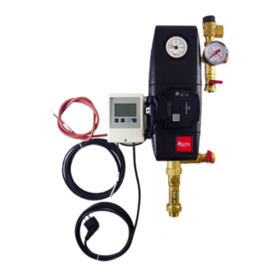
- Page 4 4. Pump Station Components 1 - SRS1 T CONTROLLER 2 - CIRCULATION PUMP 3 - CHECK VALVE 4 - BALL VALVE WITH SIDE OUTLET FOR SAFETY GROUP 5 - THERMOMETER (IN THE UPPER PART OF INSULATION) 6 - PRESSURE GAUGE 7 - EXPANSION VESSEL CONNECTION POINT, 3/4“...
-
Page 5: Installation Options
The ball valve is equipped with a spindle packing with two O-rings with dimensions of 8.7x1.8 mm that can be easily replaced by removing the control element with stop ends and loosening the pac- king nut with a # 21 spanner. WARNING! IMPORTANT! The safety relief valve, expansion vessel and upper filling/draining ball valve always remain connected with the solar thermal system, even when the ball valves are shut off! Never try to... - Page 6 6. Pump Station Connection Diagram 6.1 Variant with el. heating element 1 – hot water storage tank 2 – electric heating element with thermostat 3 – solar collectors 4 – CSE1 SOL SRS1 T solar pump station 5 – pump station for DHW recirculation –...
- Page 7 6.3 Overview of connection diagrams Explanation: light grey diagram number (6) - setup isn’t recommended for this pump station variant.
-
Page 8: Pump Control
7. UPM3 HYBRID 25-70 Pump Pump Control The circulation pump can be controlled: • internally without PWM signal by selecting a constant pressure or constant speed mode and a desired pump curve. • by an external PWM C control signal (profile for use in solar thermal systems) WARNING –... - Page 9 Description of Pump Frofiles a) INTERNAL CONTROL - Proportional pressure • Head (pressure): reduced with growing system pressure drop and increased with sinking system pressure drop. • Pump operating point: moves up or down on the selected proportional pressure curve depending on the current system pressure drop.
-
Page 10: Settings Display
Settings Display DISPLAY - LED MARKING The LED marking is further omitted for better clarity. DISPLAY CONTROL MODE green LED NOT FLASHING INTERNAL Proportional pressure AUTO - not used for ADAPT solar thermal systems Constant pressure AUTO - not used for solar ADAPT thermal systems Proportional pressure - not used... -
Page 11: Setting Selection
GREEN LEDS FLASHING CONTROL PWM SIGNAL RECEPTION FREQUENCY Not flashing Internal 1 flash per second External 12 flashes per second External WARNING: LEDs may be turned by 90° or 180°, or mirrored, depending on the specific pump type. When switched on, the pump runs at factory settings or the last setting. The display shows the current pump performance. - Page 12 ©2024 We reserve the right to errors, changes and improvements without prior notice. REGULUS spol. s r.o. E-mail: sales@regulus.eu Web: www.regulus.eu...
Need help?
Do you have a question about the CSE1 SOL G SRS1 T-P and is the answer not in the manual?
Questions and answers