
Related Manuals for Regulus CSE1 SOL W SRS1 T-K


Summary of Contents for Regulus CSE1 SOL W SRS1 T-K
- Page 1 Installation and Operation Manual CSE1 SOL W SRS1 T-K SOLAR PUMP STATION CSE1 SOL W SRS1 T-K...
- Page 2 G 3/4“ M G 1“ M Code 20571 20567 3. Pump Station Data Data for CSE1 SOL W SRS1 T-K Pump Station Max. fluid working temperature 110 °C Max. working pressure 6 bar Min. system pressure 1.3 bar with the pump stopped Flow rate measurement range 2–20 l/min...
- Page 3 Min. values of working pressure** Values of min. working pressure 0.8 bar at 50 °C at the pump suction port depending 1.2 bar at 90 °C on temperature 1.8 bar at 110 °C ** this condition is met for current installations when the initial system pressure is set following the formula (see the Instructions for solar collectors): p = 1,3 + 0,1·h [bar], where h ...
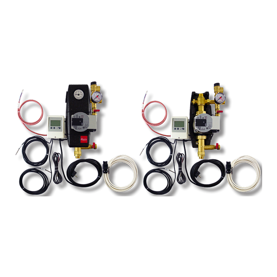
- Page 4 4. Pump Station Components 1 - SRS1 T CONTROLLER 2 - CIRCULATION PUMP 3 - CHECK VALVE 4 - BALL VALVE WITH SIDE OUTLET FOR SAFETY GROUP 5 - THERMOMETER (IN THE UPPER PART OF INSULATION) 6 - PRESSURE GAUGE 7 - EXPANSION VESSEL CONNECTION POINT, 3/4“...
-
Page 5: Installation Options
The ball valve is equipped with a spindle packing with two O-rings with dimensions of 8.7x1.8 mm that can be easily replaced by removing the control element with stop ends and loosening the pac- king nut with a # 21 spanner. WARNING! IMPORTANT! The safety relief valve, expansion vessel and upper filling/draining ball valve always remain connected with the solar thermal system, even when the ball valves are shut off! Never try to... - Page 6 6. Pump Station Connection Diagram 6.1 Variant with boiler (el./gas... fired)
- Page 7 6.2 Overview of connection diagrams Explanation: light grey diagram number (1, 3, 5, 6) - setup isn’t recommended for this pump station variant.
-
Page 8: Performance Curves
7. Wilo-Para iPWM2 Pump The Wilo Para 25/7 iPWM2 is a wet running circulation pump. The pump speed is controlled by the PWM signal. When the PWM signal is disconnected, the pump stops running (a pump profile for solar thermal systems). The operating status and possible faults of the pump are indicated by LEDs directly on the pump. - Page 9 7.3 Graphic signalling of pump operation The LED light signals a defect. The pump will switch off (depending on the defect type) and try to restart. LED Signals State Description and Possible Fault Reasons GREEN IS LIT 1 - pump is running in trouble-free operation 1 - rotor is blocked RED IS LIT 2 - electric motor winding defect...
- Page 10 9. Solar Thermal System Air Venting • During operation of the filling pump, close the lower drain valve and increase the pressure to about 5 bar; • close the upper filling valve and turn off the filling pump, open the ball valve above the pump, do not disconnect the filling pump hoses! •...
- Page 12 ©2024 We reserve the right to errors, changes and improvements without prior notice. REGULUS spol. s r.o. E-mail: sales@regulus.eu Web: www.regulus.eu...
Need help?
Do you have a question about the CSE1 SOL W SRS1 T-K and is the answer not in the manual?
Questions and answers