Regulus CSE2 MIX F G60 1F Installation And Operation Manual
Hide thumbs
Also See for CSE2 MIX F G60 1F:
- Installation and operation manual (24 pages) ,
- Installation and operation manual (16 pages) ,
- Installation and operation manual (16 pages)

Related Manuals for Regulus CSE2 MIX F G60 1F


Summary of Contents for Regulus CSE2 MIX F G60 1F
- Page 1 Installation and Operation Manual CSE2 MIX F G60 1F PUMP STATION CSE2 MIX F G60 1F...
-
Page 2: Table Of Contents
3.4. FILTER WITH MAGNET ..............3.5. BALL VALVES ................EXAMPLES OF PUMP STATION CONNECTION ........PUMP STATION INSTALLATION ............. TEMPERATURE SENSOR INSTALLATION ..........OPTIONAL ACCESSORIES ..............APPENDIX – ACTUATOR ADJUSTMENT ..........Regulus CSE2 MIX F G60 1F - www.regulus.eu │... -
Page 3: Introduction
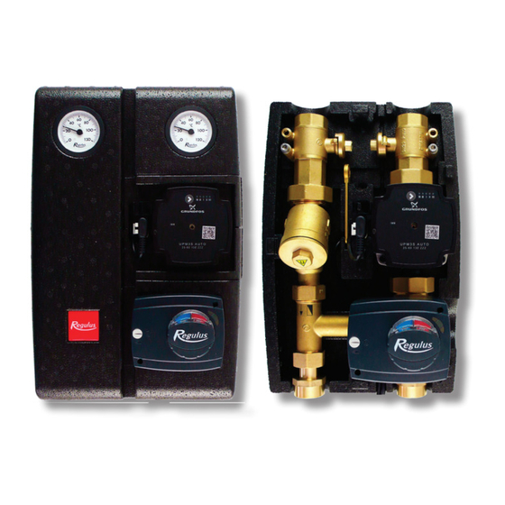
INTRODUCTION CSE2 MIX F G60 1F twin-line pump station is designed for mixed heating circuits. It provides flow through the heating system, mixes to the outlet temperature using a motorized mixing valve (controlled by an external controller). The pump station includes a filter with magnet, so it is also suitable for older steel pipe systems. -
Page 4: Pump Station Components
6 – Filter w. magnet 7 – Lever for ball valves 8 – Ball valve w. sheath for temperature sensor (heating circuit return) 9 – Ball valve w. sheath for temperature sensor (heating circuit flow) Regulus CSE2 MIX F G60 1F - www.regulus.eu │... -
Page 5: Grundfos Upm3 Auto 25-60 Pump
Pump control The circulation pump can be controlled by selecting a suitable profile and performance curve. Performance curves Line type Profile Constant speed Proportional pressure Constant pressure Regulus CSE2 MIX F G60 1F - www.regulus.eu │... - Page 6 • Pump operating point: moves up or down on the selected curve depending on the current system pressure drop. CONTROL MODE Max. H (upper graph) Max. P (lower graph) 25 W Constant 33 W speed 39 W Regulus CSE2 MIX F G60 1F - www.regulus.eu │...
- Page 7 Pump profiles can be switched by pressing the integrated button. The pump profiles change in a closed loop in the order shown in the table. Error Display DISPLAY ERROR Seized pump Too low power supply voltage Electric fault Regulus CSE2 MIX F G60 1F - www.regulus.eu │...
-
Page 8: Mixing Valve With Actuator
The ball valve can be accesses only after the front section of the insulation is removed. As a result, unintentional closure of the system by an unauthorized person is not possible. Regulus CSE2 MIX F G60 1F - www.regulus.eu │... - Page 9 OPEN CLOSED groove in the flow direction groove perpendicular to the flow direction Regulus CSE2 MIX F G60 1F - www.regulus.eu │...
-
Page 10: Examples Of Pump Station Connection
EXAMPLES OF PUMP STATION CONNECTION Regulus CSE2 MIX F G60 1F - www.regulus.eu │... - Page 11 Regulus CSE2 MIX F G60 1F - www.regulus.eu │...
-
Page 12: Pump Station Installation
Permitted and prohibited positions of the pump station Permitted position Conditionally permissible positions Prohibited position (may be used when a filter is replaced by the filter replacement section, code 19017) Regulus CSE2 MIX F G60 1F - www.regulus.eu │... -
Page 13: Temperature Sensor Installation
Temperature sensor placement Securing the temperature sensor with the screw Running the sensor cable through the recess in the insulation Regulus CSE2 MIX F G60 1F - www.regulus.eu │... - Page 14 Trimming the cable passage lock Installed sensors Regulus CSE2 MIX F G60 1F - www.regulus.eu │...
-
Page 15: Optional Accessories
A – Filter replacement section for CSE2 Code 19017 Loosen the unions above and under Remove the filter and mount the filter the filter. replacement section (code 19017) in its place. Regulus CSE2 MIX F G60 1F - www.regulus.eu │... - Page 16 Union 1“ Fu/M incl. gasket Code 15695 Remove both the connecting fittings. Install the union 15695 in their place, then attach the ball valve w. drain valve (17415) to the union. Regulus CSE2 MIX F G60 1F - www.regulus.eu │...
- Page 17 (for flow line of CSE2 pump stations) Code 18797 Remove both the connecting fittings. Install the extended union with check valve (18653) to the return line. Install the extended union (18797) to the flow line. Regulus CSE2 MIX F G60 1F - www.regulus.eu │...
- Page 18 D – Union to connect CSE2 to 5/4” manifold - 1“x5/4“ Fu/F Code 17920 Remove both the connecting fittings. Replace them with the union 17920 intended for connection to a manifold. Regulus CSE2 MIX F G60 1F - www.regulus.eu │...
-
Page 19: Appendix - Actuator Adjustment
Fit the plastic adapter on the shaft. The flat edge of the shaft and the arrow on the plastic adapter are located on the same side as the valve member. arrow on plastic adapter Regulus CSE2 MIX F G60 1F - www.regulus.eu │... - Page 20 The actuator shall be installed in the same manner as in the figure. v1.1-05/2022 ©2022 We reserve the right to errors, changes and improvements without prior notice. REGULUS spol. s r.o. E-mail: sales@regulus.eu Web: www.regulus.eu...
Need help?
Do you have a question about the CSE2 MIX F G60 1F and is the answer not in the manual?
Questions and answers