Regulus CSE2 SOL W SRS3 E P Installation And Operation Manual
Solar pump station
Hide thumbs
Also See for CSE2 SOL W SRS3 E P:
- Installation and operation manual (10 pages) ,
- Installation and operation manual (10 pages)

Related Manuals for Regulus CSE2 SOL W SRS3 E P


Summary of Contents for Regulus CSE2 SOL W SRS3 E P
- Page 1 Installation and Operation Manual CSE2 SOL W SRS3 E P SOLAR PUMP STATION CSE2 SOL W SRS3 E P...
- Page 2 2-12 l/min 20373 20452 20457 Code 3. Pump Station Data Data for CSE2 SOL W SRS3 E P Pump Station Max. fluid working temperature 110 °C Max. working pressure 6 bar Min. system pressure 1.3 bar with the pump stopped...
- Page 3 Min. values of working pressure** Values of min. working pressure 0,8 bar at 50 °C at the pump suction port depending 1,2 bar at 90 °C on temperature 1,8 bar at 110 °C ** this condition is met for current installations when the initial system pressure is set following the formula (see the Instructions for solar collectors): p = 1,3 + 0,1·h [bar], where h…...
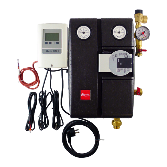
- Page 4 4. Pump Station Components 1 - FLOWRATE INDICATOR WITH BALLVALVE 2 - SOLAR CIRCULATION PUMP 3 - CHECK VALVE 4 - BALL VALVE ON THE INLET PIPE FROM THE SOLAR COLLECTORS 5 - BALL VALVE WITH SIDE OUTLET FOR SAFETY GROUP 6 - THERMOMETERS (IN THE UPPER PART OF INSULATION) 7 - PRESSURE GAUGE...
-
Page 5: Installation Options
The upper ball valves are operated by a lever which is not located on the valve during operation. Turning the lever or the key or pliers a quarter turn to the right closes the ball valve. It opens when the lever is turned to the left. Before closing / opening the ball valve, it is necessary to remove the top part of the insulation. - Page 6 7. Pump Station Connection Diagram with two solar consumers - diagram 17 1 – hot water storage tank 2 – electric heating element with thermostat 3 – solar collectors 4 – CSE2 SOL SRS3 solar pump station 5 – VZU R (VZK R) zone ball valve w. actuator 6 –...
- Page 7 R1(V1) R1(V1) Universal Delta T Shut-off valve Solar thermal system with pool and heat exchanger R1(V1) R1(V1) R1(V1) Solar thermal system with thermostat (heating) Solar thermal system with layered storage tank Solar thermal system with heating circuit R1(V1) R1(V1) R1(V1) 2 solar collector arrays I/O and 3-way valve Solar thermal system with heat exchanger Solar thermal system with bypass...
- Page 8 ❄ R1(V1) R1(V1) R1(V1) Solar thermal system with cooling 1 Solar thermal system with cooling 2 Solar thermal system with hot water (collector cooling) (collector cooling) storage tank and solid fuel boiler R1(V1) R1(V1) R1(V1) Solar thermal system with cooling 3 (collec- Solar thermal system with hot water storage tank 2 solar arrays E/W and solid fuel boiler and S4...
-
Page 9: Performance Curves
8. Wilo-Para iPWM2 Pump The Wilo Para 25/7 iPWM2 is a wet running circulation pump. The pump speed is controlled by the PWM signal. When the PWM signal is disconnected, the pump stops running (a pump for solar thermal systems). The operating status and possible faults of the pump are indicated by LEDs directly on the pump. -
Page 10: Technical Data
8.2 Technical Data Wilo PARA 25/7 iPWM2 Electric Data Power supply 1 ~ 230 V, 50 Hz Power input (min./max.) 1.8 / 50 W Current (min./max.) 0.02 / 0.43 A Max. speed 4700 rpm Energy Efficiency Index ≤ 0.20 by EN 16 297/3 IP rating IPX4D Motor protection... - Page 11 9. Filling a Solar Thermal System For filling a solar thermal system, the ball valve above the pump must be closed and the ball valves below the pump and on inlet pipe from the solar collectors open. The ball valves above the pump are operated by means of the enclosed spanner.
- Page 12 ©2024 We reserve the right to errors, changes and improvements without prior notice. REGULUS spol. s r.o. E-mail: sales@regulus.eu Web: www.regulus.eu...
Need help?
Do you have a question about the CSE2 SOL W SRS3 E P and is the answer not in the manual?
Questions and answers